
How to Use the FXTUL Sonic Belt Tension Tester

The FXTUL Sonic Belt Tension Tester is an acoustic belt tension tester. This guide combines the exact tester controls, acoustic measurement method and belt-data functions with a stationary-drive measurement and verification workflow.
Quick answer: Identify the exact belt, free span and new- or used-belt target first. Stop and isolate the drive, inspect the belt and pulleys, then enter the approved mass, width and span data. Aim the acoustic probe consistently at the stationary span, pluck the same point and keep only a repeatable set of readings. Adjust only by the equipment maker's engine-off procedure, then remeasure and restore every guard.
In this guide
Before you start
A belt drive can start unexpectedly and can pull fingers, clothing or tools into severe pinch points. Shut the engine or machine down, control the start key and apply the required lockout before a guard is removed or a belt is touched. The tester calculates from acoustic vibration plus the entered belt data; it cannot identify the belt, choose a universal target or make a damaged drive safe.
- obtain the exact belt identity, required mass or density and width data, defined free span and correct new- or used-belt acceptance range;
- stop, isolate and cool the drive so it cannot crank or start unexpectedly;
- inspect the belt, pulleys, bearings, tensioner and alignment before measuring;
- inspect the tester, acoustic probe, socket and four AAA batteries, then connect the probe with power off;
- control nearby fans, tools and vibrating panels that could contaminate an acoustic reading; and
- prepare the correct tensioner, torque and guard-restoration procedure before any adjustment.
Keep the manual supplied with the Sonic Belt Tension Tester beside the exact belt-drive service information and approved belt-data source. The physical unit labels, delivered instructions and drive maker’s procedure control if an older web image or retained record differs.
Sonic Belt Tension Tester controls and specifications
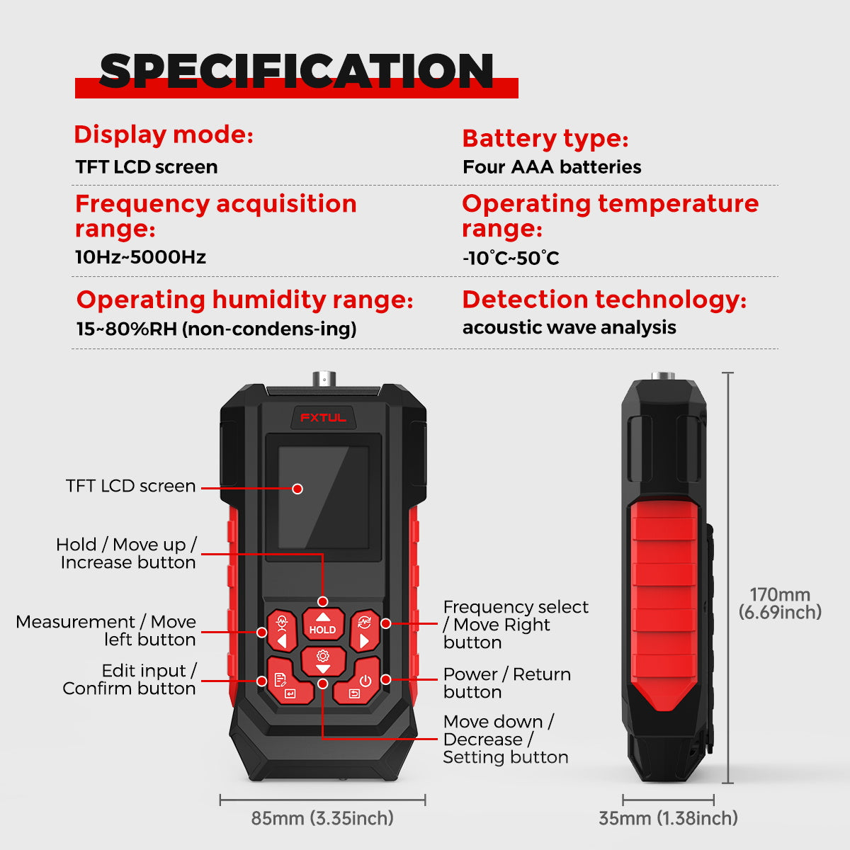
The current product record highlights Acoustic belt analysis, Single and continuous measurement, Belt-data selection, Custom data storage, Spectrum and TFT display. Confirm each relevant control on the physical unit before use; related FXTUL models can look similar while using different ranges, air sources or operating modes.
| Specification or function | Current model |
|---|---|
| Operating Temperature | -10°C to 50°C |
| Display | TFT color LCD |
| Frequency Measurement Range | 10-5000Hz |
| Battery | Four AAA batteries |
| Operating Mode | Single or continuous measurement |
| Relative Humidity | 15-80% RH, non-condensing |
The current product record identifies acoustic analysis, a 10-5000Hz acquisition range, single or continuous measurement, adjustable trigger intensity and storage for as many as 999 user-defined data sets. Those are instrument capabilities, not belt limits or target values. The actual boundary is the exact drive maker’s approved belt data, span definition, temperature or settling condition and acceptance range.
How to use the Sonic Belt Tension Tester
Step 1: Identify the exact belt and its tension specification
Use the machine, vehicle or belt maker's exact procedure to identify the belt, the specified free span, required belt mass or density and width data, acceptable tension or frequency, measurement condition and whether the limit is for a new or used belt. Do not borrow a target from a similar engine or belt.
Before moving on, confirm the exact belt record, defined span and matching target are open, and prove the stopped drive cannot crank or start while a guard is removed or the belt is touched.
Step 2: Stop, isolate and cool the belt drive
Switch the engine or machine off, remove or control the start key and apply the required lockout so no one can crank or start it. Wait for hot parts to cool, secure loose clothing and remove only the guard authorized by the service procedure. Never measure or adjust a moving belt.
Step 3: Inspect the belt, pulleys and free span
Check the belt for cracks, glazing, fraying, contamination, missing ribs or teeth and inspect pulleys, bearings, tensioners and alignment. Mark the exact unsupported span named by the procedure. A tension reading cannot make a damaged or misaligned drive serviceable.
Step 4: Inspect and prepare the tester and acoustic probe
Inspect the FXTUL tester, sensor socket, flexible probe, Type-C data port and four AAA batteries. Connect the exact probe with power off, switch the tester on and confirm the display and battery indicator are normal. Keep the sensor clean, dry and free from contact damage.
Step 5: Confirm the belt parameters and free-span length
Obtain the exact belt mass value, width and free-span length from controlled service information or an approved belt record. Measure the span by the method required for that drive. The values must describe the actual belt and selected span; guessed parameters can produce a stable but wrong tension calculation.

Step 6: Select or enter the exact belt data
Choose the matching built-in record or create a user-defined record, then verify mass, width and span on the parameter-input screen before measurement. Confirm units and decimal positions. If DATA.CSV is edited on a computer, back it up first, preserve the template and never disconnect USB while saving.
Step 7: Position the sensor and control background noise
Aim the acoustic probe at the selected free span using the position and distance specified by the delivered instructions, without touching the belt or nearby parts. Keep the probe orientation and distance consistent, silence fans and tools and prevent another belt or panel from vibrating into the reading.
Step 8: Pluck the belt and collect repeatable readings
Deflect and release the selected span in the approved direction so it vibrates freely, then trigger a single reading or use continuous mode as intended. Keep hands clear of pinch points and do not strike the probe. Repeat at least three times with the same pluck point and sensor position; reject a lone unstable value.
Step 9: Compare the stable result and adjust only while isolated
Compare the repeatable reading set with the exact new- or used-belt acceptance range and recorded measurement condition. If adjustment is required, switch the tester aside and follow the drive maker's tensioner and fastener procedure with the machine still isolated. Never adjust around a running belt and never force an automatic tensioner outside its service method.
Step 10: Remeasure, record and restore the drive
Where the service procedure permits, rotate the drive only by its approved manual method to settle the belt, return to the same defined span and remeasure. Record belt identity, parameters, span, readings, condition and final fastener checks. Refit every guard, remove lockout only through the site procedure and complete the specified controlled functional check.
Before restoring power, confirm the final repeatable reading set is recorded, every adjustment fastener is secure, the tester and probe are clear and all guards and lockout controls are restored by the site procedure.
Read and verify the result
Treat one displayed tension as provisional until the setup and repeatability are proven. A useful result ties together the belt identity, mass and width data, measured free span, sensor position, drive condition and a small set of closely grouped readings. Compare that set only with the matching new- or used-belt specification and investigate physical belt-drive faults even when the number appears acceptable.
- Repeat with the same span, sensor position and pluck point; a lone value is weaker evidence than a stable cluster.
- Recheck units, decimal positions, belt record and free-span measurement before changing tension for an unexpected result.
- Inspect contamination, pulley alignment, bearings and tensioner operation when readings drift or differ by drive position.
- Use only the drive maker’s engine-off adjustment and fastener-torque procedure; automatic tensioners may not permit manual correction.
- Record whether the belt was new, used, cold, settled or recently adjusted so a later comparison uses the same condition.
Stop for any possibility of unexpected start, a moving belt, an unsecured guard, a cracked or contaminated belt, damaged pulley or tensioner, hot or inaccessible work area, sensor contact with the belt, or readings that will not repeat after the setup is checked. Re-isolate the drive and correct the cause; do not keep plucking, adjust a running drive or tune tension to one unstable number.
Common mistakes and care
- Never measure, pluck or adjust a belt while the engine or machine is running or capable of unexpected start.
- Use the exact belt parameters, free span and new- or used-belt target from controlled service information; there is no universal correct tension.
- A stable reading can still be wrong when mass, width, span, units, sensor position or belt identity is wrong.
- Do not use a tension reading to approve a cracked, contaminated, frayed, misaligned or otherwise damaged belt drive.
- Control background noise and use the same pluck point, sensor position and drive condition for every comparison.
- Back up DATA.CSV before editing, preserve its exact format and never disconnect the USB connection while a file is being saved.
- Do not enter a similar belt’s mass, width or span because its name looks close; verify the actual controlled record.
- Do not measure one convenient span when the service procedure specifies a different span or drive position.
- Do not let the acoustic probe touch the belt or change its angle and distance between comparison readings.
- Do not accept an on-screen tension merely because it is stable when the units, record or span may be wrong.
- Do not edit DATA.CSV without a backup or interrupt the USB connection while saving the retained data table.
Frequently asked questions
Can I measure belt tension with the engine running?
No. Stop and isolate the drive so it cannot crank or start, then measure only the stationary free span. A rotating belt creates entanglement and pinch hazards and does not match this acoustic pluck workflow.
What mass, width and span values should I enter?
Use the values specified for the exact belt and defined free span by the equipment, vehicle or belt maker. Do not copy values from a similar belt or estimate them from appearance; wrong inputs can produce a stable but wrong calculated tension.
Why does the reading change every time I pluck the belt?
Check the selected record, free-span measurement, units, sensor position, background noise and whether you use the same pluck point and direction. Also inspect the belt, pulleys, alignment, bearings and tensioner. Adjust only after a repeatable setup is established.
Final Sonic Belt Tension Tester checklist
- Exact belt identity, approved parameters, defined span and matching target confirmed
- Drive stopped, cooled and isolated; unexpected start prevented
- Belt, pulleys, bearings, tensioner and alignment inspected
- Probe and tester intact; four AAA batteries and display normal
- Mass, width, span, units and stored record verified before measurement
- At least three readings repeat under the same pluck and sensor conditions
- Any adjustment completed only by the isolated drive procedure and torque requirements
- Final values recorded and every guard and control restored before functional check
Reliable acoustic belt measurement is a controlled comparison, not a one-button verdict: identify the belt, enter exact data, isolate the drive, repeat the same pluck and sensor geometry, then adjust and verify only by the equipment maker’s procedure.











Comments 0
Questions, fixes, and real-world diagnostic notes from readers.
Be the first to share a diagnostic result or ask a follow-up question.