
How to Use the MRCARTOOL Cooling System Vacuum Refill Kit

The MRCARTOOL cooling system vacuum refill kit uses workshop compressed air to create vacuum in a drained cooling system, check whether that vacuum remains stable and draw premixed coolant back through the inlet hose. The method can reduce trapped air, but only after the engine is cold and the vehicle’s drain, coolant, refill, bleed and final-level instructions are known.
Quick answer: With the engine completely cold, assemble the correct conical adapter, 1 m inlet hose, 0.5 m outlet hose and 1/4-inch shop-air coupler. Start with valve 1 open and valve 2 closed, seal the adapter squarely in the reservoir neck, connect regulated air within the tool’s 5.5–12 bar range and route the outlet hose to a container. When the gauge reaches more than −80 kPa or stops changing, close valve 1 and disconnect air. The needle must remain steady. If it falls, repair the leak and repeat. Submerge the inlet hose in enough new premixed coolant, open valve 2 slowly and let system vacuum draw coolant in. Close the valve before the supply uncovers, remove the tool and complete the vehicle-specific bleed and level check.
In this guide
Qualify the vehicle, coolant and work area
1. Let the cooling system become completely cold
Never remove a radiator or expansion-tank cap from a hot or pressurized system. Park the vehicle on the surface and in the attitude required by its service information, switch the engine off and wait until the cooling system is safe to open. Wear eye protection and coolant-resistant gloves. Keep coolant away from children and animals; collect every discharge in a closable container.
2. Read the vehicle procedure before draining
Identify whether the kit connects at a radiator neck, pressurized expansion tank or another specified fill point. Confirm the correct coolant specification, concentration, total system capacity, drain points, heater-control requirements and final bleed sequence. Vacuum filling is not permission to skip drain plugs, bleed screws, electric-pump routines or scan-tool functions required by the vehicle.
Keep the exact MRCARTOOL coolant exchange kit manual available for the tool sequence. It specifies 5.5–12.0 bar working air pressure, maximum air use of 100 L/min at 6 bar, a 1/4-inch female air connection and a tool working-temperature range of −20 to +50°C. Those are tool limits, not permission to connect to a hot engine.
3. Prepare enough correct premixed coolant
Stage more new premixed coolant than the estimated refill volume in a clean, stable container. The inlet hose must remain submerged throughout filling; if it draws air, the purpose of vacuum filling is defeated. Do not mix coolant chemistries because the colors look similar. If concentrate must be used, prepare the approved concentration with specified water before the inlet hose enters the container.
Do not create vacuum in a cooling system that is visibly damaged or not approved for vacuum filling. Inspect hoses, radiator, reservoir, caps and repaired joints first. Vacuum can reveal leakage, but it does not certify every pressure-related fault or replace the vehicle’s specified pressure test.
Assemble the MRCARTOOL kit
4. Inspect and identify all parts
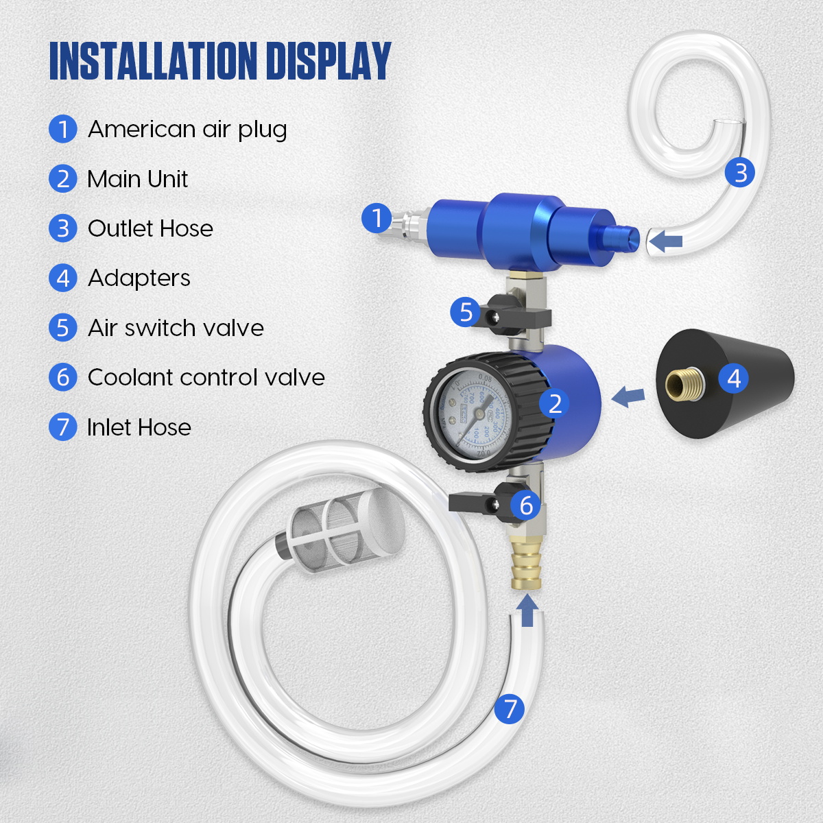
Confirm the main unit, gauge, valve 1, valve 2, male shop-air coupler, three conical adapters, 1 m inlet hose and 0.5 m outlet hose are present. The manual lists adapter ranges of 16–33 mm, 23–41 mm and 34–52 mm. Check the gauge lens and pointer, valves, threads, hose ends and adapter rubber for cracks, cuts, contamination or looseness. Replace damaged parts rather than improvising a seal.
5. Install the air coupler and hoses in their labeled positions
Fit the male coupler to the shop-air port using the approved sealing method for that fitting. Connect the inlet hose to the port shown in the manual and video, and connect the shorter outlet hose to its separate port. A reversed hose arrangement can discharge residual coolant into the new supply, so compare the assembled unit with the manual diagram before continuing.
6. Select and fit the conical adapter
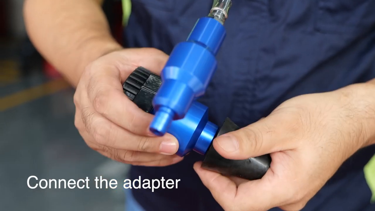
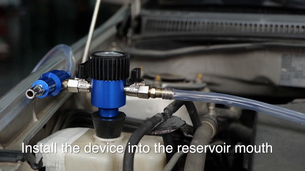
Choose the smallest adapter whose taper seats securely across the reservoir opening without dropping through or being wedged beyond its working range. Mount it at the tool position shown in the manual. Keep sealing surfaces clean. The adapter must sit square and the main unit must be held straight; side load can admit air and make a sound cooling system appear to leak.
7. Route the outlet and inlet hoses safely
Place the outlet hose in a compatible waste container because the manual warns that remaining coolant may be pushed out while vacuum is generated. Keep the inlet hose clean and out of the new coolant for now. Route both hoses away from belts, fans, exhaust parts and sharp edges. Secure the shop-air hose so it cannot pull the main unit sideways.
Pull and hold vacuum
8. Set the two valves for evacuation
Before connecting air, open valve 1 and close valve 2, exactly as the official manual instructs. Verify the outlet hose remains in the waste container. Regulate workshop air within 5.5–12.0 bar and confirm the air system can support the stated demand without uncontrolled pressure fluctuation. Do not exceed the tool rating or feed oxygen or another gas.
9. Connect shop air and watch the gauge
Connect the air source while keeping the unit upright and the adapter sealed. The venturi section draws air from the cooling system and the gauge moves into vacuum. Watch the outlet hose for expelled residual coolant and keep the container stable. Do not leave the tool unattended, and stop if the adapter lifts, a hose whips or coolant sprays.
10. Reach the manual’s target, then isolate the system
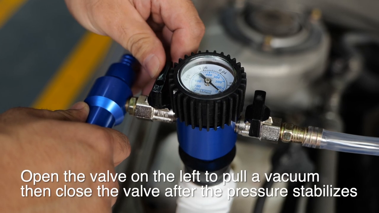
Continue only until the gauge reaches more than −80 kPa or the reading becomes stable, as stated by the manual. Close valve 1 first, then disconnect shop air. Closing the valve before removing air isolates the cooling system from the venturi path. Do not chase a deeper reading beyond the documented target or exceed the vehicle’s allowed vacuum.
11. Perform the vacuum-hold check
Observe the gauge with both flow paths isolated. A steady reading indicates that the system and adapter seal are holding vacuum for this step. If the needle moves back toward zero, check the conical adapter and tool connections before condemning the vehicle. If the tool seal is sound, locate and repair the cooling-system leak, then repeat evacuation from the beginning. Do not refill under a falling vacuum and assume the leak has disappeared.
Vacuum-fill with new coolant
12. Submerge the inlet hose before opening valve 2
Place the clean inlet hose at the bottom of the prepared coolant container. Keep its end fully submerged and arrange the container so it cannot tip. The hose should not curl above the liquid during the draw. Confirm shop air is disconnected, valve 1 is closed and the vacuum reading is stable before changing to refill mode.
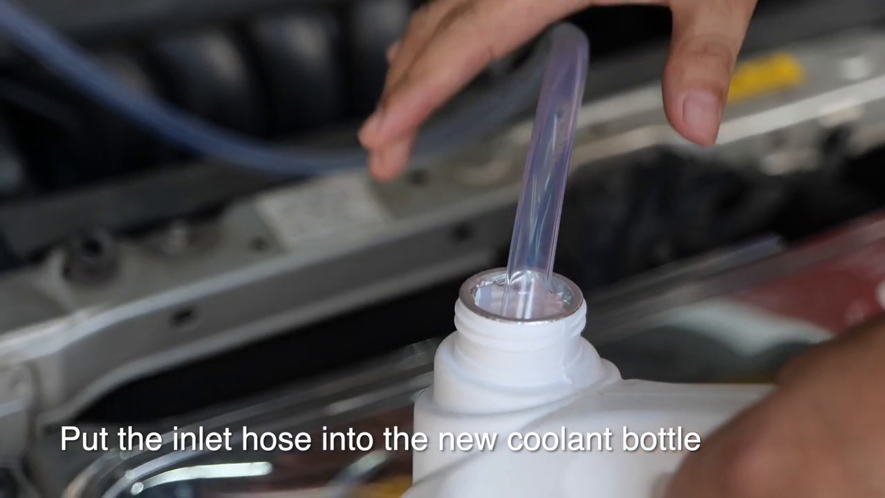
13. Open valve 2 slowly
Open valve 2 gradually. System vacuum now draws coolant through the inlet hose. Watch for a continuous liquid column and monitor the coolant container, hose and gauge together. Slow valve movement helps prevent the hose from jumping and gives time to stop before the supply uncovers. Do not add shop-air pressure during this stage; vacuum in the vehicle is doing the filling.
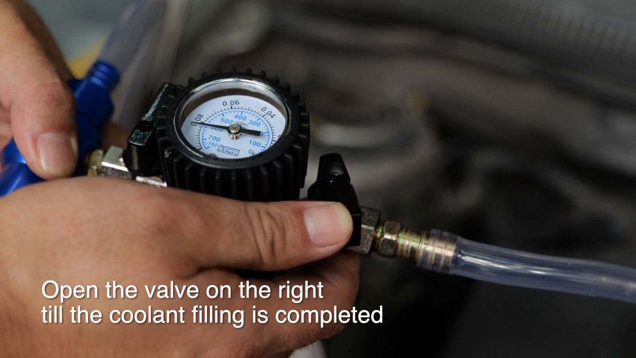
14. Stop cleanly when filling is complete
As vacuum decays and coolant flow slows, keep the inlet submerged. Before removing it from the coolant, close valve 2 so air cannot enter the system through the hose. Record the approximate amount drawn and compare it with the expected refill volume. A large unexplained shortfall may indicate trapped coolant, an incomplete drain, a closed circuit or an incorrect service path; investigate rather than forcing more fluid.
Finish the vehicle procedure
15. Remove the tool under drip control
With both valves closed and shop air disconnected, release any remaining condition only as the manual and vehicle procedure allow. Hold the main unit straight, remove it from the reservoir and cap or reinstall the specified pressure cap. Wipe spills promptly. Inspect the adapter and reservoir neck to make sure no rubber fragment or debris remains.
16. Run the required bleed and level checks
Follow the vehicle-specific finishing sequence. That may include opening bleed screws, commanding an electric water pump, setting the heater, running the engine through a defined cycle, allowing a complete cool-down and checking level again. Never rely only on the amount drawn from the bucket. Watch temperature data and heater output, and stop the engine if temperature rises abnormally or coolant circulation is uncertain.
Reinspect the reservoir, cap, hose joints, drain plugs and recently serviced areas for leakage. Confirm the final cold level after the vehicle reaches the condition specified by its manufacturer. A successful vacuum draw does not prove the pressure cap, combustion sealing or every hot-operating condition is fault-free.
17. Clean and store the kit
Drain the inlet and outlet hoses into the correct coolant waste stream. Rinse only by a method compatible with the coolant and tool materials, then dry as instructed. Do not discharge coolant to the ground or drain. Inspect the gauge and valve operation, coil hoses without kinks, keep adapters together and store the unit within its stated environmental range, protected from impact and contamination.
Troubleshooting
| Symptom | Check first |
|---|---|
| Gauge does not move into vacuum | Valve 1 open, valve 2 closed, air supply within rating, correct port connections and adapter sealed |
| Vacuum stops below target | Airflow capacity, adapter side load, loose hose, open bleed point or cooling-system leak |
| Gauge falls after isolation | Close valve 1 fully; leak-check tool joints and adapter, then diagnose the vehicle if the tool seal is sound |
| Coolant exits the outlet hose | This can be residual system coolant during evacuation; keep the outlet in a compatible waste container |
| Coolant will not draw in | Stable vacuum present, shop air disconnected, valve 1 closed, valve 2 opening, inlet submerged and hose unkinked |
| Bubbles appear in the inlet hose | Coolant level too low, hose end uncovered, loose connection or cracked hose |
| Refill volume is much lower than expected | Incomplete drain, closed circuit, wrong connection point or vehicle-specific bleed step still required |
| Engine temperature rises after service | Stop; verify level, circulation, required bleed routine, leaks and correct coolant before further operation |
Final coolant vacuum-fill checklist
- Engine and cooling system completely cold
- Exact vehicle drain, coolant, refill and bleed procedure available
- Enough correct premixed coolant staged in a clean container
- Main unit, gauge, valves, hoses and three adapters inspected
- Correct adapter selected within its published size range
- Inlet and outlet hoses connected to their correct ports
- Outlet hose secured in a compatible waste container
- Tool held straight with an even reservoir seal
- Regulated shop air within 5.5–12.0 bar
- Evacuation started with valve 1 open and valve 2 closed
- Vacuum reached more than −80 kPa or stabilized
- Valve 1 closed before shop air was disconnected
- Gauge remained steady during the hold check
- Any leak corrected before refill
- Inlet hose kept submerged in new coolant
- Valve 2 opened slowly and closed before supply uncovered
- Tool removed with both valves closed and air disconnected
- Vehicle-specific bleed and final cold-level checks completed
- No leak, abnormal temperature or uncertain circulation remains
- Coolant waste contained and kit cleaned and stored
The safest sequence is simple and strict: work cold, assemble the correct hose path, seal the adapter squarely, evacuate with valve 1, isolate and prove the vacuum holds, then draw premixed coolant through valve 2. Finish with the vehicle’s own bleed and level routine. The gauge confirms the tool’s vacuum stage; the vehicle procedure confirms the cooling system is actually ready for service.











Comments 0
Questions, fixes, and real-world diagnostic notes from readers.
Be the first to share a diagnostic result or ask a follow-up question.