
How to Use the AUTOOL CT500 GDI Fuel Injector Cleaner and Tester

Use the AUTOOL CT500 only after identifying each injector, its exact adapter, its fixed drive voltage, and its permitted test pressure and pulse data. Preserve cylinder identity, clean compatible working ends in the unheated ultrasonic bath, prove the external fixture dry, then compare leakage, spray, and delivered volume under one recorded condition. A trustworthy result is repeatable and follows the injector through a position swap.
The CT500 can clean and compare as many as six compatible gasoline injectors. It offers fixed 12 V, 70 V, and 120 V drive selections, a 28 kHz ultrasonic bath, a 0–40.0 ms PWM control range, and a 0–0.8 MPa system-pressure range. These are machine capabilities, not universal settings. The CT500 does not heat its ultrasonic bath, and exact injector data plus the lowest applicable machine, injector, fluid, and service limit always control.
In this guide
- What the CT500 can—and cannot—tell you
- Before you start
- Understand the machine before adding liquid
- Build one traceable setup sheet
- CT500 step-by-step operating procedure
- How to interpret the result without overdiagnosing
- When to use pulse, wide-pulse, and continuous modes
- When reverse flushing is appropriate
- Common CT500 mistakes
- CT500 operating checklist
- Frequently asked questions
What the CT500 can—and cannot—tell you
The AUTOOL CT500 combines an ultrasonic bath, six measuring cylinders, a pressurized test-fluid circuit, pulse controls, and three fixed drive-voltage choices. With a controlled setup, it can help you compare:
- nozzle leakage after every external joint is proven dry;
- spray shape, direction, atomization, and shutoff;
- delivered volume at the same voltage, pressure, pulse, fluid, time or count, and drain state;
- response in idle, medium-speed, high-speed, accelerating, variable-speed, pulse, wide-pulse, and continuous modes when injector data permits them;
- the same injector set before and after a controlled cleaning cycle.
The 15 menu items are selectable cleaning and test functions, not a sequence that every injector must complete. The diagnostic core is usually ultrasonic cleaning, a fixture-proven leakage check, a matched spray comparison, a matched volume comparison, and a repeat of the original baseline. Advanced pulse and reverse-flush modes are conditional.
The CT500 does not reproduce the high-pressure side of a running gasoline direct-injection engine. Its GDI, EFI, and FSI support means compatible injectors can be mounted and driven with the correct adapter and fixed voltage for comparative bench work within the machine’s range. A 0–0.8 MPa bench cannot prove operation at engine rail pressure, combustion temperature, or the vehicle controller’s complete waveform.
It also cannot replace injector-specific specifications. If the part number, drive requirement, adapter, pressure, pulse limit, material compatibility, or acceptance limit is unknown, stop and obtain that information before energizing or pressurizing the injector.
Before you start
Download the instructions for the delivered machine revision from the AUTOOL manual download center. Confirm the CT500 nameplate voltage matches a grounded outlet and that its power cord, fuse, hoses, adapters, seals, glass cylinders, valves, gauge, and guards are undamaged.
Prepare:
- current vehicle-maker instructions for relieving fuel pressure, removing and reinstalling injectors, renewing seals, torquing the rail, and checking the vehicle for leaks;
- the injector part number, electrical drive voltage, service pressure, pulse data, material limits, and pass/fail criteria;
- the correct CT500 adapters, plugs, signal leads, serviceable O-rings, and specified O-ring lubricant;
- approved ultrasonic injector-cleaning liquid and approved injector test fluid in separate labeled containers;
- safety glasses, fluid-resistant gloves, ventilation, absorbent material, and approved waste-fluid containers;
- a worksheet for original cylinder, machine channel, setup values, observations, repeat runs, and position swaps.
Place the machine level on all four feet in a dry, bright, ventilated work area between 0°C and 40°C. Keep flames, sparks, cigarettes, hot work, and unprotected electrical equipment away from injectors and service liquids. Do not use gasoline, kerosene, thinner, or an improvised reagent. Never run the ultrasonic tank dry, leave a powered test unattended, loosen a pressurized fitting, or put your face close to an operating injector.
Stop: Do not continue with a damaged cord, grounding connection, hose, adapter, O-ring, injector body, connector, glass cylinder, valve, gauge, or guard. Stop immediately for an external leak, unstable pressure, wet electrical connection, cracked glass, abnormal heat, odor, smoke, sound, vibration, or control response.
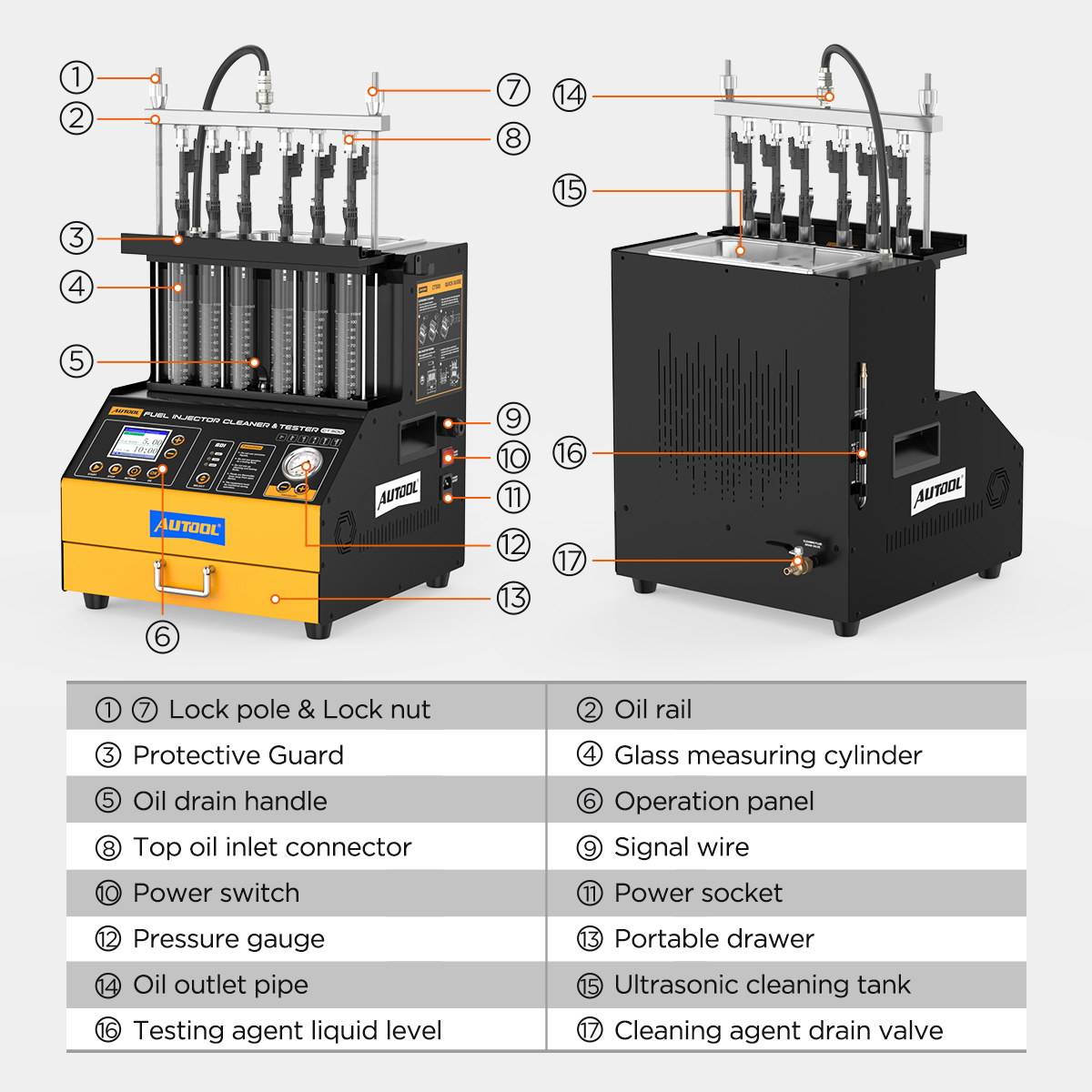
Understand the machine before adding liquid
The CT500 has two liquid circuits with different jobs. The ultrasonic tank holds cleaning liquid around compatible injector working ends. The internal reservoir, supply path, rail, and six measuring cylinders use dedicated test fluid for pressure, leakage, spray, and flow comparison. Never pour cleaning liquid into the test-fluid circuit or test fluid into the ultrasonic bath.
Locate the six glass measuring cylinders, protective front structure, control panel, pressure gauge, accessory drawer, lock rods, distributor rail, outlet pipe, ultrasonic tank, cleaning-liquid drain, test-fluid level indicator, test-fluid drain, signal wires, power inlet, and power switch on the delivered machine. Label placement may differ slightly by production revision, so follow the physical valve and flow path rather than relying only on memory.
The display and controls select a menu item, edit its allowed parameters, start or stop the function, choose one fixed injector voltage, and raise or lower test pressure. The menu contains ultrasonic cleaning; idle, medium-speed, high-speed, accelerating, and variable-speed tests; leakage; three spray-value modes; reverse flushing; no-disassembly cleaning; pulse injection; wide-pulse injection; and continuous injection.
No-disassembly cleaning interacts with the vehicle fuel system, combustion chamber, ventilation, and model-specific fittings. It requires its own vehicle procedure and is not part of this removed-injector bench guide.
Build one traceable setup sheet
Record the following before energizing an injector:
| Item | What to record | Why it matters |
|---|---|---|
| Identity | full part number and original vehicle cylinder | preserves diagnostic traceability |
| Fixture | lower position, upper adapter, seal, plug, and machine channel | separates injector faults from setup faults |
| Electrical | exact 12 V, 70 V, or 120 V requirement | prevents trial escalation, overheating, or damage |
| Hydraulic | injector test pressure within the 0–0.8 MPa machine ceiling | keeps the comparison relevant and within both limits |
| Pulse | menu mode, pulse width, time or count, and injector limit | makes repeat and before/after results comparable |
| Fluids | approved cleaning liquid and dedicated test fluid | protects pump, seals, coating, and result quality |
| Acceptance | allowed leakage, pattern, and volume tolerance | prevents a generic example becoming a diagnosis |
Use a matched injector set whenever possible. If fewer than six injectors are installed, close every unused distributor outlet with the correct CT500 plug. Never improvise a cap.
CT500 step-by-step operating procedure
Step 1: Relieve pressure, remove, identify, and label
Relieve vehicle fuel pressure exactly as the vehicle maker specifies. Disconnect the battery only when the service procedure requires it. Protect open fuel lines and intake ports as soon as the rail is removed.
Label every injector by original cylinder before mixing the set. Record the complete part number, connector type, visible condition, seal condition, and any symptom linked to that cylinder. This is what lets you reconcile the bench result with misfire counts, fuel trims, compression, wiring, and rail-pressure data later.
Completion check: Every injector has a durable identity, vehicle openings are protected, and the baseline worksheet is started.
Step 2: Inspect injectors, glass, and every pressure interface
Remove loose exterior dirt by an injector-approved method. Reject or route for specialist inspection any cracked body, damaged connector, bent tip, corroded terminal, scored sealing land, or unknown modification. Renew service seals when the injector or vehicle procedure requires it.
Inspect each selected adapter, O-ring, plug, rail port, hose, lock rod, and measuring cylinder. A scratched adapter or rolled O-ring can imitate injector leakage. A crooked upper adapter can side-load the injector. Quartz-glass cylinders can be damaged by impact or off-axis force, so keep tools and loose objects away from the front of the machine.
Common mistake: Calling fluid outside the injector a nozzle leak. The rail, adapter, plug, hose, and O-ring joints must remain dry before a nozzle observation is valid.
Step 3: Confirm adapter, voltage, pressure, and pulse limits
Match the full injector part number to its correct mechanical adapters, signal lead, fixed drive voltage, test pressure, pulse-width range, and acceptance limits. The CT500 offers 12 V, 70 V, and 120 V choices for different injector electrical designs. They are not a safe sequence to try from low to high.
Confirm that the intended pressure is inside both the injector requirement and the CT500’s 0–0.8 MPa machine ceiling. Its PWM control can display values from 0 to 40.0 ms in 0.1 ms steps, but that range does not make every value safe for every injector. Do not copy a pressure, pulse width, test time, injection count, or balance percentage from another injector.
Pass condition: A written setup sheet ties each injector to one verified adapter arrangement, fixed voltage, pressure, pulse limit, and acceptance method.
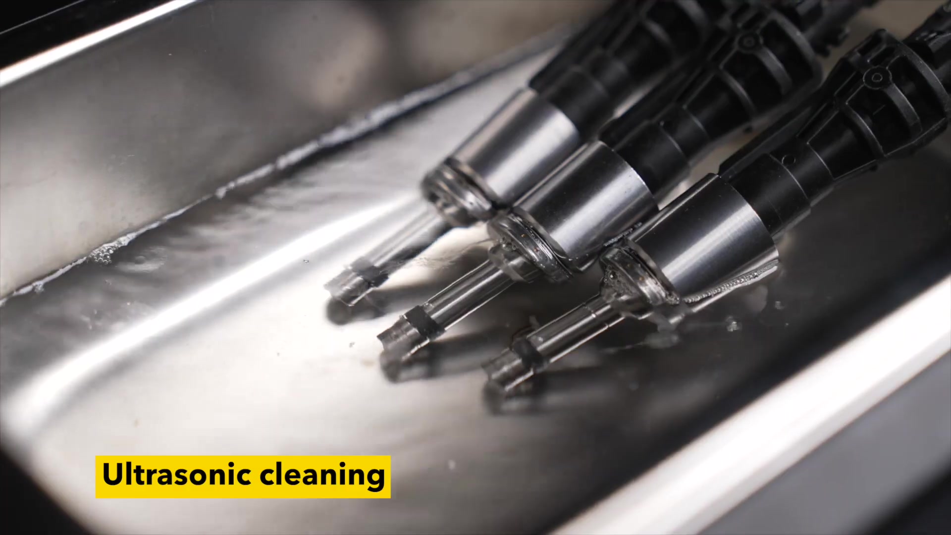
Step 4: Load and run the unheated ultrasonic bath
Place the cleaning stand in the ultrasonic tank, then add approved cleaning liquid to the delivered machine’s safe working level before selecting ultrasound. The liquid should cover only the intended cleaning area without submerging electrical connectors or lead junctions and without overflowing after all injectors are positioned.
Place compatible working ends in the stand and keep the connectors dry. The CT500 has no bath-heating function. Do not add an external heater, pour in hot liquid to imitate another model, or transfer a CT450 temperature procedure to this machine.
Select item 01, Ultrasonic Cleaning. Set only a duration permitted by the injector, liquid, and service procedure. Connect pulse leads during cleaning only when the exact injector data and procedure permit pulsing. Start the cycle and watch liquid level, injector position, electrical dryness, sound, and machine behavior throughout.
Stop: Stop at once if the tank approaches dry operation, liquid threatens a connector, an injector moves, liquid overflows, or the machine develops abnormal heat, odor, smoke, noise, vibration, or control behavior.
Completion check: Cleaning finishes without dry running, overflow, wet electrical connections, external heating, coating damage, or loss of injector identity.
Step 5: Finish the bath stage without mixing fluids
Press Stop before touching a lead or injector. Remove injectors without pulling their wires, let excess cleaning liquid drain into the bath, and wipe external surfaces with a compatible soft material. Keep the working ends and connectors protected from new contamination.
Recover, retain, or discard the cleaning liquid only as its label and local rules allow. Keep it out of the CT500 test-fluid reservoir. If it is contaminated beyond its service condition, place it in an approved labeled waste container.
Pass condition: Injectors are dry at electrical connections, still labeled, externally clean, and ready for clean adapter installation.
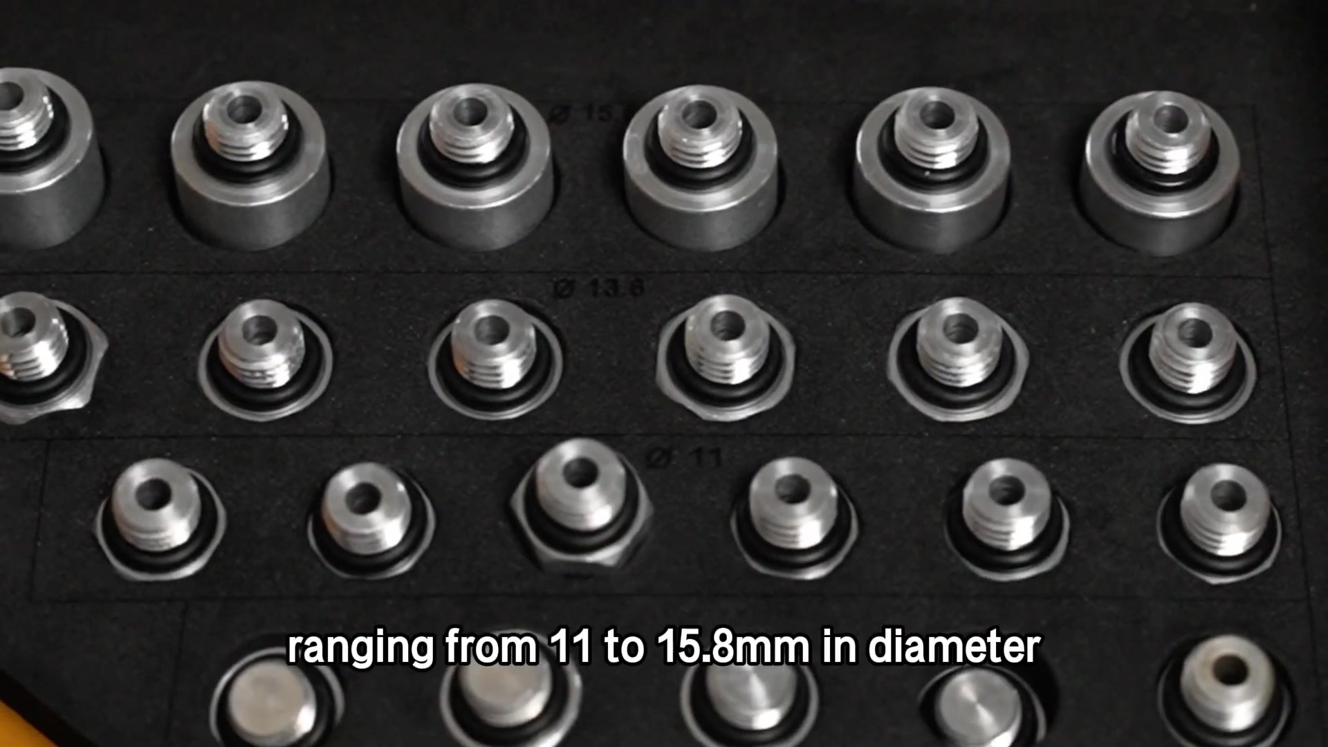
Step 6: Match the lower positions, upper adapters, and leads
Lay out the six machine channels in original-cylinder order. Select the exact lower position and upper adapter for the identified injector. Diameter is only one fit characteristic; the sealing land, depth, shoulder, inlet geometry, electrical connection, and supported injector family must also match.
Apply only the lubricant specified for the O-ring and only enough to avoid cutting or rolling it. Push straight and stop if force is needed. Confirm the seal is not twisted, shaved, or extruded. Install the exact signal lead and verify connector orientation without forcing terminals.
Completion check: Each injector seats squarely by hand with a serviceable seal, correct lead, and documented channel. No part was chosen merely because it looked close.
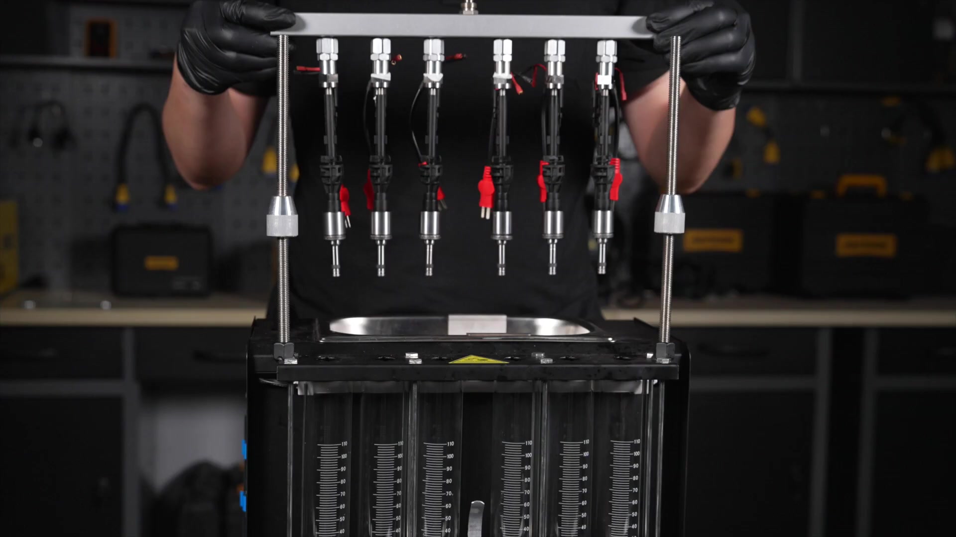
Step 7: Align and secure the six-injector rail
Place injectors vertically in their numbered lower positions. Align the distributor over all upper adapters before lowering it; never use the rail to pull a crooked injector into position. Start both lock rods by hand and tighten them alternately in small steps so the distributor remains level.
Connect the outlet pipe and close every unused rail outlet with its specified plug. Connect signal leads in channel order and route them away from liquid, sharp edges, moving hands, and anything that can pull an injector sideways.
Common mistake: Fully tightening one side first. A tilted distributor distorts seals, side-loads glass and injectors, and creates a fixture leak that can be mistaken for an injector fault.
Pass condition: The rail is level, injectors are vertical, outlets are closed, leads are strain-free, and every channel still matches the worksheet.
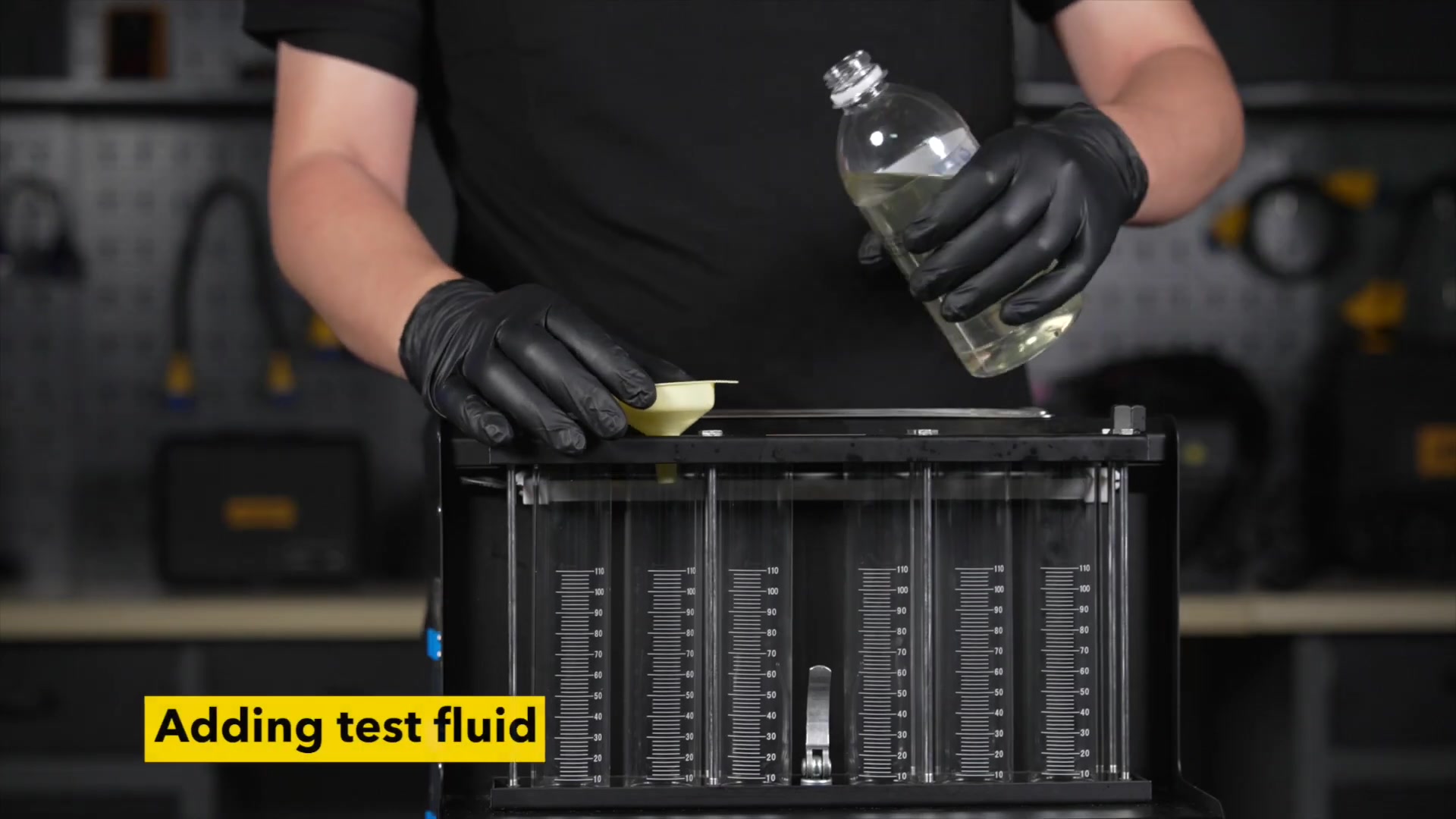
Step 8: Add dedicated test fluid and set the drain state
With the CT500 stopped and unpressurized, place its test-fluid controls in the fill position specified for the delivered machine. Add fresh approved injector test fluid through the designated path at a controlled rate, watching the level indicator and preventing overflow. Do not use ultrasonic cleaning liquid, gasoline, kerosene, or an improvised alcohol mixture.
Inspect the supply path, distributor, adapters, plugs, drains, and glass again. Set the measuring-cylinder drain control either to recover fluid or retain it for the planned comparison, then record that state. Do not change it halfway through a matched run.
Completion check: The test circuit contains clean approved fluid at its proper working level, the bath circuit remains separate, and all drain and return controls are in the recorded starting state.
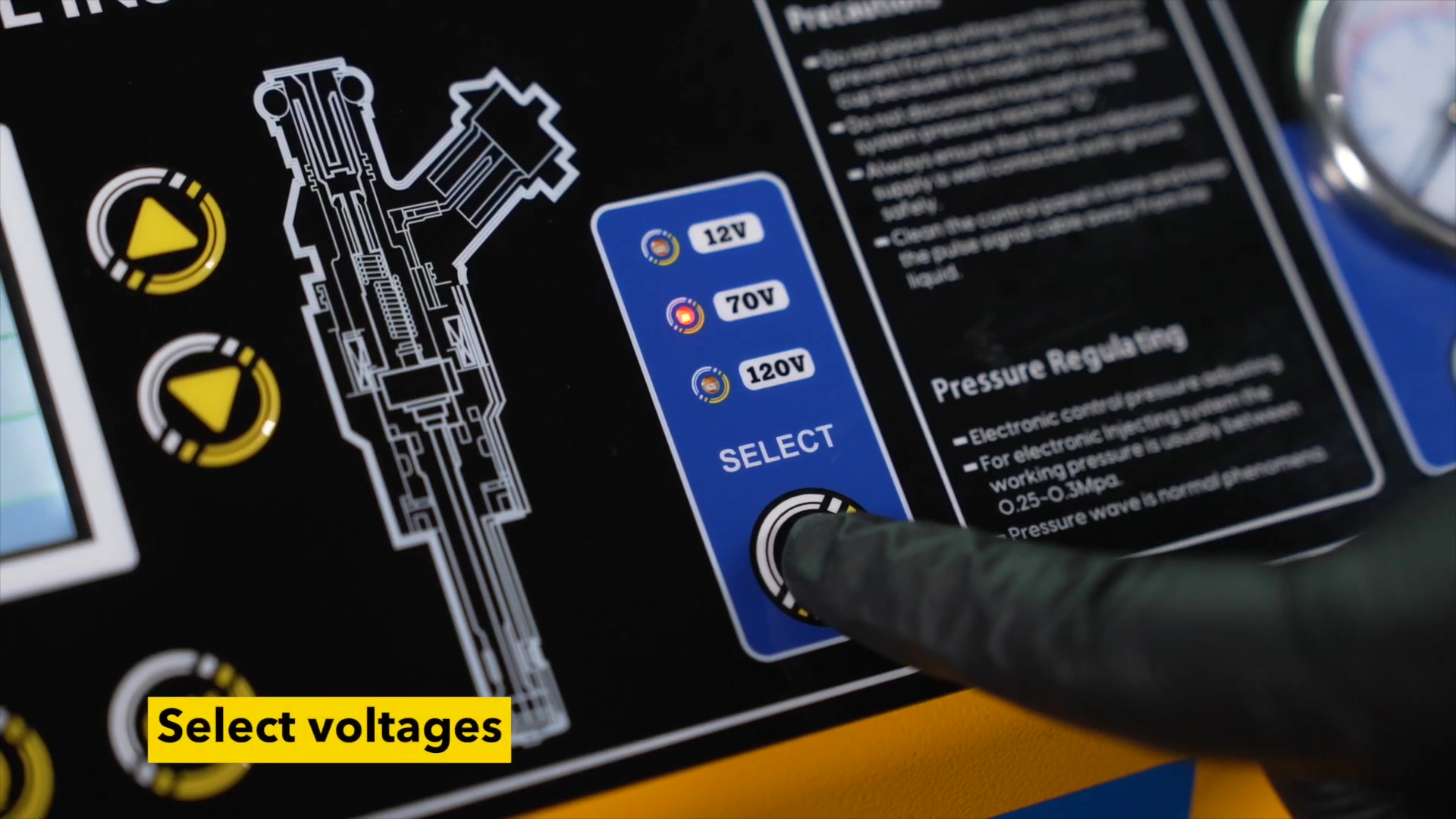
Step 9: Power on and select one verified fixed voltage
Confirm that the panel and leads are dry and that everyone is clear of the fixture. Connect the machine to a grounded outlet matching its nameplate, switch it on, and let the display initialize.
Use the voltage selector to choose the single verified 12 V, 70 V, or 120 V value already on the worksheet. Read the illuminated selection back before pressing Start. If it does not match, correct it while the machine is stopped.
Stop: If the fixed voltage is unknown, or an injector becomes hot, smells abnormal, fails to respond as expected, or produces a control fault, press Stop and isolate power. Do not test the next higher voltage.
Step 10: Prove the fixture with a leakage check
Select item 07, Leakage Test. Enter only the duration allowed by the injector specification and raise pressure gradually toward the documented test value, never beyond the injector limit or the CT500’s 0–0.8 MPa ceiling.
Watch the outlet pipe, rail, plugs, upper adapters, lower seats, O-rings, and cylinders before judging a nozzle. If any external joint wets, stop, reduce pressure to zero, isolate power where adjustment requires it, correct the fixture, dry the area, and restart. Only after every external joint stays dry should liquid at the nozzle be recorded as injector leakage.
Do not use the manual’s generic pressure or one-minute example as a universal rule. The exact injector acceptance method controls.
Completion check: External joints remain dry at a stable specified pressure, and every nozzle observation is recorded by original cylinder and machine channel.
Step 11: Compare spray under one matched condition
Choose a mode that fits the injector and question: idle, medium speed, high speed, accelerating, variable speed, or pulse injection. Record the menu item, fixed voltage, pressure, pulse width, time or count, fluid, adapter, and drain state. Keep all of them identical across the six channels.
From a protected viewing position, compare cone shape, direction, atomization, pulse consistency, response, and shutoff. Look for an off-axis stream, split pattern, jet where a cone is specified, delayed opening, unstable pulsing, or poor shutoff. Never touch the rail or place your face near a powered injector.
A dramatic mist is not a pass. The question is whether each injector repeatedly meets its specified pattern under the same recorded condition.
Completion check: Every injector has a pattern observation tied to its identity and the exact settings used.
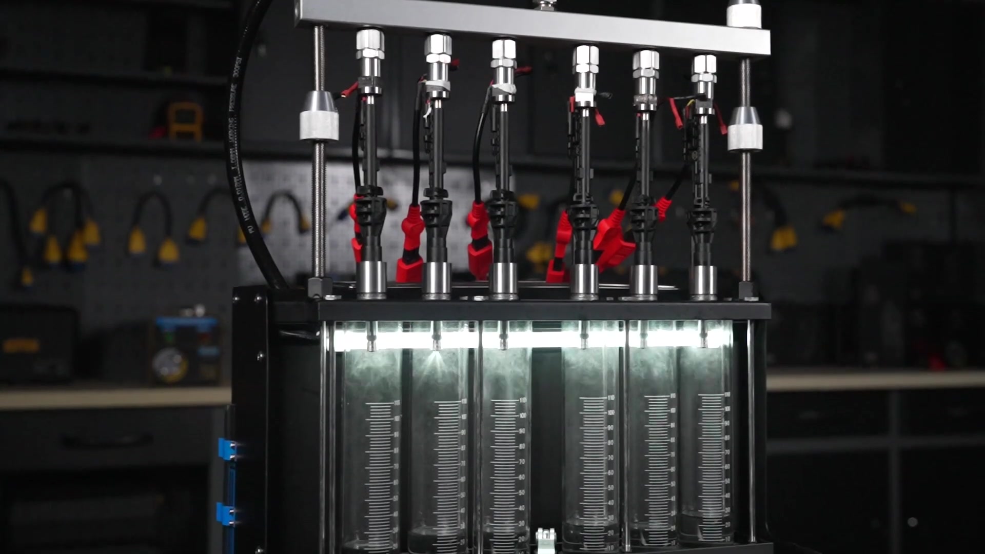
Step 12: Compare volume, repeat, and swap positions
Set the cylinder control to retain fluid, equalize the starting condition, and run one identical time or injection count for all installed injectors. Stop before any cylinder approaches its unsafe level. Let foam and wall droplets settle, then read each scale at eye height with the machine level.
Record raw volume for all channels. Apply the injector maker’s tolerance rather than automatically using a generic 2% figure. If one reading is different, repeat without changing settings. Next, swap that injector with a known-good fixture position and run the same test again.
If the abnormal result follows the injector, the injector is implicated. If it stays with the machine position, inspect the adapter, lead, seal, channel, valve, cylinder, and supply path. If it disappears, investigate setup repeatability before making a parts decision.
Pass condition: A difference repeats and follows the injector through a controlled position swap, or the fixture-side cause is identified.
Step 13: Repeat the baseline, depressurize, drain, and store
After cleaning or a fixture correction, repeat the original baseline with the same adapter, fixed voltage, pressure, pulse, time or count, fluid, channel state, and acceptance method. A before/after claim is valid only when its conditions match.
Press Stop, lower pressure to zero, switch off, and unplug before loosening the outlet pipe, distributor, plugs, or adapters. Drain or recover test fluid through its designated valve into a labeled container. Remove the distributor evenly to avoid side-loading injectors or glass. Drain the ultrasonic tank when required, return clean dry adapters and leads to the drawer, wipe the machine with a dry soft cloth, and store it in a dry ventilated place.
Save original-cylinder identity, adapters, settings, leakage observations, pattern notes, raw volumes, repeats, swaps, cleaning conditions, and the final decision.
Completion check: The gauge reads zero, power is isolated, no fitting is pressurized, liquids are secured in separate labeled containers, and the diagnostic record is complete.
How to interpret the result without overdiagnosing
The strongest CT500 result is not the first six-cylinder image. It is a matched result that survives a challenge to the fixture.
- External leakage means correct the fixture first; it does not prove nozzle leakage.
- A poor pattern or volume result that follows the injector through a position swap supports an injector-side problem.
- An abnormal result that stays with one channel points to its adapter, lead, seal, valve, cylinder, or supply path.
- Improvement after cleaning must be confirmed with the original settings.
- A balanced low-pressure result does not rule out a fault at engine high-side pressure, temperature, or vehicle waveform.
- A remaining vehicle symptom still requires control-signal, wiring, compression, ignition, intake, contamination, and rail-pressure diagnosis.
The machine is most useful when it prevents parts swapping. Preserve the setup and readings that distinguish the injector from the fixture and the vehicle.
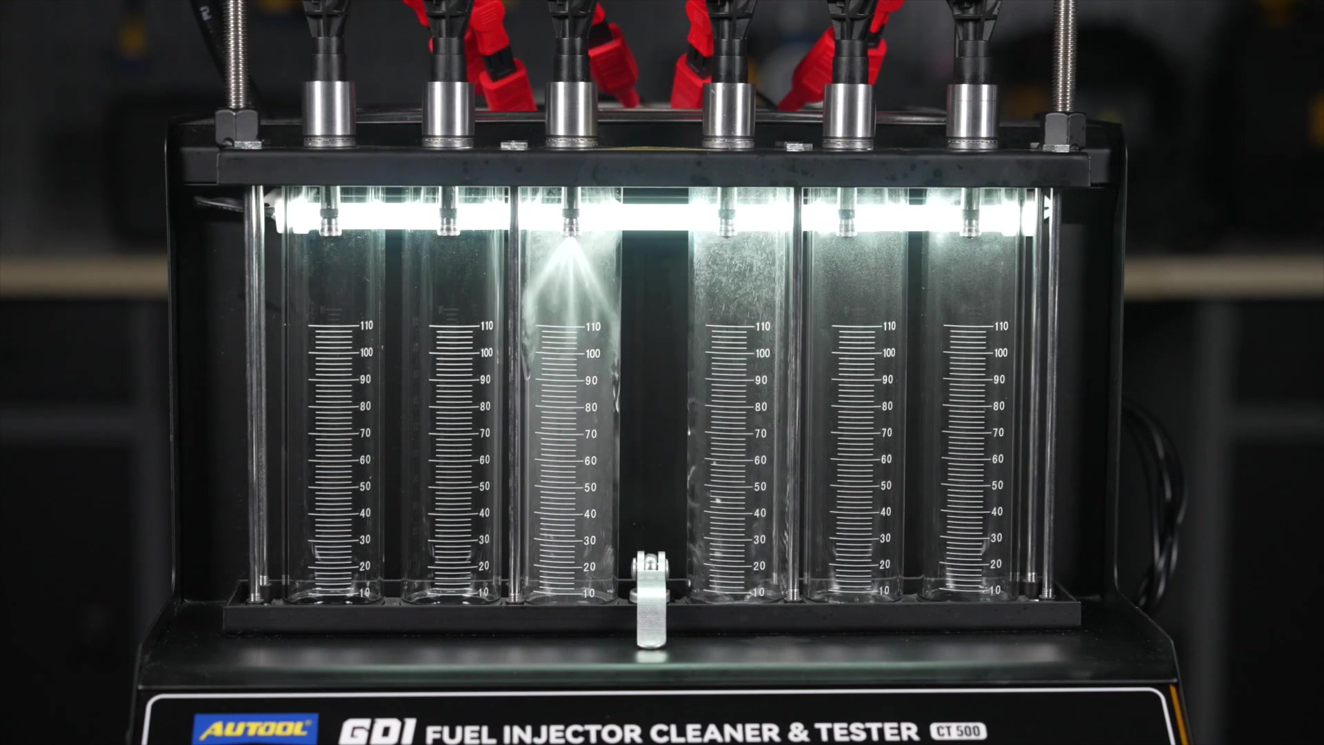
When to use pulse, wide-pulse, and continuous modes
Item 13 Pulse Injection Test allows documented pulse width and count. Item 14 Wide Pulse Injection Test extends that observation for compatible injectors. Item 15 Continuous Injection Test holds the injector open for an allowed interval; the CT500 manual recommends a working time below 30 seconds, but the injector’s lower thermal and duty limit still controls.
Use these functions only to answer a defined injector-specific question. Verify voltage, pressure, pulse width, count or time, and thermal limit before starting. Stop for abnormal heat, odor, current behavior, sound, spray, or control response. A machine menu option is not proof that a particular injector can safely tolerate it.
For comparisons, record the exact advanced mode and run one matched condition across every installed injector. Return to the original normal-mode baseline before deciding that cleaning changed the set.
When reverse flushing is appropriate
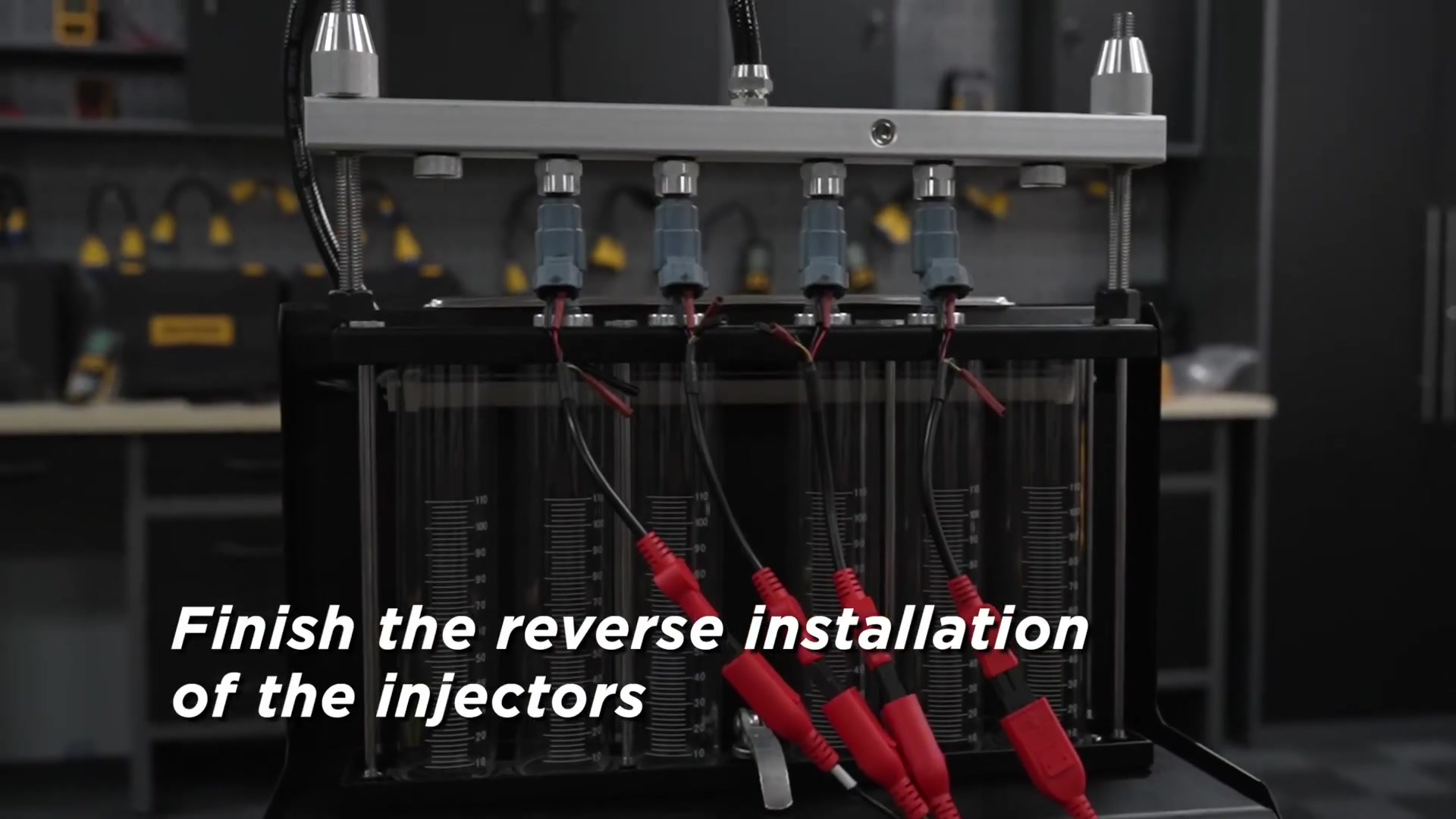
Reverse flushing is not a default cleaning step. Use item 11 only when the exact injector and adapter are approved for reverse installation and the reverse path can support the seals without damaging the inlet, tip, filter basket, or internal valve.
Document the reverse adapter, orientation, fluid, pressure, pulse, and duration. Stop and reduce pressure to zero before changing orientation. After the reverse cycle, reinstall the injector in its normal direction and repeat the original leakage, spray, and volume checks. The reverse-flush cycle is a process; the normal-direction retest is the result.
Common CT500 mistakes
Trying to heat the ultrasonic bath
The CT500 does not have an ultrasonic-heating function. Use approved liquid at its allowed condition; do not add an external heater or copy a heated CT450 procedure.
Treating 12 V, 70 V, and 120 V as a trial ladder
They are fixed choices for different electrical designs. Trial escalation can overheat or damage an injector and makes the comparison invalid.
Using 0.8 MPa as the normal test pressure
It is the machine ceiling, not a target. Use the injector’s specified pressure when it is inside the machine range.
Copying the generic 3 ms, 10-minute, 2000-count, or 2% examples
These illustrate machine controls. Exact injector, liquid, and service data determine settings and acceptance.
Mixing cleaning liquid and test fluid
The bath and pressurized circuit perform different jobs. Cross-use can damage the pump, hoses, seals, coating, or injector and invalidate results.
Calling any outside drip an injector leak
Adapter and O-ring leakage is a setup fault. Prove every external joint dry before classifying the nozzle.
Comparing changed settings
If adapter, voltage, pressure, pulse, time, fluid, drain state, or channel changes without being controlled, the result is not a valid before/after comparison.
CT500 operating checklist
Before cleaning:
- exact machine and supply voltage confirmed;
- injector identities, adapters, drive voltage, service pressure, pulse limits, and acceptance data recorded;
- machine level, grounded, dry, undamaged, ventilated, and away from ignition sources;
- approved cleaning liquid loaded before ultrasound;
- no external heating planned.
Before testing:
- electrical connections dry;
- correct adapters, seals, plugs, lock rods, outlet pipe, and leads installed;
- distributor level and injectors vertical;
- dedicated test fluid loaded and drain state recorded;
- one exact fixed voltage selected;
- pressure inside both the injector requirement and 0–0.8 MPa machine ceiling;
- external fixture proven dry.
Before deciding:
- spray and volume tests use identical conditions;
- abnormal observations repeat;
- a position swap separates injector behavior from channel behavior;
- before/after settings match;
- engine high-side and vehicle-side causes remain in the diagnostic plan.
Before disconnection:
- active function stopped;
- pressure at zero;
- power off and plug removed;
- cleaning and test liquids recovered into separate labeled containers;
- all observations and raw readings saved.
Frequently asked questions
Does the CT500 heat its ultrasonic tank?
No. It provides ultrasonic cleaning without a bath-heating function. Do not transfer a heated CT450 procedure or add an external heater.
Can the CT500 test diesel injectors?
No. Its gasoline-injector adapters and drive choices do not make it a common-rail diesel injector bench.
Does GDI support mean full engine-pressure testing?
No. It supports compatible GDI-family injectors mechanically and electrically for low-pressure comparative work within the CT500’s 0–0.8 MPa machine range. It does not reproduce the engine’s high-side pressure or complete waveform.
What voltage should I select?
Use the exact 12 V, 70 V, or 120 V requirement for the identified injector. If it is unknown, do not energize the injector. Never step upward to see what makes it operate.
What pressure should I use?
Use the exact injector service-test pressure when it is within the CT500’s range. The 0.8 MPa figure is a ceiling, not a default.
Can I test fewer than six injectors?
Yes, when the selected adapters support them and every unused distributor outlet is closed with the correct plug. Preserve numbered positions and traceability.
Is the manual’s 2% example a universal flow limit?
No. Use the injector manufacturer’s tolerance. Record raw readings, repeat the run, and swap positions before deciding whether a difference belongs to the injector.
What makes a CT500 result trustworthy?
Known injector identity, exact adapters and fixed voltage, approved separate fluids, a documented pressure and pulse plan, a dry fixture, identical comparison conditions, repeat runs, position swaps, and a complete record. That discipline turns six measuring cylinders into evidence you can act on.











Comments 0
Questions, fixes, and real-world diagnostic notes from readers.
Be the first to share a diagnostic result or ask a follow-up question.