
How to Use the AUTOOL ATF702 Transmission Fluid Exchanger

Use the AUTOOL ATF702 only after you have identified the exact ATF, found the approved transmission cooler-line connection, and confirmed the vehicle-specific level procedure. A successful exchange depends on four controls: correct fluid, proven line direction, a leak-free closed circuit, and a final level set at the required temperature and selector condition.
ATF702 is a manually controlled, 12 V transmission fluid exchanger. You select the flow mode with two valves, watch the new and used fluid through separate windows, and balance the exchange instead of handing those decisions to an automatic program. This guide covers the machine-side workflow while the vehicle manufacturer’s service information controls cooler-line access, operating state, gear sequence, capacity, temperature, level, torque, adaptation, and road test.
In this guide
- What the ATF702 does
- Before you start
- Understand the ATF702 before connecting a vehicle
- ATF702 step-by-step operating procedure
- Optional circulation-cleaning mode
- Empty the used-fluid tank safely
- How to judge a reliable result
- Common problems and corrections
- After-use maintenance and storage
- ATF702 FAQ
- The reliable ATF702 workflow
What the ATF702 does
The AUTOOL ATF702 connects in series with a supported automatic transmission cooler circuit. Its pump supplies new ATF while the transmission sends used fluid through the return path. Two pressure gauges, two fluid windows, tank-level windows, two mode valves, a flow-control valve, an emergency stop, and manual switches let the operator see and control the process.
It is not a universal power-flush command. It cannot identify the correct ATF, prove that a cooler-line location is approved, decide whether a transmission should be exchanged, set the final level, or replace diagnosis. Do not exchange a transmission with an unidentified fluid requirement, a known internal failure, heavy debris that calls for inspection, an active leak, damaged cooler lines, or a manufacturer prohibition on this service method.
The machine manual includes a separate circulation-cleaning mode. Treat that as optional. Never add a generic cleaning chemical unless the vehicle manufacturer, the chemical supplier, and the instructions for your delivered ATF702 revision all authorize the exact product, quantity, materials, and process.
Before you start
Open the AUTOOL manual download center and match the manual to the machine in front of you. Obtain the vehicle procedure for ATF specification, service condition, cooler-line access, line-flow identification, lifting, gear selection, temperature monitoring, level setting, fastener torque, adaptation, leak inspection, and road testing.
Prepare:
- enough sealed, exact-specification ATF for the vehicle procedure, priming, exchange, and final adjustment, plus a contingency amount;
- the ATF702 adapter case, both machine hoses, the transparent external-suction tube, caps and clean catch containers;
- vehicle-approved replacement clips, seals, O-rings, washers, retainers, and cooler-line fittings;
- a scan tool capable of reading the required transmission-fluid temperature and service data;
- eye and hand protection suitable for hot petroleum fluid, spill control, drain containers, labels, and an approved waste-ATF container;
- wheel chocks, an approved lift or support equipment when required, lighting, and tools for the vehicle connection.
Place the ATF702 upright on a level, stable floor. Keep the work area ventilated and free of ignition sources. Allow the cooler circuit to reach the vehicle procedure’s safe disconnection condition. Apply the parking brake, chock the wheels, and support the vehicle only at approved points.
Stop: Do not proceed with damaged power leads, a blown or bypassed fuse, split hoses, cloudy sight windows, loose fittings, contaminated tanks, a stuck valve, unreadable labels, an inoperative emergency stop, an unknown battery voltage, or insufficient correct ATF.
Understand the ATF702 before connecting a vehicle
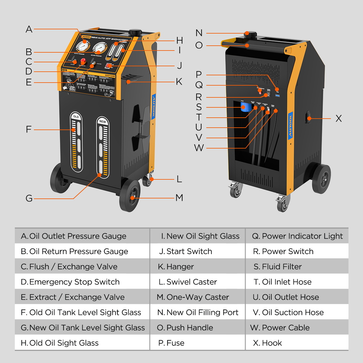
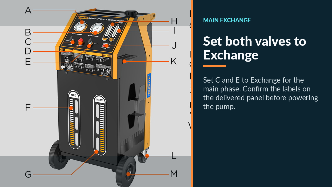
Face the control panel and identify the output-pressure gauge, return-pressure gauge, left Flush/Exchange valve, right Extract/Exchange valve, emergency stop, pump/start control, main power switch, and new/used fluid windows. Then locate the new-fluid fill opening, external-suction connection, new-fluid and used-fluid level windows, labelled outlet and return hoses, in-line return-flow valve, fuse, cable, and hose storage points.
The left valve chooses between circulation cleaning and exchange. The right valve chooses between external extraction and exchange. The exact labels on the delivered panel control; do not rely on memory, cabinet side, hose color, or another ATF model.
Trace the intended exchange circuit before adding power:
- new ATF leaves the machine through its labelled outlet path;
- that path feeds the vehicle’s cooler-circuit inlet;
- the transmission’s cooler-circuit outlet sends used ATF back through the machine return path;
- the used-fluid window and tank receive the return flow.
The pressure gauges are diagnostic indicators, not universal targets. Normal readings vary with the vehicle circuit, fluid temperature, operating condition, adapters, and hose routing. Never restrict a line merely to chase a number.
ATF702 step-by-step operating procedure
Step 1: Confirm that exchange is the right service
Interview the driver and document the complaint, maintenance history, fluid type if known, leaks, warning lamps, shift quality, and prior additives. Scan all relevant modules and record transmission codes, temperature, and service data. Inspect the pan, fluid, cooler lines, connectors, and external leaks as access permits.
If the transmission has severe slipping, loss of drive, burnt fluid with heavy debris, coolant contamination, an active internal fault, or an unknown service history that changes the diagnostic plan, stop and diagnose before connecting an exchanger. Fluid exchange is maintenance, not a repair for failed friction elements, valve-body faults, solenoids, pumps, bearings, or coolers.
Completion check: The service method is permitted, the baseline is recorded, and there is no fault that must be repaired or inspected first.
Step 2: Identify the exact ATF and final-level method
Use the vehicle identification, transmission code, build data, and current manufacturer service information to select the exact ATF specification. Do not choose by color, smell, “multi-vehicle” wording alone, or the fluid already in the machine.
Record the specified capacity range, target fluid-temperature window, engine state, selector position, fill-plug or dipstick method, overflow behavior, scan-tool requirement, and any adaptation procedure. These values govern how much you prepare and how you finish the job.
Completion check: The ATF specification and final-level procedure are written on the job card and match the actual transmission.
Step 3: Inspect and segregate the machine
Confirm that the new-fluid side is clean and contains only compatible fluid. Empty the used-fluid side before it approaches capacity. Inspect the hoses internally where possible, fittings, sight windows, valve movement, in-line flow control, power cable, clamps, fuse, switches, and emergency stop.
If the previous job used a different or incompatible ATF, follow an approved machine decontamination process before loading the next fluid. Never “push the old type out” through the customer’s transmission. Label the machine and containers when a shop handles multiple fluid families.
Completion check: New and used paths are identified, capacity is available, and cross-contamination controls are in place.
Step 4: Load the correct new ATF
With machine power off, both clamps disconnected, and the cabinet level, clean around the fill opening. Add the planned ATF through the new-fluid inlet using clean, dedicated transfer equipment. Keep caps, funnels, hands, and containers free of lint, water, dirt, and other fluids.
The machine also supports drawing ATF from an external container through the transparent tube. Use that route only with the valve positions shown on the delivered panel and manual: left at Exchange, right at Extract. Keep the tube submerged in clean fluid and never allow the pump to ingest air.
Do not fill to an assumed fixed amount. Leave enough tank margin for the machine revision and monitor both level windows throughout the job.
Completion check: Enough exact-specification ATF is available, the new side is uncontaminated, and neither tank can overrun during the planned exchange.
Step 5: Select adapters and open the approved cooler-line point
Use the vehicle procedure to locate a serviceable connection between the transmission and its cooler circuit. Let the circuit reach a safe disconnection condition, clean the area, release residual pressure as specified, and place containment below it before opening.
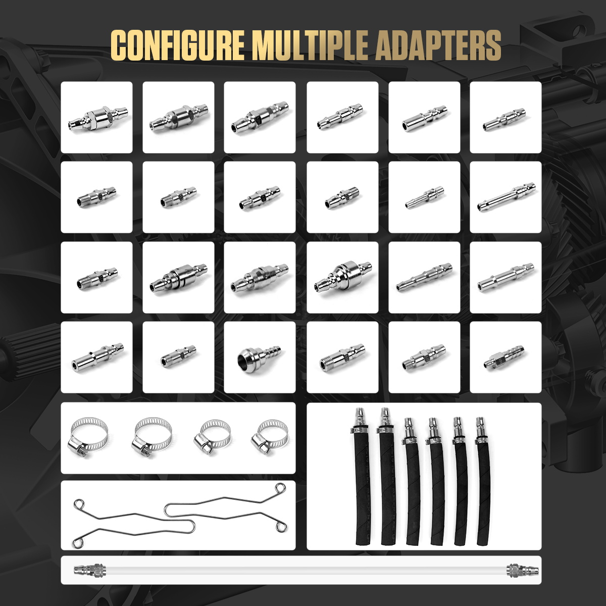
Select adapters by thread, flare, seal type, diameter, depth, locking method, and flow area—not by appearance alone. Inspect every O-ring and sealing face. Do not force an adapter, stack improvised fittings, omit a retainer, or reduce the circuit with an obviously undersized passage.
Cap open components immediately. Preserve original clips and fittings for reassembly, or replace them where the vehicle procedure requires.
Completion check: Both vehicle ends and both machine adapters match, seal, lock, and retain full flow without side load.
Step 6: Prove the transmission outlet and inlet
The transmission outlet must connect to the machine return/used-fluid path; the vehicle inlet must connect to the machine outlet/new-fluid path. Do not infer direction from hose position, color, temperature before flow, or another vehicle.
Use the manufacturer’s stated flow direction or its approved identification method. If the vehicle and machine procedures permit a brief running flow check, contain the open ends, keep the pump from running dry, keep people clear of fans and belts, and stop as soon as direction is proven. Never run an open line without control.
Stop: If flow direction is uncertain, obtain the correct service information. Reversed connections can empty the transmission, deadhead a circuit, upset pressure, or send used fluid into the new-fluid path.
Completion check: The two vehicle ends are positively labelled “transmission outlet” and “transmission inlet.”
Step 7: Connect and prove the closed fluid circuit
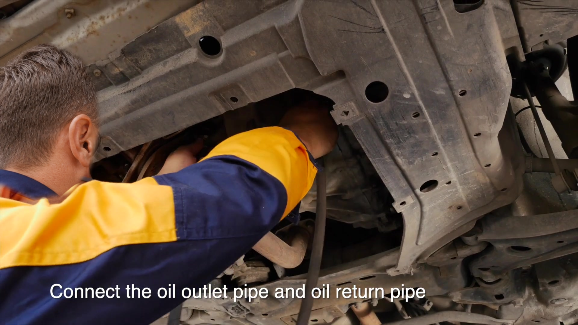
Connect the transmission outlet to the ATF702 return/used-fluid hose. Connect the machine outlet/new-fluid hose to the vehicle inlet. Lock every quick connector and vehicle retainer, then pull-test each connection by hand.
Route hoses with broad bends and enough slack for engine movement. Keep them away from exhaust parts, the radiator and cooling fan, belts, pulleys, steering shafts, axles, wheels, lift arms, and sharp edges. Support the hoses so their weight does not load a cooler fitting.
Before running either pump, verify the circuit aloud from transmission outlet to machine return, through the machine, out of the machine outlet, and back to the vehicle inlet.
Completion check: The circuit is closed, direction is proven, connectors are locked, and hose routing is protected from heat, movement, abrasion, kinks, and tension.
Step 8: Connect 12 V power and prime the new-fluid path
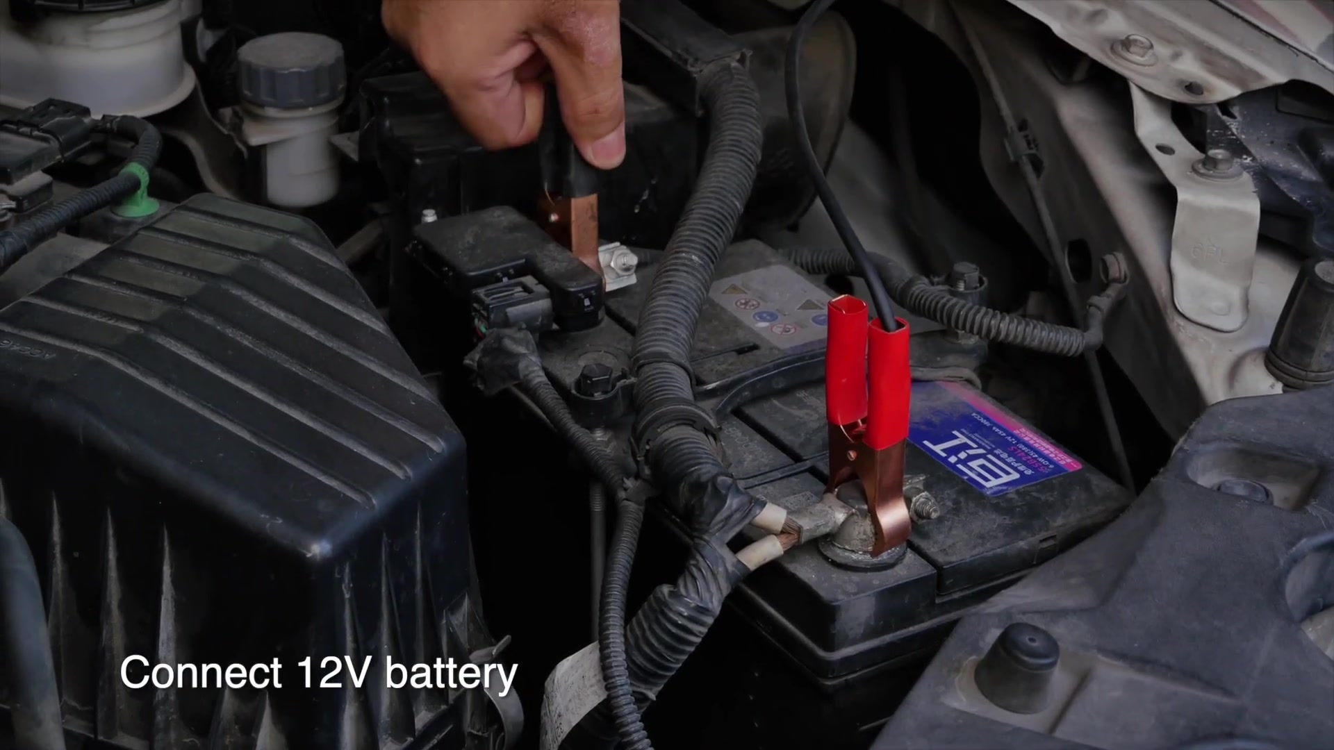
Set the pump and main power switches off and release the emergency stop according to its label. Confirm the power source is a suitable 12 V system. Connect the red clamp to positive and the black clamp to negative; place both leads where engine and workshop movement cannot catch them.
Prime the new-fluid path as shown in the delivered manual, directing the machine outlet into a clean, controlled container until new ATF appears as a solid, air-free stream. Stop the pump, reconnect the closed vehicle circuit, clean any spill, and recheck the new-fluid level.
Never reverse polarity, short the clamps, place a clamp on a dirty or unstable contact, run the pump dry, or leave an open outlet unattended.
Completion check: Polarity and cable routing are safe, the new-fluid path is air-free, and the vehicle circuit is restored and sealed.
Step 9: Run a low-risk leak and flow check
Set the valves for the next approved phase with power off. Start the vehicle only in the state specified by its service procedure. Keep the service brake applied and driven wheels stationary unless the manufacturer procedure explicitly requires rotation on equipment designed for that condition.
Watch both gauges, all connections, both fluid windows, tank levels, and hose behavior. A brief initial delay may reflect circuit filling, but persistent no-flow, pulsing air, a collapsing hose, a sharp pressure change, or a leak is a stop condition.
Stop: Shut down the vehicle and machine immediately for leakage, hose movement, abnormal noise, pressure behavior outside the vehicle or machine limit, aerated flow, wrong-direction evidence, or loss of new-fluid supply.
Completion check: Flow direction remains correct, both sides are liquid-full, and every joint stays dry under the approved operating condition.
Step 10: Perform the controlled ATF exchange
For the main exchange, set both ATF702 mode valves to Exchange as marked on the panel. Turn on the machine pump so new fluid is established in the new-fluid window, then operate the vehicle exactly as its service procedure requires for cooler flow.
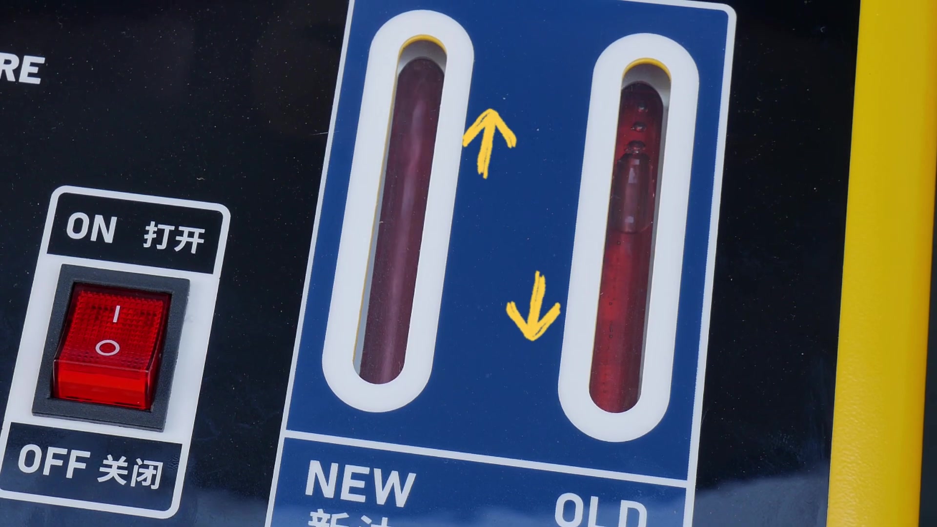
Observe new and used flow continuously. If used fluid returns faster than new fluid enters, make small corrections with the return-path flow valve to bring the rates into balance. Do not close it abruptly, deadhead the cooler circuit, or use restriction to mask a wrong connection or weak new-fluid supply.
Follow only the vehicle-approved selector sequence. The machine manual’s short dwell in each gear is not universal. Keep the service brake applied; keep personnel clear; never allow uncontrolled wheel movement; and use a suitable lift or dynamometer if an approved procedure actually requires driven-wheel rotation.
Completion check: Flow is continuous and balanced, tank levels remain within limits, pressure behavior is stable, hoses remain secure, and the vehicle follows its approved operating sequence.
Step 11: Decide when to stop the exchange
Use the job plan and measured fluid movement as the primary limit. The used-fluid window helps you see contamination and a change toward the fresh-fluid appearance, but color alone cannot prove an exchange percentage, correct chemistry, or correct final level.
Stop before the prepared new-fluid supply runs low, the used-fluid tank reaches its limit, air enters either stream, the vehicle’s exchange quantity is exceeded, or any abnormal condition develops. Avoid chasing perfectly clear return fluid with unlimited new ATF.
Turn off the machine pump, then stop the vehicle in the sequence required by its service information. Isolate 12 V power before disturbing any hose.
Completion check: The planned quantity and condition gate are met without tank overrun, air ingestion, leakage, abnormal pressure, or fluid mismatch.
Step 12: Restore the vehicle cooler circuit
Allow pressure and temperature to reach the specified service condition. Place containment below the connections, release each machine coupling carefully, and cap machine hoses immediately. Restore the original cooler-line path with the specified new seals, clips, retainers, and fittings.
Seat every connector fully and apply the specified torque. Clean all ATF from the line, case, undertray, exhaust area, and surrounding parts so a later leak cannot hide in residue. Remove temporary caps and verify that no tool or plug remains.
Completion check: The original circuit is restored with correct retention and torque, and the area is clean enough for a meaningful leak inspection.
Step 13: Set the final level at the specified temperature
Follow the vehicle procedure from the beginning; do not default to Park, a cold dipstick reading, or a generic “engine running” rule. Monitor transmission-fluid temperature with the specified method, hold the vehicle level, use the required selector state and engine state, and add or drain only the exact ATF needed.
If the transmission uses a standpipe or overflow plug, observe its temperature window, opening sequence, seal replacement, and torque. If it uses a dipstick or scan-guided fill procedure, follow that method exactly. An exchanger’s balanced windows do not replace this step.
Completion check: Fluid level is correct within the required temperature window and the fill/level hardware is sealed and torqued.
Step 14: Verify the repair and record the result
Run the engine and inspect the restored cooler circuit, level point, pan, and disturbed components for leaks. Confirm normal selector engagement and scan data before road testing. Perform adaptation or relearn only when the vehicle procedure calls for it.
Road-test only after level, retention, underbody clearance, and static leak checks pass. Use the manufacturer’s drive cycle rather than a fixed distance. Recheck for leaks and, when required, recheck the level at the specified temperature after the drive.
Record the ATF specification and batch, quantity loaded into the machine, estimated or measured quantity exchanged, quantity added or removed during final setting, final temperature, fault-code status, adaptations, and leak-check result.
Completion check: The transmission operates as expected, no leak or warning is present, the final level remains correct, and the service record is complete.
Optional circulation-cleaning mode
Use this mode only when all three instructions agree: the vehicle maker permits it, the chemical supplier approves the exact transmission and materials, and the delivered ATF702 manual specifies the same introduction method. If any approval is missing, skip chemical cleaning and perform only the approved ATF exchange.
With the machine and vehicle already connected in the proven direction, the ATF702 manual uses the transparent tube at the external inlet, left valve at Exchange, and right valve at Extract to meter an approved cleaning fluid. After introduction, the pump is switched off, the transparent tube is removed, the left valve is placed at Clean, and the right valve at Exchange before vehicle-powered circulation.
The amount, circulation time, temperature, selector sequence, and need for a subsequent full exchange come from the approved procedures—not a universal timer. Maintain the same hose, wheel, leak, pressure, tank, and supervision controls used during exchange.
Stop: Do not circulate an unidentified additive, mix chemistries, exceed an approved dose, leave the vehicle unattended, or continue through a leak, pressure anomaly, shift fault, foam, aeration, or abnormal noise.
Empty the used-fluid tank safely
Move the vehicle out of the fluid circuit and cap the machine hoses. Place a compatible waste container below the discharge path with enough free capacity. Keep the ATF702 upright, wear splash protection, and follow the valve diagram on the delivered machine.
The manual’s used-fluid discharge path sets the left valve to Exchange and the right valve to Extract, joins the transparent tube at the machine external-suction connection to the return hose, and directs the outlet hose through the suitable adapter into the waste container before the pump is switched on. Confirm that exact routing against the panel and manual before starting.
Watch the container and tank level continuously. Stop before the pump draws air, then isolate power, relieve residual fluid into the container, cap the hoses, label the waste, and manage it under local rules. Never discharge ATF to the ground, a drain, or an unlabelled container.
How to judge a reliable result
The job passes only when all three gates pass:
| Gate | Evidence required |
|---|---|
| Fluid circuit | Correct ATF, proven direction, balanced flow, planned exchange quantity, no air, no abnormal pressure, and no tank overrun |
| Vehicle restoration | Original cooler path restored with correct seals, retention and torque; no static or running leak |
| Transmission state | Level set by the exact temperature procedure, normal engagement and scan status, required adaptation completed, and post-drive check passed |
A return stream that looks clean is useful visual evidence, but it cannot overrule the quantity plan or final-level procedure. Likewise, equal-looking tank movement does not prove that trapped air, an external leak, or an incorrect fluid type is absent.
Common problems and corrections
No return flow appears
Stop the vehicle and pump. Check the approved operating state, line direction, adapter engagement, kinked hoses, closed or wrong valve position, empty new-fluid supply, air in the pump path, and cooler-circuit restrictions. Do not rev the engine or close a valve to force a reading.
New fluid moves slower than used fluid
Confirm that the new-fluid path is primed, the correct valve positions are selected, the supply has not run low, and the hose is not restricted. If the system is otherwise correct, make only a small return-flow adjustment while watching both streams. Stop if balance cannot be maintained.
Pressure changes sharply
Stop immediately. Inspect for a kink, closed valve, wrong adapter, reversed connection, blocked cooler, incorrect vehicle state, thick/cold fluid, or deadheaded path. The gauges help identify a problem; they do not authorize a universal target pressure.
Bubbles or foam appear
Stop before air reaches the transmission. Refill the new side if low, reseal the external-suction tube if used, reprime the machine, inspect connections for air entry, and verify that incompatible or foaming chemistry has not been introduced.
Fluid color does not become identical
Do not keep consuming ATF solely for color. Check the planned quantity, circuit design, starting contamination, ATF color, and vehicle limit. Some fluid remains in internal circuits, and appearance varies with lighting and formulation. Finish only by the controlled quantity and final-level gates.
After-use maintenance and storage
Disconnect 12 V power and clean spills promptly with materials compatible with the cabinet, hoses, and seals. Inspect fittings, hose jackets, clamps, switches, fuse holder, cable insulation, windows, wheels, fasteners, and storage hooks. Replace damaged or aged electrical and fluid parts before the next job.
Keep the new-fluid path capped and segregated. Empty used ATF before storage limits are reached. Protect metal surfaces from corrosion without contaminating the fluid circuit. Store the machine upright in a dry, ventilated place away from heat, moisture, direct weather, and ignition sources.
Maintain a log of fluids handled, decontamination, hose or seal replacement, electrical inspection, faults, and repairs. Long idle periods require power disconnection and a clean, dry fluid path before recommissioning.
ATF702 FAQ
Is the ATF702 fully automatic?
No. It is a semi-automatic exchanger with mechanical mode valves, manual observation, and manual flow balancing. The operator remains responsible for correct routing, valve position, fluid supply, tank limits, pressure behavior, and shutdown.
Can I use ATF color to choose the fluid?
No. Different specifications may share a color, and aged fluid changes appearance. Identify the transmission and use its current service specification.
Must every exchange include chemical cleaning?
No. Circulation cleaning is optional and may be prohibited. Use it only with explicit vehicle, chemical, and machine approval.
Do both valves go to Exchange during the main exchange?
Yes, the exact ATF702 manual and quick guide show both mode valves at Exchange for the main exchange phase. Confirm the labels on your delivered revision before powering the pump.
How do I know which cooler line is the outlet?
Use the vehicle manufacturer’s flow information or its approved test. Never guess from left/right position, hose color, or another model.
When is the exchange complete?
When the planned quantity and condition gate are met without an abnormality, then the cooler circuit is restored and the exact temperature-dependent final level and leak checks pass. Sight-window color alone is not enough.
Can the final level be checked in Park on every vehicle?
No. Selector position, engine state, temperature, and method differ. Follow the exact transmission procedure.
The reliable ATF702 workflow
Plan the fluid and final-level method before opening a line. Inspect and segregate the machine, load only the exact ATF, prove cooler-flow direction, build a sealed circuit, connect correct 12 V polarity, prime the new-fluid path, and leak-check at low risk.
Set both valves to Exchange for the main service, maintain continuous balanced flow, and stop by the planned quantity and condition gates—not a percentage, timer, or color promise. Restore the cooler circuit correctly, set level at the specified temperature, verify operation and leaks, document the result, then discharge and store the machine cleanly.











Comments 0
Questions, fixes, and real-world diagnostic notes from readers.
Be the first to share a diagnostic result or ask a follow-up question.