
How to Use the FXTUL MV50 Articulating Borescope

The FXTUL MV50 is an articulating motorcycle and automotive borescope. This guide turns the current model-specific controls and official operating sequence into a practical start-to-finish workflow.
Quick answer: Cool and secure the target area, confirm the MV50 produces a clear live image, guide the probe without forcing it, inspect from a known orientation, save a location view plus a detail view, then neutralize and withdraw the camera slowly.
In this guide
Before you start
Begin with the engine, exhaust, catalyst, pipe or cavity fully cooled and the vehicle secured. Open only an access point allowed by the vehicle procedure. Know what is on the other side of the opening: a borescope can reveal a surface, but it must not contact moving parts, live terminals, fuel vapor, corrosive liquid or a passage too tight for the head.
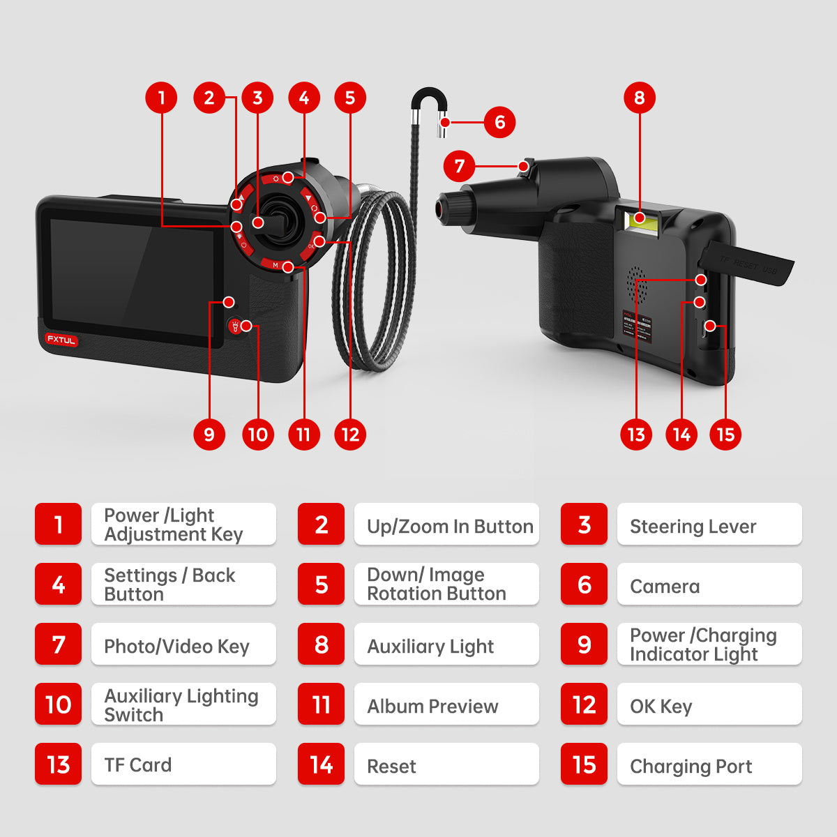
- confirm that the model label reads FXTUL MV50 and identify its display, articulation control and capture buttons;
- inspect the lens window, camera head, bending section, cable and connectors for damage or contamination;
- compare the camera-head diameter and bending clearance with the planned opening before insertion;
- choose a known start orientation and decide how you will describe the access point and viewing direction;
- keep the screen, main unit and electrical connectors dry even where the probe itself has a stated ingress rating; and
- prepare a clean, approved wipe and a loose storage coil for after the inspection.
Keep the manual supplied with the MV50 beside the exact access, removal and restoration procedure for the inspected component. The physical unit labels, delivered manual and vehicle service information control if an older web image differs.
MV50 controls and specifications
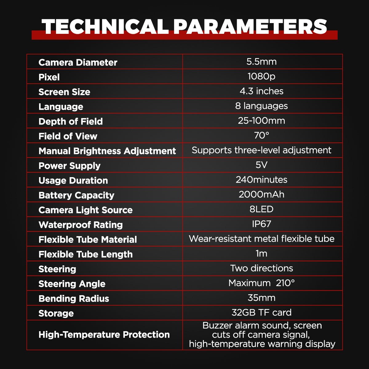
Treat the camera-head diameter, depth of field, articulation range, temperature boundary and waterproof boundary as separate limits. An IP rating for the probe does not make the screen waterproof, and a temperature alarm or shutdown is not permission to inspect a hot engine.
How to use the MV50
Step 1: Confirm the exact MV50 and inspection target
Match the unit and product label to FXTUL MV50, then inspect the display, articulation control, probe, camera head, cable, charging connection and 32GB storage. Identify the exact cavity and access route from current vehicle or equipment service information. Remove parts only by that procedure; do not use the probe to discover an unknown route by force.
Before moving on, verify the opening is large enough for the camera head and bending section, and confirm that the target is no longer hot.
Step 2: Secure, isolate and cool the work area
Park or support the vehicle or machine securely, switch it off and isolate any system that could move, energize, pressurize or heat the inspection area. Let an engine, exhaust, catalytic-converter area or other hot component cool completely. FXTUL recommends using the MV50 below 75°C and not exposing the hose above 75°C, so confirm the target is safely cool before insertion.
Step 3: Open the approved access point and prevent contamination
Follow the exact service procedure to remove the plug, sensor, trim, duct or cover that provides inspection access. Protect the opening from dirt and loose hardware, account for seals and fasteners and keep foreign objects out. If the access route cannot accept the 5.5mm-class camera head without contact or force, choose another approved method.
Step 4: Inspect and power the borescope
Check the display housing, buttons, articulation control, probe sheath and camera window for damage, contamination or sharp bends. Keep the main unit dry. Power the MV50 on, confirm the live image and storage status and set the language, date and time before the probe enters the cavity so captured evidence can be identified later.
Step 5: Set a clear reference image before insertion
Clean the camera window with a suitable non-abrasive method and point it at a nearby known surface. Adjust the three-level LED illumination, display brightness and zoom only enough to produce a clear reference image. Excess light can wash out a close surface, while digital zoom enlarges pixels and does not create additional physical detail.
Step 6: Guide the probe along the known route
Return the articulation control toward neutral and feed the probe slowly while watching both the cable and live view. Maintain gentle control at the access point, keep the cable away from sharp edges and do not use the camera head as a pick, pry bar or obstruction remover. Stop immediately if resistance increases or the route becomes uncertain.
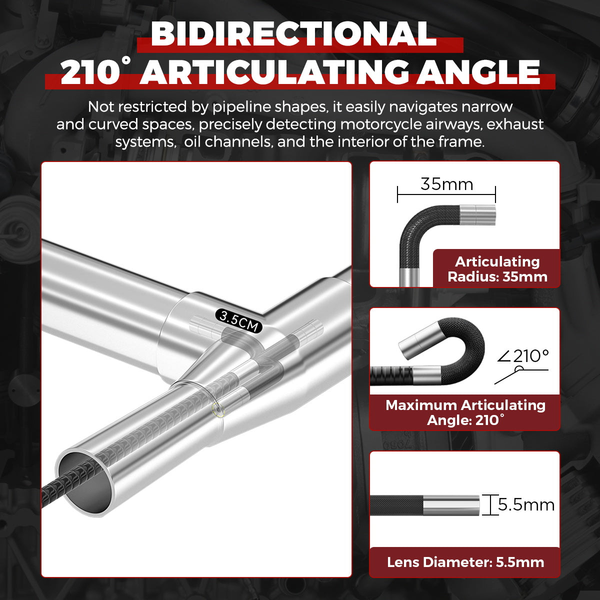
Step 7: Use the 210-degree articulation deliberately
Once the head has clearance, turn the handle gradually to direct the camera through its bidirectional articulation range. Use small inputs and observe the live image rather than driving the control against its limit. Reposition the shaft before requesting more angle; never force the head around a corner or withdraw it while strongly articulated.
Step 8: Control light, distance and orientation
Move the head in small increments and adjust LED level for each surface. Start with an orientation landmark such as an opening, fastener or component edge, then record broader context before close detail. Use the screen's zoom only as a viewing aid and capture several angles when oil film, reflection, soot or shadow could imitate a defect.
Step 9: Capture traceable photos and video
Use the one-touch photo or video function to record the access point, target identity, orientation landmark, overview and relevant close-up. Review critical files on the MV50 before leaving the area and note which cylinder, passage, side or component each file represents. An image supports inspection but does not by itself establish the mechanical cause of a symptom.
Step 10: Neutralize and withdraw without snagging
Return the articulation control toward neutral before withdrawal, then remove the probe slowly along the same approved route while watching for a seal lip, thread, sharp edge or obstruction. Never pull hard on a snagged probe. If it does not withdraw freely, stop and restore visual control or follow the component access procedure.
Step 11: Clean, review and restore the vehicle
With the unit off, wipe the probe and camera head using a material-compatible method; do not immerse or wash the display unit. Review and transfer the saved files as required, then restore every removed seal, sensor, plug, fastener and cover to the exact service specification. Complete any required leak, fault-code or functional check before returning the vehicle to service.
Before closing the access point, confirm the camera head and cable are intact, the saved images can be located, and no wipe, cap or tool remains in the work area.
Read and verify the result
Interpret the image only after you can locate it. First save a wider frame that shows the inspection area, then a closer frame that shows the suspected condition. Change one variable at a time—viewing angle, distance or LED brightness—so glare, shadow and debris are not mistaken for damage.
- A sharp, repeatable feature seen from more than one nearby angle is stronger evidence than one blurred frame.
- Bright metal, oil film and wet deposits can reflect the LEDs; reduce brightness or change angle before calling a mark a crack.
- Carbon, corrosion, scoring, leakage traces or a foreign object can guide the next diagnostic step, but an image alone does not identify the root cause.
- Keep the original photo or video with the access point, viewing direction and vehicle condition so a later comparison is meaningful.
Stop if the target is still hot, the cable meets unexplained resistance, the image disappears, the head cannot return toward neutral, liquid approaches the main unit, or the probe could be trapped by a moving component. Do not pull harder; make the area safe and recover the probe along its insertion path.
Common mistakes and care
- Use the MV50 only after the target has cooled; FXTUL recommends operation below 75°C and says not to expose the hose above 75°C.
- The current IP67 claim applies to the lens or probe area described by FXTUL, not permission to immerse, hose or pressure-wash the display unit.
- Do not force the probe, articulation control or camera head through an unknown route, across a sharp edge or against an obstruction.
- Return the articulation toward neutral before withdrawal and stop if the probe snags.
- Keep the probe clean and avoid direct contact with water, oil and corrosive liquids beyond the exact limits stated for the camera area.
- A borescope image documents visible condition; confirm diagnosis with vehicle service information and appropriate tests.
- Do not force the probe around a corner, twist the cable to steer, bend the camera head by hand or hold the articulation control at its travel limit.
- Do not use maximum LED brightness by default; glare can hide the texture you are trying to inspect.
- Do not describe an internal mark as a confirmed failed part until its location and diagnostic significance are verified by the vehicle procedure.
- After use, return the head toward neutral, clean and dry the approved probe section, and store the cable in a loose coil.
Frequently asked questions
Can the MV50 inspect a hot engine?
No. Let the engine and target area cool completely. A temperature alarm or protective shutdown is a last-resort protection feature, not a normal operating temperature.
Why is the image bright but still hard to interpret?
The LEDs may be reflecting from metal, oil or moisture. Reduce brightness, adjust the working distance and change the viewing angle while keeping the location reference.
Is the whole borescope waterproof?
Do not assume so. Follow the exact model’s stated probe boundary and keep the screen, main unit, charging port and connectors dry unless the current instructions explicitly say otherwise.
Final MV50 checklist
- Exact MV50 model, head diameter and access route confirmed
- Target fully cooled, vehicle secured and moving parts isolated
- Lens, cable and articulation control inspected before insertion
- Lighting, focus, orientation and working distance established
- Location view and useful detail view saved when recording is supported
- Probe withdrawn in neutral, cleaned and dried; access point restored
Used this way, the MV50 becomes more than a camera: it creates a repeatable visual record that helps you decide whether to clean, disassemble, measure further or leave the component undisturbed.











Comments 0
Questions, fixes, and real-world diagnostic notes from readers.
Be the first to share a diagnostic result or ask a follow-up question.