
How to Use the FXTUL TLM350, TLM700 and TLM900 Motorcycle Lifts

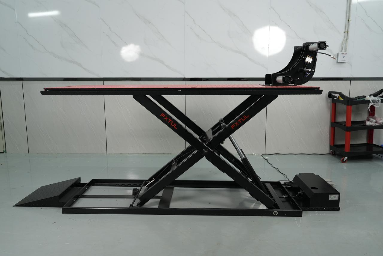
The FXTUL TLM motorcycle lift family includes the TLM350, TLM700 and TLM900 professional service lifts. This guide combines the published TLM variant limits and model-family hardware with a practical trained-operator positioning, restraint, lifting and lowering workflow.
Quick answer: Use the TLM350, TLM700 and TLM900 only after professional commissioning and operator training. Match the installed TLM350, TLM700 or TLM900 data plate to the motorcycle's actual weight, center it and restrain it at approved points, then pause at low height for a stability check. Raise to working height, engage positive mechanical support, clear the full descent path and lower under continuous control.
In this guide
Before you start
A motorcycle lift can cause fatal crushing injuries and an unrestrained motorcycle can overturn. This guide begins after qualified installation, commissioning and handover. It does not cover anchoring, structural or hydraulic repair, safety-device adjustment or improvised descent. The installed data plate, delivered instructions, site inspection program and motorcycle support information control every lift.
- confirm that the installed model belongs to the FXTUL TLM lift family and identify whether it is TLM350, TLM700 or TLM900;
- read the controlling data plate, inspection status and delivered operator instructions;
- identify raise, lower, safety-release and emergency controls plus every visible pinch zone;
- verify motorcycle service weight, center of gravity, ground clearance and approved restraint points;
- plan any center-of-gravity change caused by removing a heavy component; and
- clear the complete loading, lifting and descent zone and assign a spotter when needed.
Keep the manual supplied with the installed TLM variant beside its data plate, inspection record, site operating procedure and the motorcycle’s support information. Delivered records control whenever a web dimension, remembered capacity or nearby variant differs.
TLM350, TLM700 and TLM900 controls and specifications
| Specification or function | Current model |
|---|---|
| TLM350 | 350kg capacity; 185mm minimum height; 1150mm lifting height; 2000 × 600mm platform; 200kg listed machine weight |
| TLM700 | 700kg capacity; 190mm minimum height; 1150mm lifting height; 2200 × 800mm platform; 265kg listed machine weight |
| TLM900 | 900kg capacity; minimum-height web entry has an unresolved unit error; 1150mm lifting height; 2200 × 800mm platform; 310kg listed machine weight |
TLM350, TLM700 and TLM900 are separate capacity variants: the current product page lists 350kg, 700kg and 900kg respectively. Never select a limit from the family name alone. The same page gives an unresolved ‘110 m’ minimum-height entry for TLM900, so the installed data plate and delivered technical record—not that web typo—must control clearance and setup decisions.
How to use the TLM350, TLM700 and TLM900
Step 1: Identify the installed TLM variant and controlling data plate
Confirm whether the commissioned lift is a TLM350, TLM700 or TLM900 and read its installed data plate, manual and inspection record. The current product page lists 350kg, 700kg and 900kg capacities respectively; never apply the TLM900 limit to a TLM350 or TLM700. The web page's TLM900 minimum-height entry contains an unresolved unit typo, so use the delivered technical record for clearance planning.
Before moving on, identify the exact TLM350, TLM700 or TLM900 from its installed data plate, confirm commissioning and inspection status and verify the motorcycle’s actual weight and planned balance are within that variant’s limits.
Step 2: Confirm commissioning, inspection and operator authorization
Use the lift only after qualified installation, commissioning and handover. Confirm its required inspection is current, the platform, X-frame, controls and safety devices match the delivered configuration and the machine is not tagged out. This operator workflow does not cover anchoring, hydraulic repair, structural repair, synchronization adjustment or emergency descent.
Step 3: Clear the lift bay and inspect the complete machine
Remove people, tools, hoses and loose objects from the platform and full movement zone. Inspect the platform, approach area, frame, pivots, fasteners, hoses or cables, control, wheel restraint and positive safety device provided on the installed lift. Keep it out of service for leakage, cracks, deformation, damaged restraints, abnormal looseness or an uncertain control.
Step 4: Confirm motorcycle weight, balance and service plan
Obtain the motorcycle's actual service weight and account for fuel, luggage, accessories and any attachment used during lifting. Plan its center of gravity, wheel position, ground clearance, support and tie-down points from motorcycle and lift information. If a wheel, engine, battery or other heavy assembly will be removed, approve the resulting balance change before the motorcycle enters the platform.
Step 5: Lower and prepare the platform for loading
Place the lift in its approved loading position with the approach clear and the platform stable. Set the installed wheel restraint and tie-down equipment to the delivered procedure without creating a trip or snag point. Do not improvise ramps, blocks or extensions and do not exceed the platform dimensions or configuration documented for the exact TLM variant.
Step 6: Load and center the motorcycle under control
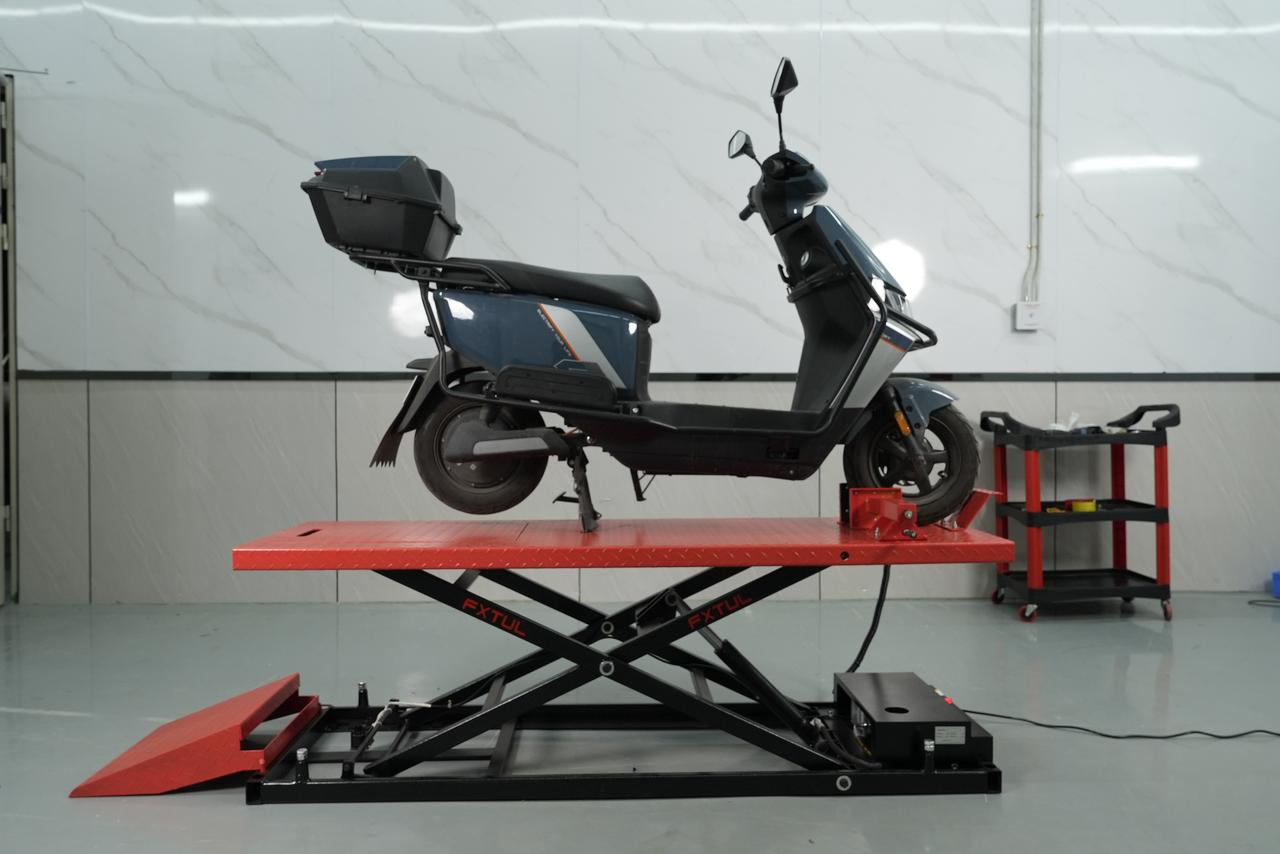
Use the site-approved method and a spotter where visibility or motorcycle mass requires one. Move the motorcycle at walking speed, align it with the platform centerline and stop at the intended wheel position. No one may ride the motorcycle while the platform moves; keep feet and hands away from platform edges, wheel restraints, scissor members and other pinch zones.
Step 7: Stabilize and restrain at approved points
Hold the motorcycle upright with the installed wheel restraint, stand or support arrangement permitted by the lift and motorcycle procedure, then apply rated tie-downs only to approved structural points. Arrange opposing restraint without compressing suspension excessively or loading bodywork, controls, exhaust, wiring or brake lines. Confirm straps and hooks cannot enter the lift mechanism.
Step 8: Raise only enough for an initial stability check
Clear everyone from the movement zone and raise the platform a small distance. Stop, release the control and verify the motorcycle remains centered and upright, every restraint stays seated, the platform and frame travel normally and no strap, stand, wheel or motorcycle part is shifting. Lower and correct the setup if any condition is uncertain.
Step 9: Raise to working height and engage positive support
Continue lifting smoothly while watching the motorcycle, platform and full mechanism. Stop at the required working height and place the lift on the positive mechanical safety position specified for the installed unit. Verify engagement before anyone approaches the work zone; hydraulic or pneumatic pressure alone is not approved support for an elevated motorcycle.
Step 10: Control the lift and motorcycle during service
Protect the controls from unauthorized use and keep the exclusion zone clear. Do not alter a restraint or remove a heavy component without an approved balance plan and added support where required. Stop work for movement, slack restraints, a changing center of gravity, leakage, impact, abnormal sound or uncertain safety engagement.
Step 11: Clear, release, lower and close the job
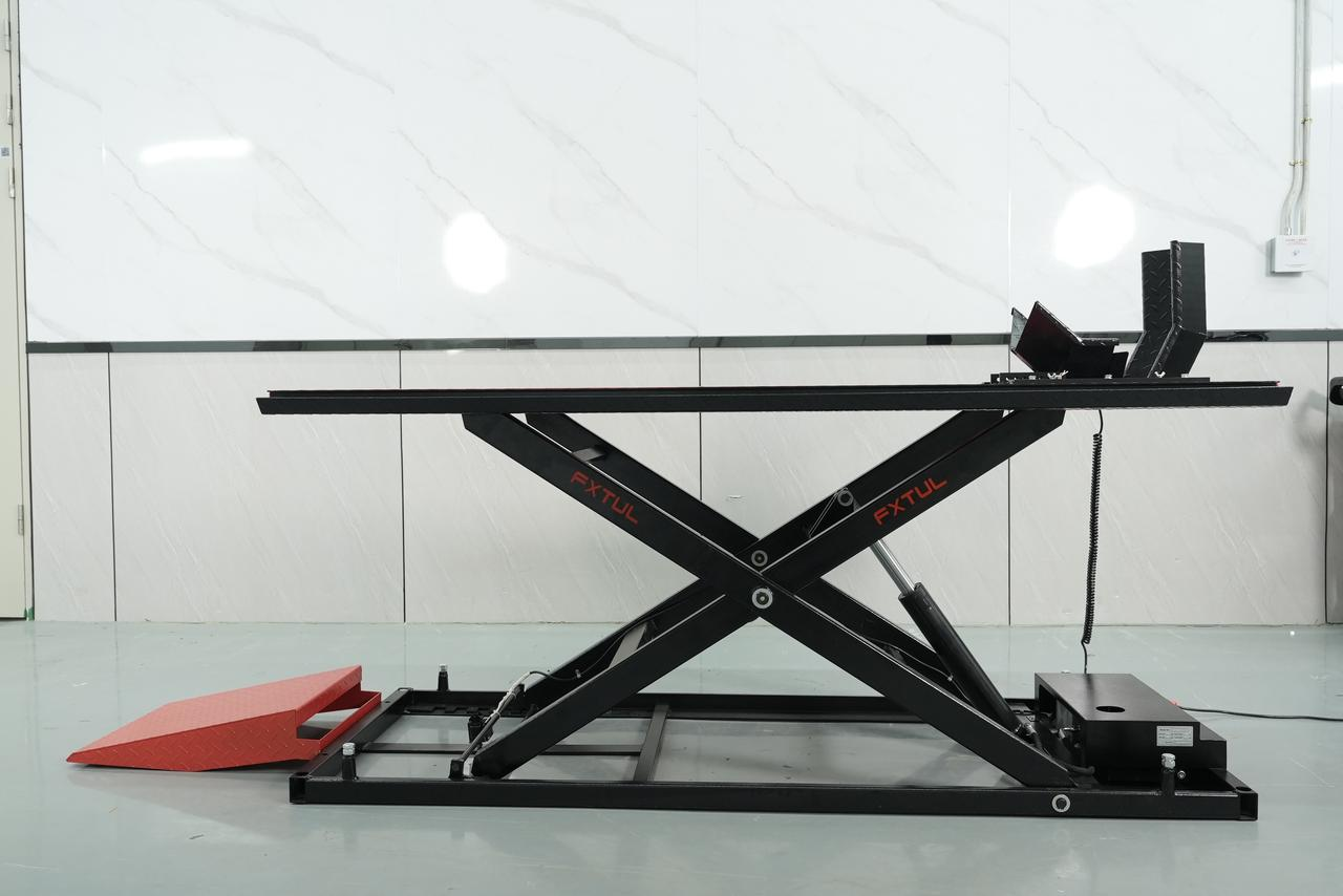
Account for tools and removed parts, restore stable motorcycle balance and clear every person and obstruction from the lift. Raise only as required to unload the safety device, release it by the delivered control and lower smoothly while watching the whole path. At the loading position, stabilize the motorcycle before removing tie-downs, unload under control, park the lift and record any abnormality before the next use.
Before the next motorcycle enters, confirm the platform is in its approved loading position, the bay is clear and every leak, impact, loose restraint, unusual sound or abnormal movement has been recorded.
Read and verify the result
A successful lift is a chain of verified conditions. The motorcycle remains centered and upright, rated restraints stay seated, the platform travels normally, a low-height pause proves the setup and the installed positive safety device supports the working position. During descent, the safety device releases by the intended control and the motorcycle remains stable until normal support is restored.
- Initial lift is the best time to catch a migrating tire, stand, strap or center-of-gravity problem before full height magnifies it.
- Hydraulic or pneumatic pressure may raise a lift; the installed positive mechanical device provides the intended working support.
- Removing a wheel, battery, engine or luggage system can shift balance even when total weight stays below capacity.
- Any leak, crack, uneven travel, unexpected movement or uncertain safety engagement requires isolation and qualified inspection.
Stop and isolate the lift if the motorcycle tilts, a wheel or restraint moves, the platform travels abnormally, a safety device does not engage or release, fluid appears, a hose or cable shifts, the lift makes an abnormal sound or anyone enters the exclusion zone. Do not bypass a safety device, continue under pressure alone or improvise a descent.
Common mistakes and care
- Use the installed data plate and delivered technical record: TLM350, TLM700 and TLM900 do not share one universal capacity.
- The current product page contains an unresolved TLM900 minimum-height unit typo; do not use that web value for clearance or installation decisions.
- Operate only after qualified installation, commissioning, inspection and operator handover; do not improvise anchoring, structural, hydraulic or safety-device work.
- No person may ride the motorcycle or enter the lift movement zone while the platform is moving.
- Complete a low-height stability check and engage the installed positive mechanical safety device before service work.
- Plan for center-of-gravity changes before removing a wheel, engine, battery or other heavy assembly.
- Do not use the TLM900 capacity for TLM350 or TLM700, and do not treat the product-family maximum as the rating of every installed lift.
- Do not ride the motorcycle while the platform moves or rely on one hand, one loose stand or bodywork as restraint.
- Do not attach tie-downs to controls, exhaust parts, wiring, brake lines or unapproved cosmetic structure.
- Do not enter the work zone before the low-height check and positive safety engagement are complete.
- Do not remove a heavy component until the resulting balance and any secondary support have been approved.
Frequently asked questions
Do TLM350, TLM700 and TLM900 have the same lifting capacity?
No. FXTUL lists 350kg, 700kg and 900kg respectively. Use the installed model and data plate, and include the motorcycle, fuel, luggage, accessories and service attachments in the load decision.
Can I work on the motorcycle while the lift is held only by pressure?
No. Complete the low-height stability check and place the commissioned lift on its positive mechanical safety support before service work. Do not bypass or improvise a safety device.
Can I remove an engine or wheel after the motorcycle is already raised?
Only when the changed center of gravity, remaining restraints and any secondary support were planned and approved before removal. Lower and revise the setup if balance becomes uncertain.
Final TLM350, TLM700 and TLM900 checklist
- Exact TLM variant, controlling capacity, commissioning and inspection status confirmed
- Motorcycle weight, balance, support and approved restraint points verified
- Bay clear; motorcycle centered and every rated restraint seated
- Low-height stability check passed with normal lift travel
- Positive mechanical safety support engaged before service work
- Tools accounted for; descent zone clear and safety released by the intended control
- Motorcycle unloaded under control; lift parked and abnormalities recorded
The safest TLM350, TLM700 and TLM900 workflow is deliberately repetitive: identify the exact capacity, verify balance and restraint, pause low, work only on positive support and clear the whole path before descent. Those checks matter more than how quickly the platform reaches working height.











Comments 0
Questions, fixes, and real-world diagnostic notes from readers.
Be the first to share a diagnostic result or ask a follow-up question.