
How to Use the MRCARTOOL L205 Digital HVAC Manifold Gauge Set

The MRCARTOOL L205 digital HVAC manifold gauge set measures low- and high-side gauge pressure simultaneously, derives evaporation and condensation saturation temperatures for the selected refrigerant, displays relative vacuum and records pressure change over time. The correct workflow is not simply “attach and open.” Identify the refrigerant and both service ports, inspect and purge all three hoses, close both manifold valves, zero the sensors without trapped pressure, then open only the flow path required by the vehicle manufacturer’s recovery, evacuation or charging procedure.
Quick answer: Recover any existing refrigerant with approved equipment; never vent it. With both L205 valves closed, connect blue to low side, red to high side and the center hose to the required service equipment. Power on, zero both unpressurized sensors, select pressure, relative-vacuum or leak-test mode, and choose the exact refrigerant and units. For evacuation, open both valves and run the pump, then close both valves before evaluating stability. For charging, use the specified refrigerant and mass, purge air by an approved contained method, keep the high-side path closed during running low-side charging, then close the source and manifold valves before disconnecting.
In this guide
Understand what the L205 measures
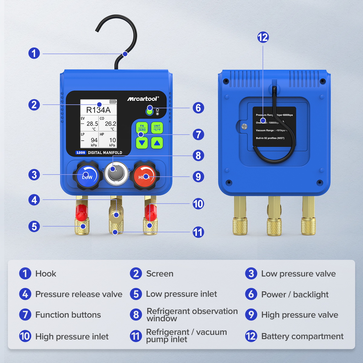
The exact L205 manual specifies simultaneous low- and high-side gauge-pressure measurement, a relative-vacuum mode and a timed pressure-leak mode. It lists 92 refrigerants, a 0–6000 kPa positive-pressure range, -101 to 0 kPa relative-vacuum range, 1 kPa resolution, ±0.5% full scale plus five digits stated pressure accuracy and a 10 MPa overload limit. Available pressure units are kPa, MPa, bar, inHg and psi. Power comes from three AA/LR6 batteries.
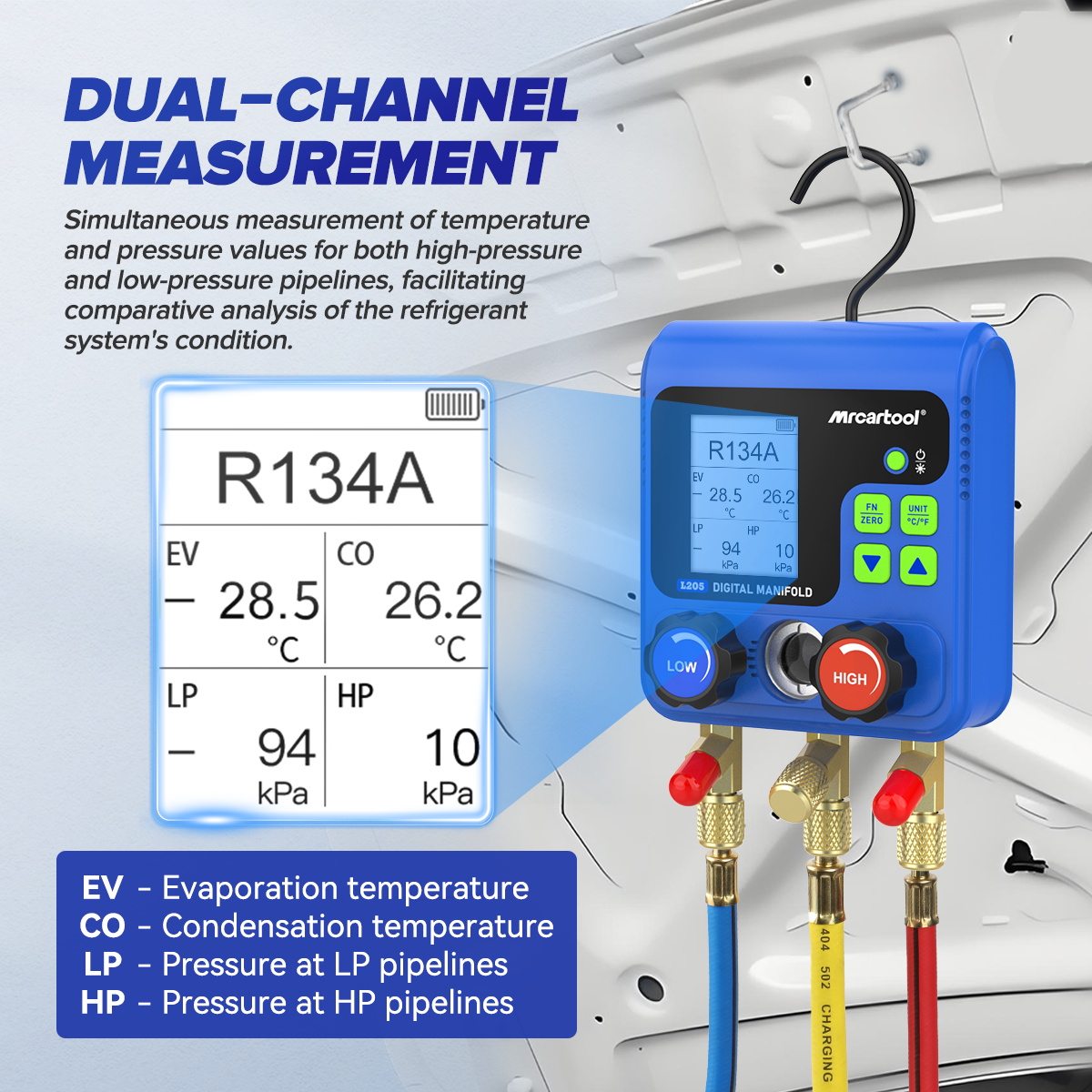
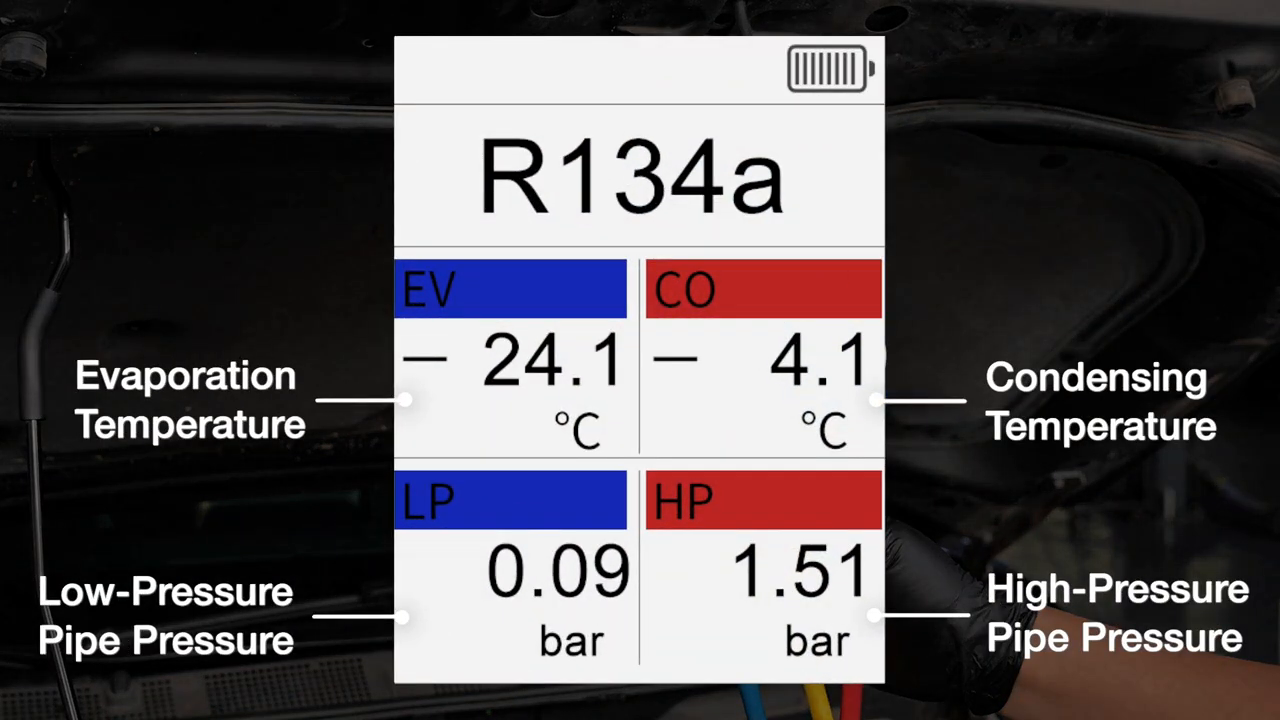
In refrigerant mode, EV and CO are calculated saturation temperatures derived from low- and high-side pressure for the selected refrigerant. They are not vent temperature or actual pipe temperature. Superheat and subcooling still require properly placed temperature probes and the exact system test condition. Simultaneous pressure improves interpretation, but the L205 screen alone cannot distinguish every charge, airflow, restriction, sensor, expansion-device or compressor-control fault.
Refrigerant service can cause frostbite, eye injury, fire, toxic decomposition products and equipment damage. Wear suitable eye and hand protection, work in a ventilated area away from ignition sources, identify the refrigerant before connection, and use only compatible recovery, vacuum and charging equipment. Follow local licensing and refrigerant-handling rules plus the exact vehicle service information.
Do not treat vacuum percentage as a micron reading
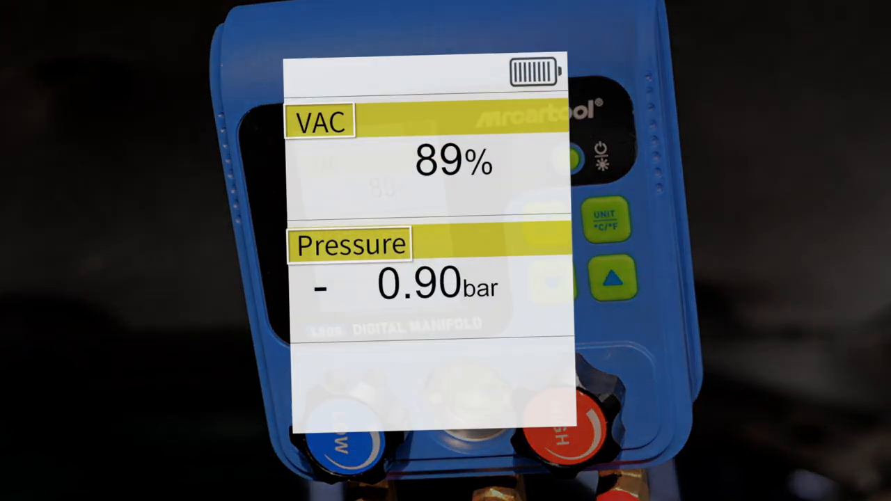
The L205 can display negative pressure and a vacuum percentage, which is useful for watching the evacuation trend. It is not specified as a deep-vacuum micron gauge. A percentage that looks stable does not prove that moisture has boiled out, that the system meets a manufacturer’s micron target or that it will hold after temperature equalization. Where the service procedure requires an absolute vacuum level, connect a calibrated micron gauge at the specified point and use L205 as a manifold control and trend display.
Prepare the vehicle, hoses and gauge
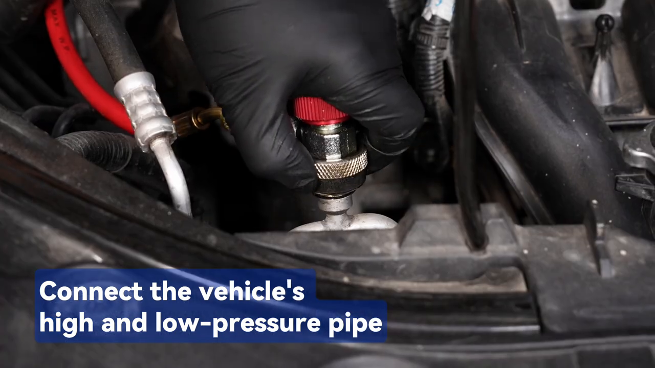
Start with the vehicle label and service information. Confirm the refrigerant designation, specified charge mass, oil requirements, service-port locations and any hybrid or electric-vehicle isolation requirements. If the refrigerant is unknown or contaminated, test it with suitable identification equipment before connecting your normal service set. Recover an existing charge into approved equipment. Do not use a vacuum pump as a recovery machine and do not release refrigerant to atmosphere.
- Inspect the L205 housing, hook, display, brass connections, pressure-release control and both valves for damage or contamination.
- Use hoses, couplers, cylinder and recovery equipment rated for the refrigerant and maximum possible pressure.
- Confirm every hose is internally clean and that seals and Schrader depressors are intact; replace damaged parts before service.
- Keep both L205 valves closed while arranging hoses, and keep unused connections capped so dirt and moisture cannot enter.
- Suspend the gauge securely from its hook where it cannot contact belts, fans, exhaust parts or high-voltage components.
- Record ambient temperature and the starting condition; pressure changes with temperature even when no refrigerant leaks.
Select the working mode, refrigerant and units
Long-press the power key to turn the L205 on or off; a short press controls the backlight. Short-press the mode/zero key to move among refrigerant filling and pressure inspection, vacuum and pressure-leak screens. Long-press that key to zero both pressure readings only when the gauge is not exposed to trapped system pressure. The unit key changes pressure units with a short press and °C/°F with a long press. In refrigerant mode, use the refrigerant key to choose the database entry; in leak mode the same key starts and stops recording.
Choose the exact refrigerant shown on the vehicle label—not the refrigerant with the closest pressure. The manual lists 92 entries, including R134a, R1234yf and R744, but explicitly excludes R717 and other ammonia refrigerants; it also limits R744 testing to 50 bar. Database presence does not make every hose, coupler or recovery machine chemically and pressure compatible. Never leave evacuation, pressure hold or charging unattended.
Zero at the correct time
The manual instructs a long press of the mode/zero key when startup digits do not return to zero. Do not use zero to hide real residual pressure. Close and isolate all hoses, bring both sensor paths to the proper zero reference, confirm neither side contains trapped pressure, then zero. If either reading remains implausible, stop, inspect the valve and hose arrangement and compare the gauge with a known reference.
Evacuate the A/C circuit step by step
1. Build a sealed evacuation path
With the vehicle off and the refrigerant already recovered, connect the appropriate vehicle service coupler to the L205 inlet path shown for your configuration. Connect the vacuum-pump hose to the corresponding outlet. Hand-tighten flare connections using the sealing method specified for the fitting; overtightening can damage seats and undertightening pulls room air into the circuit. Route hoses so a closing hood, fan or hot component cannot trap them.
2. Select vacuum mode and start flow
Power on, select vacuum mode and verify the unit. With the recovered vehicle connected blue-to-low and red-to-high and the center hose connected to the pump, open both L205 valves and start the vacuum pump. Watch both readings trend toward vacuum. If one side does not respond, stop and check the coupler, valve and restriction on that branch rather than continuing with an unverified flow path.
3. Evacuate for the specified condition
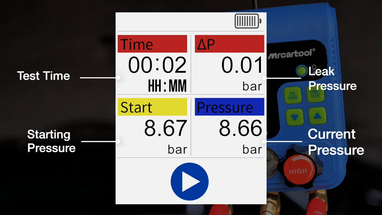
Continue evacuation for the time and absolute vacuum specified by the vehicle or equipment manufacturer. The manual notes that its test cylinder may show roughly 97–98% after several minutes, but that example is not a universal automotive endpoint. System volume, ambient temperature, hose diameter, pump capacity, recovered oil and retained moisture all change the time required. If a micron target is specified, use the micron gauge to decide when dehydration is complete.
4. Isolate before evaluating stability
Close both L205 valves to isolate the serviced circuit before switching off or isolating the pump in the order required by the equipment manufacturer. Start the timed pressure-leak display and observe the specified hold period. A changing value can result from a leak, outgassing, remaining moisture, hose permeation or temperature change. Repeat the setup and use an approved leak-location method before condemning a component. Delta pressure indicates change over time; it does not show where the leak is.
Charge only by the vehicle specification
Charging is a separate controlled procedure. Connect the correct refrigerant source through compatible charging or recovery equipment and place a calibrated scale under the cylinder when the service procedure specifies charge by mass. Purge non-condensable air from the charging hose using an approved method that contains refrigerant. Do not guess charge quantity from the L205 saturation display, and never mix refrigerants or oils.
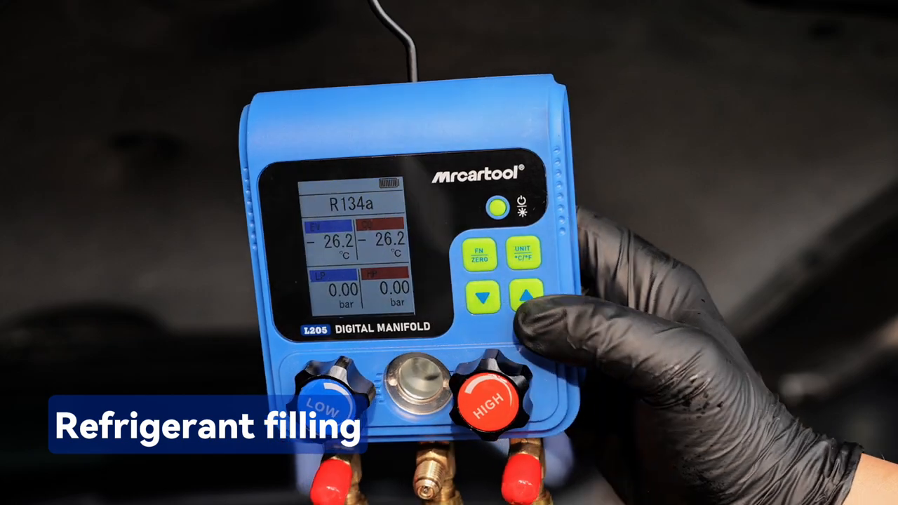
If the vehicle procedure calls for charging through the low side with the system operating, keep the high side isolated and follow the manufacturer’s state-of-refrigerant and flow instructions. Prevent liquid slugging into the compressor. Keep hands and hoses away from moving parts and monitor cylinder mass, pressure, actual line temperatures and outlet performance. Stop at the specified charge—not when a pressure merely looks familiar. Overcharge, undercharge, airflow faults and compressor-control faults can produce overlapping symptoms.
Read the display without overdiagnosing
The large value is measured pressure; the refrigerant identifier and calculated saturation temperature provide context. Compare the reading only after the system has stabilized in the exact test condition defined by the vehicle procedure: ambient temperature, doors or windows, blower setting, engine speed, recirculation, condenser airflow and compressor command all matter. A single low-side reading cannot distinguish every restriction, low-charge, airflow, sensor or compressor problem.
Close, disconnect and store
When the specified charge or test is complete, close the refrigerant source first so uncontrolled flow stops, then close both L205 valves and isolate the vehicle service couplers in the sequence required by the service equipment. Allow trapped hose pressure to be recovered or transferred using an approved method; do not crack a fitting to bleed refrigerant. Disconnect carefully, install both service-port caps and leak-check the ports when required.
Turn off the L205, wipe the case with a slightly alkaline cleaner or soapy water as the manual permits, and keep liquid out of the electronics and pressure path. Cap all fittings. Inspect hoses for oil saturation, cuts, swelling and damaged seals; clean or replace contaminated lines. Store the gauge protected from impact. Pressure instruments require periodic accuracy checks, especially after a drop, overload or reading discrepancy.
Troubleshooting
| Symptom | Check first |
|---|---|
| One pressure side does not respond | Correct service port, coupler engagement, closed valve, blocked hose and damaged depressor |
| Relative vacuum does not deepen | Recovered system, pump condition, both flow paths, hose seals, couplers and gross leaks |
| Pressure changes during an isolated hold | Temperature change, hose or connection leakage, outgassing, moisture and system leakage |
| EV or CO looks wrong | Selected refrigerant and units; these are pressure-derived saturation temperatures |
| LP or HP differs from another gauge | Both zero conditions, units, hose sides, stabilization and calibration status |
| Low-battery icon appears | Replace all three AA/LR6 batteries as a matched set before relying on the reading |
| A valve is difficult to turn | Isolate pressure and inspect the valve; do not force it or use it as a regulator |
Frequently asked questions
Can L205 read high and low pressure at the same time?
Yes. The exact L205 manual describes simultaneous double-pressure measurement and the official video shows LP and HP together. Close both manifold valves for static pressure measurement; opening a valve changes the flow path and must be intentional.
Does a stable vacuum percentage prove the system is leak-free?
No. It is a useful trend, but it is not a location test or a specified micron measurement. Temperature, moisture and hose condition affect the result. Follow the manufacturer’s hold criteria and confirm with the appropriate absolute-vacuum and leak-detection equipment.
Can I choose refrigerant from the pressure reading?
No. Many refrigerants have overlapping pressure ranges. Identify the refrigerant from reliable vehicle records and, when uncertain, use a refrigerant identifier before connecting service equipment.
Can I charge until the pressure looks normal?
No. Charge the specified refrigerant by the documented mass and method. Pressure is a verification input affected by ambient conditions, airflow and system control; it is not a substitute for charge quantity.
Final L205 checklist
- Refrigerant identity, charge specification and both service ports verified
- Existing refrigerant recovered with approved equipment; nothing vented
- Blue, red and center hoses clean, compatible, pressure-rated and correctly routed
- Both L205 valves closed before connection, sensor zero and mode selection
- Correct refrigerant, mode, pressure unit and temperature unit selected
- Simultaneous LP and HP interpreted only under the specified operating condition
- Evacuation judged by the manufacturer’s time and absolute-vacuum criteria
- Pressure hold interpreted with temperature, hose and outgassing effects considered
- Charge metered by specified mass with the high-side flow path controlled
- Source and manifold valves closed before controlled hose isolation
If the supplied connections, display labels or operating sequence differ from the version shown here, select the exact L205 PDF on the MRCARTOOL manual download page before service.
The L205 is most useful when every number is tied to a known condition. Confirm the refrigerant, zero both sensors without trapped pressure, connect blue and red to the correct sides, use the center port deliberately, and interpret EV and CO as derived saturation temperatures. Use relative vacuum and delta pressure as trends, charge by the vehicle specification and contain the hose charge at disconnection. Those habits turn its dual display into reliable service evidence without asking it to identify refrigerant, measure deep vacuum or diagnose the whole A/C system by itself.











Comments 0
Questions, fixes, and real-world diagnostic notes from readers.
Be the first to share a diagnostic result or ask a follow-up question.