
How to Use the AUTOOL ATL-4SM/ATL-3SM Mobile Scissor Lift

The AUTOOL ATL-4SM/ATL-3SM is a professional mobile low-rise scissor lift. This guide turns the current model-specific controls and official operating sequence into a practical start-to-finish workflow.
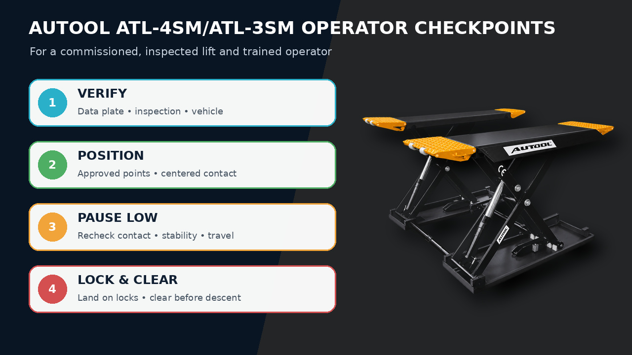
Quick answer: Use the ATL-4SM/ATL-3SM only after professional commissioning and operator training. Verify the data plate and inspection status, position the eligible vehicle on its approved lifting points, pause at initial contact, complete a low-height stability check, raise to working height and land on matching mechanical locks. Clear the entire bay before a controlled synchronized descent.
In this guide
Before you start
A vehicle lift can cause fatal crushing injuries if it is installed, maintained or operated incorrectly. This operating guide starts after qualified installation, commissioning and handover. It does not cover anchoring, wiring, hydraulic work, synchronization adjustment, lock repair or improvised emergency descent. Follow the lift owner’s inspection program, the delivered instructions and the exact vehicle lifting-point data.
- confirm the installed model and configuration read AUTOOL ATL-4SM/ATL-3SM, and read the controlling rated data plate;
- confirm the lift is commissioned, within its required inspection period and not tagged out;
- identify raise, lower, lock-release and emergency controls plus every visible pinch zone;
- verify actual vehicle weight, balance, ground clearance and manufacturer-approved lifting points;
- clear the bay of people, tools, hoses and overhead or floor obstructions; and
- arrange a spotter when the operator cannot see the vehicle, platforms or descent path completely.
Use the AUTOOL manual download center to locate the current instructions when a manual is available. The delivered model label and current vehicle service information control if an older image or remembered setting differs.
ATL-4SM/ATL-3SM controls and specifications
The delivered data plate, commissioning record and site procedure control the usable capacity and configuration. Do not combine an optional arm, ramp, pad, power supply or lock-release feature with the standard model unless the installed equipment documents it. The ATL-4D web materials contain a 4000/4500 kg conflict, so its controlling rating must be verified on the installed unit before use.
How to use the ATL-4SM/ATL-3SM
Step 1: Accept only a commissioned lift and authorized operating area
Treat the ATL-4SM/ATL-3SM as installed workshop machinery, not a portable hand tool. A qualified installer must commission the mobile low-rise scissor lift, and the owner must provide its current inspection record, rated data plate, operating controls, emergency procedure and operator training before routine use. Do not use this guide to install, anchor, wire, bleed, synchronize or repair the lift.
Before moving on, confirm the lift is commissioned, in inspection, correctly identified and controlled by the delivered data plate; installation or repair uncertainty requires qualified service, not operator experimentation.
Step 2: Identify the exact model, controls and lock behavior
Read the ATL-4SM/ATL-3SM data plate and delivered control labels. Locate raise, lower, lock-release and emergency-stop controls; identify every mechanical lock, arm restraint, platform, ramp and pinch zone visible to the operator. Test the unloaded operating and lock sequence only if the site procedure authorizes it. First confirm whether the installed unit is ATL-4SM or ATL-3SM and whether pneumatic or optional electric unlocking is fitted; those differences change the operating boundary.
Step 3: Inspect the bay and lift before bringing in a vehicle
Keep people, tools, hoses and loose parts out of the bay. Check for fresh hydraulic leakage, damaged pads or platforms, loose or missing restraints, unusual cable or hose position, damaged guards, uneven resting height or an out-of-service tag. If any condition is abnormal, isolate the lift and arrange qualified inspection.
Step 4: Confirm the vehicle is eligible for this exact lift
Verify actual vehicle weight, weight distribution, wheelbase, ground clearance and the vehicle maker’s lifting points against the commissioned lift configuration and its data plate. Include cargo, accessories and fluid load. Never use an advertised maximum as permission to lift an unknown or marginal vehicle.
Step 5: Position the vehicle and establish all contact points
Use a spotter where visibility is limited and stop the engine once the vehicle is centered in the approved direction. Apply the site’s transmission, parking-brake and wheel-restraint procedure. Drive squarely onto the platforms or position the lift only as the delivered operating instructions permit. Center the vehicle’s mass, confirm tire or approved lifting-point contact, and secure ramps or extensions in their operating position. Never contact fuel, battery, exhaust, suspension or body areas unless the vehicle maker explicitly identifies them as lifting points.
Step 6: Raise only to initial contact and recheck every point
Operate the raise control in short increments until all pads, arms or platforms make firm contact. Stop before the tires leave their supporting surface. Walk around without entering a pinch zone and confirm every contact remains centered, every arm restraint is engaged where fitted, and no vehicle part is deforming or shifting.
Step 7: Perform the low-height stability check
Raise the vehicle only a small distance, stop, and verify it is level and stable using the facility’s approved stability check. Watch both sides for equal movement and listen for abnormal mechanical or hydraulic noise. Lower and reposition if any pad migrates, an arm moves, the vehicle rocks excessively or the lift travels unevenly.
Step 8: Raise to work height and land on mechanical locks
Continue raising while maintaining a clear exclusion zone. Stop at the required height, then use the delivered control sequence to lower the lift gently onto matching mechanical locks. Confirm the lift is supported by the locks—not held only by hydraulic pressure—before anyone enters beneath the vehicle.
Step 9: Control the work while the vehicle is elevated
Keep the controls protected from unauthorized operation and maintain a clear path around the vehicle. Do not remove a heavy component, apply major force or change vehicle weight distribution unless the approved lift and vehicle procedure accounts for it. Stop work for drift, leakage, impact, unusual noise or loss of lock engagement.
Step 10: Clear the bay and lower with synchronized release
Remove tools, stands and personnel, close doors and verify the full descent path. Raise slightly to unload the locks, apply the exact pneumatic or configured release control, confirm every lock releases together, and lower while watching both platforms. Stop immediately if one side remains locked, the vehicle shifts, an obstruction enters the bay or motion is not smooth; never bypass a lock or improvise an emergency descent.
Step 11: Finish at the lowest position and record abnormalities
Lower fully to the approved parked position, remove restraints only when the vehicle is supported normally, return arms, platforms and ramps to their stored state, and drive out with a spotter if needed. Clean the bay and record any leak, impact, unusual sound, uneven motion or control issue before the next vehicle uses the lift.
Before the next vehicle enters, confirm the lift is fully parked, arms or platforms are stored, the bay is clear and every leak, impact, unusual sound or uneven movement has been reported.
Read and verify the result
A successful lift is a sequence of verified conditions, not simply upward motion. All contact points must remain centered, both sides must travel evenly, the vehicle must pass the facility’s low-height stability check, and matching mechanical locks must carry the elevated load. During descent, every lock must release together and the vehicle must remain stable until it returns to normal support.
- Initial contact is the last easy opportunity to correct a misplaced pad, arm, platform or ramp before the full load transfers.
- A low-height pause exposes unstable balance or migrating contact while the consequence and recovery distance are still limited.
- Hydraulic pressure raises the lift; engaged mechanical locks provide the intended working support on equipped ATL models.
- Any uneven travel, leak, impact, abnormal sound or uncertain lock behavior requires removal from service and qualified inspection.
Stop and isolate the lift if a contact point moves, the vehicle tilts or rocks excessively, the sides travel unevenly, a lock does not engage or release, hydraulic fluid appears, a hose or cable is displaced, the lift makes an abnormal sound, or any person or obstruction enters the exclusion zone. Do not bypass a lock, continue under hydraulic pressure alone or improvise a descent.
Common mistakes and care
- Operation is limited to trained, authorized personnel using a professionally installed and currently inspected lift.
- Never exceed the delivered data-plate rating or guess vehicle lifting points from appearance.
- Keep every person outside the lift and vehicle pinch zones during raising and lowering.
- Land the lift on matching mechanical locks before anyone works beneath the vehicle.
- Never bypass a safety lock, modify a control or improvise installation, repair or emergency descent.
- Remove the lift from service for leakage, impact, uneven movement, abnormal noise, damaged contact parts or missing inspection status.
- Do not lift from visually convenient body, battery, fuel, exhaust or suspension parts unless the vehicle maker identifies them as lifting points.
- Do not enter beneath the vehicle before the low-height check and positive engagement on matching mechanical locks.
- Do not remove a powertrain, battery or other heavy component without an approved plan for the resulting center-of-gravity change.
- Do not let an untrained person operate controls, ride in the vehicle or stand in the lift path.
- Keep the lift out of service until a qualified person resolves any abnormality recorded after operation.
Frequently asked questions
Can I install or repair the ATL-4SM/ATL-3SM using this guide?
No. Installation, anchoring, electrical and hydraulic work, synchronization, inspection and repair require the delivered technical instructions plus qualified personnel. This page covers routine trained-operator workflow after commissioning.
When is it safe to work below the vehicle?
Only after correct lifting-point contact, a successful low-height stability check and positive support on matching mechanical locks under the site procedure. Hydraulic pressure alone is not the working support.
What if one side does not release during lowering?
Stop. Keep the area clear and use the site emergency procedure or qualified lift service. Never bypass the remaining lock or improvise a release or descent.
Final ATL-4SM/ATL-3SM checklist
- Commissioning, inspection status, data plate and operator authorization confirmed
- Vehicle weight, balance and approved lifting points verified
- All contacts centered and arm, ramp or platform restraints secure
- Low-height stability and equal travel confirmed
- Lift landed on matching mechanical locks before under-vehicle work
- Bay fully clear; locks released together during controlled descent
- Lift parked, bay cleared and every abnormality recorded
The safest way to use the ATL-4SM/ATL-3SM is deliberately: verify the installed machine and vehicle first, pause twice before committing to full height, work only on positive mechanical support, and treat any unexpected movement or sound as a reason to stop—not something to work around.











Comments 0
Questions, fixes, and real-world diagnostic notes from readers.
Be the first to share a diagnostic result or ask a follow-up question.