
Pierce Aerial Ladder Kept Moving After the Joystick Returned to Neutral: The Command Was Late

Joystick Neutral, Ladder Still Moving? Time The Command
A Pierce aerial ladder sometimes continued raising or lowering for as long as three seconds after the joystick returned to neutral. On an ordinary machine that would be serious; on fire apparatus carrying people above the ground, it is a stop-work fault. The diagnosis had to distinguish what the operator asked for, what the electronics commanded and what the hydraulics did.
A meter or scope capable of displaying an identified joystick voltage and PWM command can support the first two layers of that timeline. The AUTOOL DM303 is one accessible example for bounded low-voltage checks after Pierce information defines the circuit. DM303 can display an identified low-voltage joystick or PWM signal within its ratings. It cannot certify aerial-apparatus safety, monitor every interlock, replace the OEM load chart or prove downstream hydraulic behavior without synchronized channels and qualified procedures.
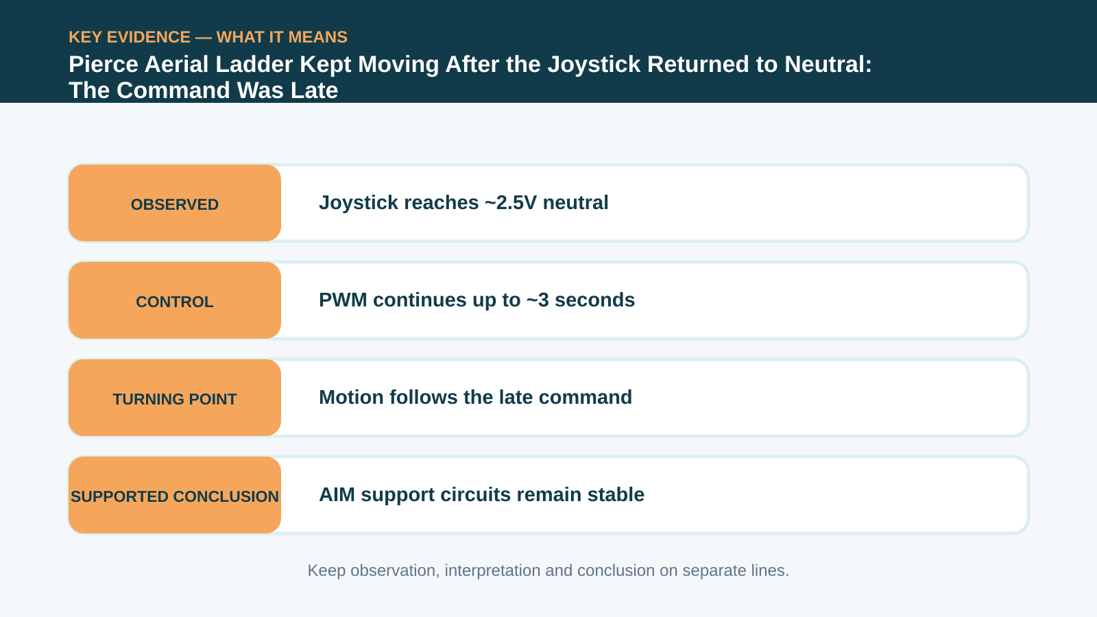
The joystick reached its neutral value of about 2.5 volts promptly, but the aerial interface module continued sending a PWM output for up to three seconds. Module powers and grounds remained sound. Replacing the AIM module removed the delay, and the apparatus operated for a year without recurrence. The hydraulics moved late because the electronic command ended late.
Quick answer: The joystick reached its 2.5V neutral value, but the AIM module continued PWM output for up to three seconds. Module replacement ended the unsafe late motion.
In this guide
- Treat continued ladder motion as a stop-work fault
- Separate joystick input from hydraulic response
- Capture the neutral transition and PWM together
- Measure the delay instead of describing it
- Check module powers, grounds and interlocks
- Follow the signal through downstream converters
- Replace the module under apparatus procedure
- Verify every direction and document the service interval
Treat continued ladder motion as a stop-work fault
Remove the apparatus from emergency service and establish the manufacturer’s support, stabilization and lockout conditions. Record which station, direction and operating mode produces the overrun, whether the ladder is loaded and how weather or temperature affects it. Do not reproduce unexpected movement with anyone in the platform or near pinch and fall zones. A qualified emergency-vehicle technician should control the test, with a spotter and an immediate stop plan. A warning that disappears after a key cycle does not make continued aerial motion acceptable.
Separate joystick input from hydraulic response
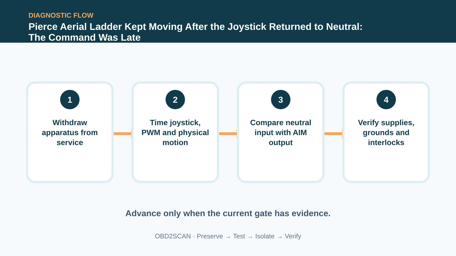
Write the event as three timestamps. First is joystick neutral: when the human request ends. Second is electronic command zero: when the module stops asking a hydraulic converter or valve to move. Third is physical stop: when the structure actually ceases motion. If input is late, investigate the joystick and linkage. If command is late with a timely input, the module layer becomes central. If both electrical signals end correctly but motion continues, the hydraulic valve and mechanical response need attention.
Capture the neutral transition and PWM together
Capture joystick voltage and the relevant pulse-width-modulated output in the same window. The joystick in this case returned to approximately 2.5 volts at neutral. Use manufacturer data for the actual neutral band; do not assume every bidirectional joystick shares that value. Repeat raise and lower commands gently and note whether direction affects the delay. A clean input transition is stronger evidence than an operator’s hand position alone because it shows what the module actually received.
Measure the delay instead of describing it
The AIM module’s output did not fall to zero with the input. It remained active for up to about three seconds, matching the unwanted motion. Measure delay from the same reference point on each capture and retain several events, including passes without the fault. A PWM trace must be interpreted with correct voltage range, time base and grounding. The useful result is not merely that pulses exist; it is that commanded duty continues after the input has already entered its documented neutral state.
Check module powers, grounds and interlocks
Test module battery feed, ignition feed, ground voltage drop and any required enable or interlock while the delay occurs. A power interruption can make a controller behave unpredictably, and a ground problem can corrupt thresholds. Check connectors and terminal grip under vibration rather than relying only on key-off resistance. In the documented case, powers and grounds passed, allowing the input/output mismatch to carry more weight. Still confirm that no external command line or multiplex message asks the module to continue.
| Timeline layer | Expected at joystick neutral | Observed fault |
|---|---|---|
| Operator input | Neutral voltage reached | About 2.5V promptly |
| AIM output | PWM ends without harmful delay | Continued up to ~3 seconds |
| Aerial motion | Decelerates and stops as designed | Continued with late command |
| Module support | Stable power and ground | Passed checks |
Follow the signal through downstream converters
Once the input, supplies and downstream path have been separated, replace the AIM only under Pierce procedure. Confirm hardware and software identifiers, preserve apparatus configuration and use a stable programming supply if commissioning is required. Safety modules and interlocks are not places for experimental bypasses. Inspect related connectors for water entry or pin spread before connecting the replacement so a new controller does not inherit the same external fault.
Replace the module under apparatus procedure
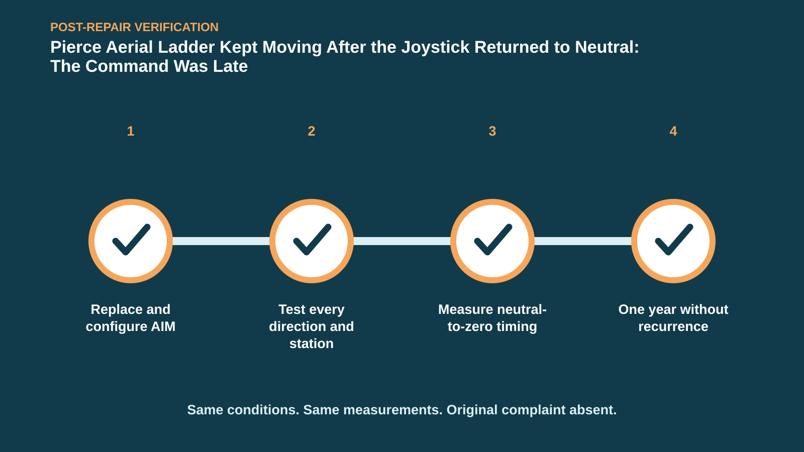
Verification must cover every affected direction and control station under a controlled, unloaded procedure before any operational load test. Measure joystick-to-PWM delay again, confirm normal deceleration and challenge interlocks and emergency stops according to the apparatus checklist. Repeat enough cycles to make the original intermittent behavior likely to appear. Document platform position, hydraulic temperature and each pass. The immediate test succeeded; more importantly, the vehicle remained free of the fault for a documented year.
Verify every direction and document the service interval
Close the repair with an apparatus-specific return-to-service sign-off, not a generic road-test note. Save the before/after timing images and make the crew aware of the exact symptom that requires withdrawal from service. This single Pierce case does not mean every overrun is an interface module; sticky valves, command devices and wiring remain possible. The transferable method is to time the three layers rather than letting continued movement blame whichever component is physically closest.
The ladder was not coasting after a correct stop command—it was still being told to move. Putting operator input and module output on the same clock exposed the delay and gave the safety repair a measurable finish line.









Comments 0
Questions, fixes, and real-world diagnostic notes from readers.
Be the first to share a diagnostic result or ask a follow-up question.