
How to Use the MRCARTOOL T100 Automotive Smoke Leak Detector

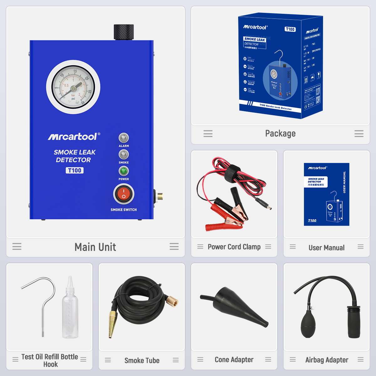
The MRCARTOOL T100 automotive smoke leak detector uses a built-in air pump, pressure gauge and 12-volt supply to check a sealed vehicle circuit before smoke helps pinpoint an opening. The useful result is not simply “smoke appeared.” It is a repeatable leak location found after the temporary test connection, caps and adapters have also been proved tight.
Quick answer: Work with the engine and ignition off in a ventilated, fire-safe area. Inspect the T100, add only 10–20 ml of approved smoke-test oil, hang the unit upright, connect its hose, then attach red to battery positive and black to negative. Use the built-in air stage and gauge to check the sealed setup first. Once stable, switch on smoke, wait about 10 seconds for dense output, connect to the prepared circuit and inspect every joint with a bright light. Stop before opening the system.
In this guide
Confirm the T100 limits before a test
The manual specifies DC 12 V, less than 10 psi rated output pressure, less than 5 L/min rated output flow, 50 W rated power and a 10–20 ml oil-fill range. It also identifies a pressure gauge, liquid-level gauge, protection indicator, smoke indicator and smoke-mode switch. The T100 has no user flow knob or adjustable-pressure control, so do not treat the gauge as permission to tune or increase pressure.
A smoke machine can reveal openings in intake plumbing and other compatible sealed circuits, but it does not decide which circuit may safely be pressurized. Check the exact vehicle procedure first—especially for EVAP components, turbocharger plumbing, crankcases, brake boosters, fuel-related vapor circuits or delicate sensors. Isolate components that the procedure excludes and never introduce smoke into a hot, running or energized engine.
- Use eye protection and gloves; keep the work area ventilated and free from flame, sparks, smoking and hot exhaust parts.
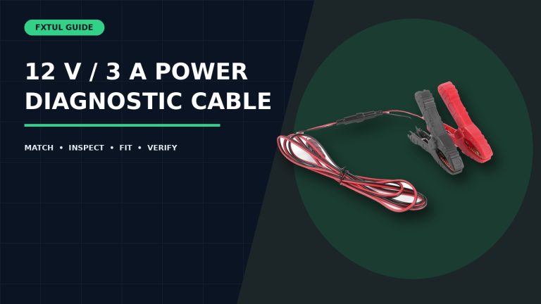
- Use only a sound 12 V vehicle battery and intact power clips; red is positive and black is negative.
- Inspect the case, hook, cap, oil window, outlet, hose, gauge, cord, cone, bladder and plugs before adding oil.
- Select only approved smoke-test oil compatible with this unit; do not substitute a flammable solvent, fuel or aggressive cleaner.
- Know the test boundary, close intended openings and leave pressure-sensitive components connected only when the vehicle procedure permits.
Engine off: The T100 manual requires automotive pipeline leak testing with the engine switched off. Stop for fuel odor, exposed fuel, arcing, a hot surface, damaged wiring, unexpected pressure or smoke entering an electrical enclosure or cabin.
Step 1: Inspect, identify and hang the T100 upright
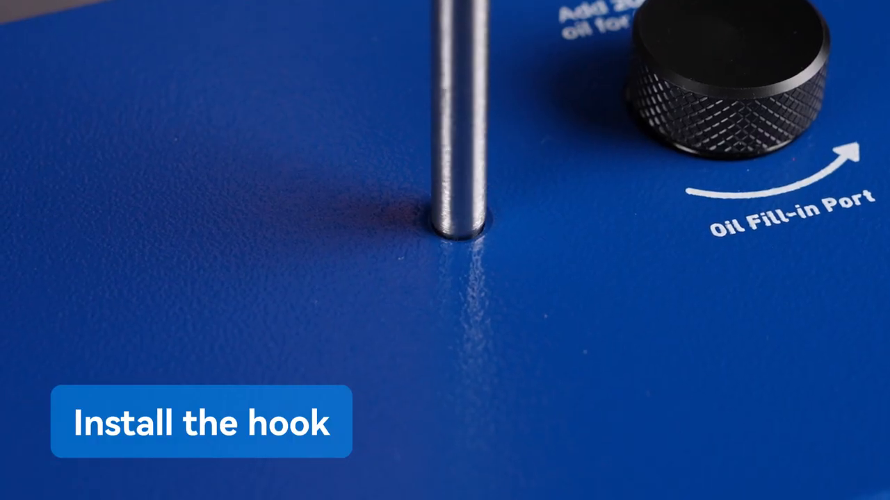
Start with an empty, cool T100 on a stable bench. Verify the model label, 12 V marking and oil level. Install the metal hook fully into the top hook port, then hang the machine securely under the hood where it remains upright and clear of the engine, belts, fans, exhaust, paintwork and battery terminals. Confirm the hood cannot close or move onto the hook.
Step 2: Add 10–20 ml of approved test oil
Open the fill cap only while the machine is cool and disconnected. Use the marked bottle to measure approved test oil. The manual’s preparation sequence starts with 10 ml and its technical range is 10–20 ml; begin at the low end unless the delivered instructions and visible level require more. Pour slowly into the oil-fill port, watch the liquid-level gauge and refit the cap. Overfilling can weaken smoke output and contaminate the hose.
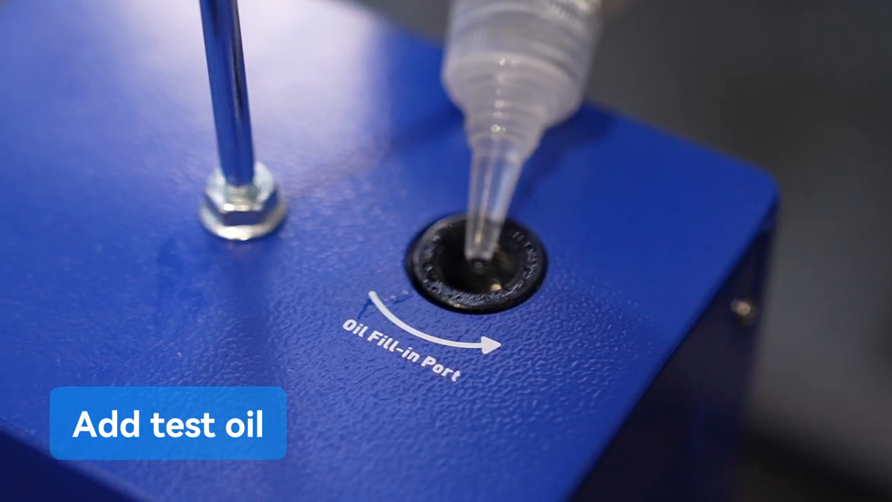
The manual describes turning the disconnected unit upside down to remove an overfill. Avoid creating the problem: measure first, keep the exterior dry and never invert a hot or powered machine. If the oil type, level or contamination is uncertain, stop and use current product support rather than experimenting.
Step 3: Prepare and seal the target circuit
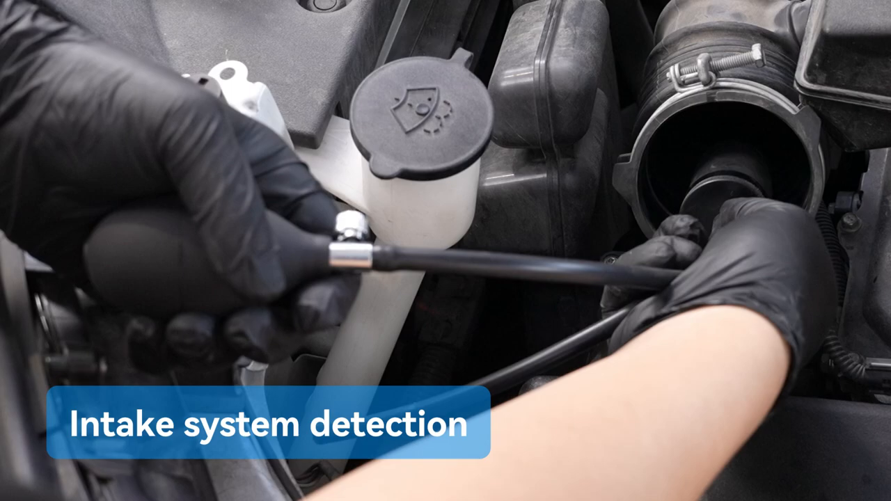
Turn the engine and ignition fully off. Let hot components cool. Identify the section to test from a wiring diagram, service manual or known airflow path. For an intake test, remove the air inlet at the approved location, clean the inside sealing surface and install the supplied cone or compatible adapter. Cap every intentional opening within the selected boundary; a loose cap becomes a false vehicle leak.
Do not automatically remove a throttle body because the official video shows an intake example. Some vehicles require a different access point or component isolation. The correct boundary is the smallest safe section that answers the diagnostic question without exposing a component to a pressure or medium it was not designed to receive.
Step 4: Connect the smoke hose and 12 V power
Push the smoke hose onto the T100 smoke outlet and verify it cannot pull free. Connect the power lead to the T100 before approaching the battery. Keep both clips separated, attach red to positive, then black to negative. The built-in air pump begins when the unit is powered, so be prepared for air at the hose and keep its cone out of dirt.
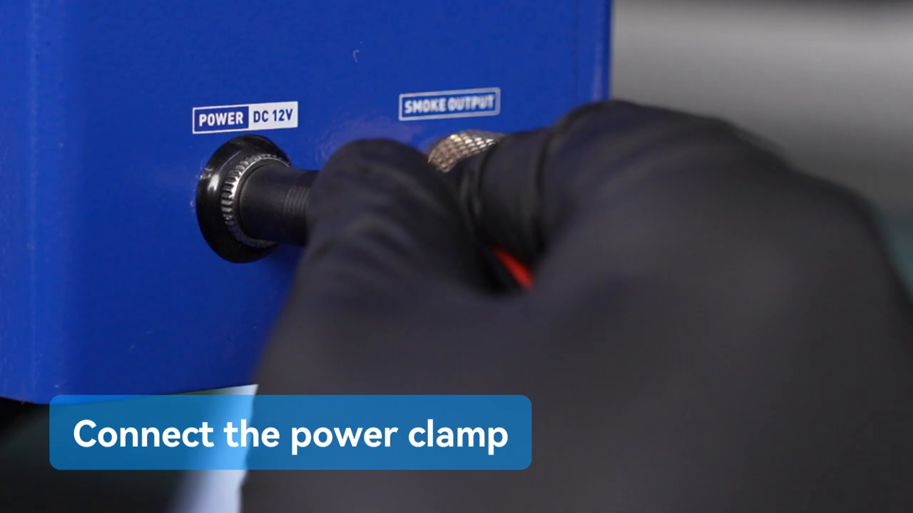
Use the air-only output as a setup check before generating smoke. Hold or seal the outlet briefly only by the delivered self-test method and observe whether the gauge responds. Then connect the cone to the prepared adapter and watch the gauge. A connection that will not build or retain pressure may be open at the test cone, cap, hose or target circuit; correct temporary connections before attributing the result to the vehicle.
Step 5: Switch on smoke and verify output
Press the smoke-mode switch. The smoke indicator should illuminate and the unit should begin heating. The official video shows dense smoke after roughly 10 seconds, but oil temperature, ambient conditions and fill level can change that time. Keep the outlet visible and wait for consistent smoke rather than connecting weak initial vapor and extending the test unnecessarily.
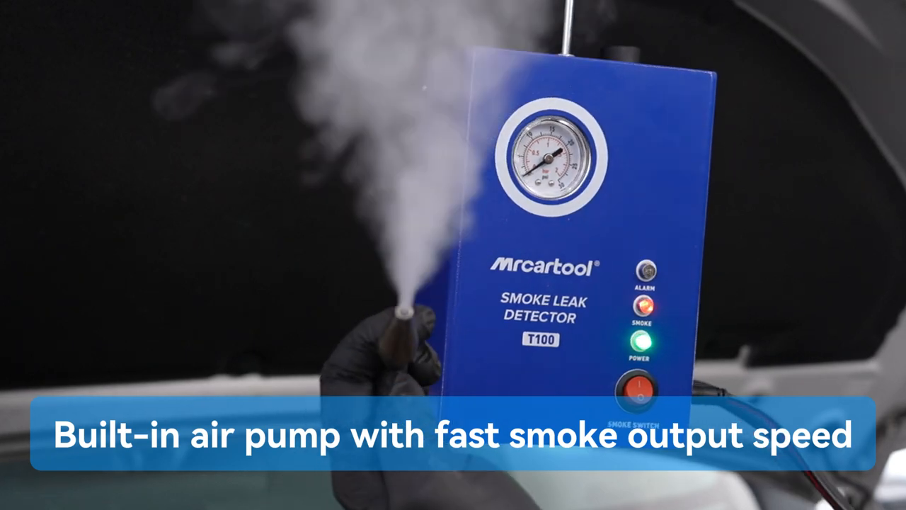
The manual says internal protection stops operation at 75°C. If the protection indicator appears or smoke stops, switch smoke mode off and let the unit cool; do not bypass the protection, repeatedly cycle a hot unit or add oil while hot. Stop immediately for burning insulation odor, smoke escaping from the case, abnormal noise or a hot/damaged power lead.
Step 6: Connect the cone without creating a false leak
When smoke is dense, insert the hose cone squarely into the prepared intake cone or selected adapter. Support the hose so it cannot lever the connection open. For a bladder adapter, follow its delivered inflation limit and make sure it seals without damaging the duct. Avoid forcing a cone into brittle plastic. Keep the T100 upright throughout the test.
Step 7: Inspect the circuit systematically
Allow smoke to fill the selected section, then inspect from the test connection outward. The manual suggests about one to two minutes and a strong flashlight. Watch couplers, hose undersides, vacuum tees, clamps, gasket lines, manifold seams and capped branches from more than one angle. Air movement can disperse a small plume, so turn off shop fans that obscure the result while preserving safe room ventilation.
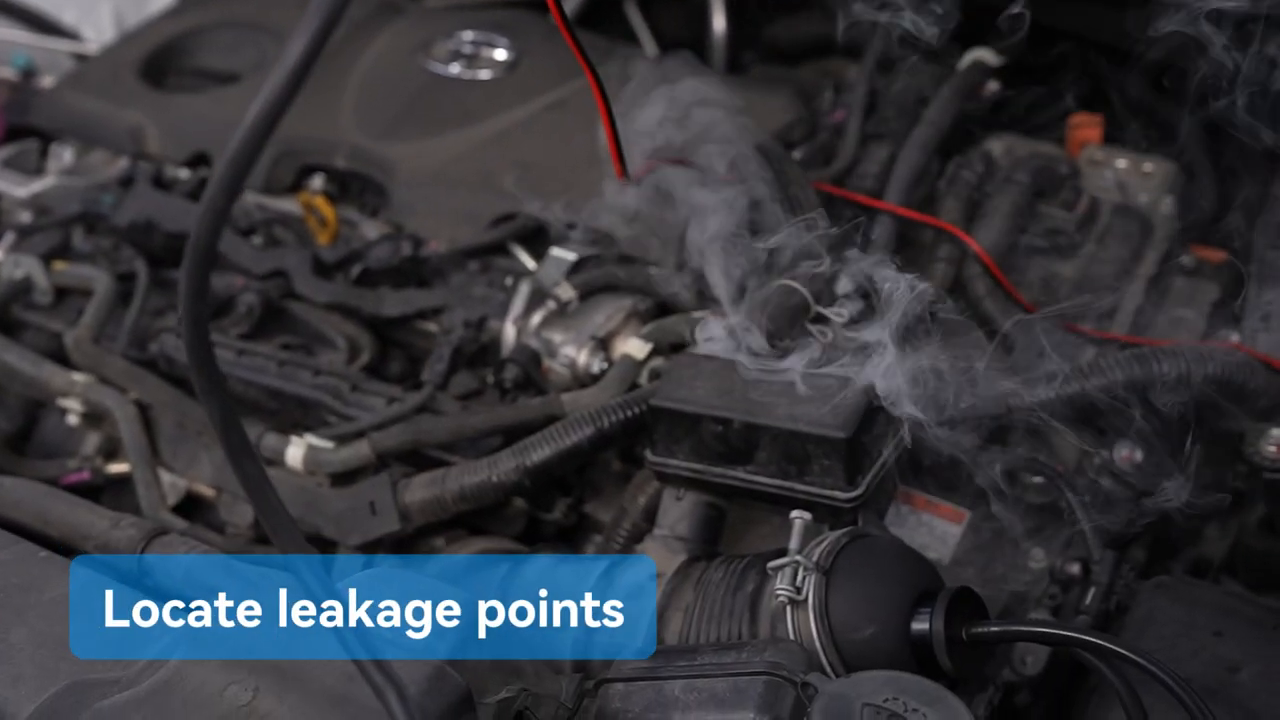
Mark the first confirmed exit point, stop smoke and repeat the test after repositioning the light or gently moving the suspect connection. A second appearance at the same origin is stronger evidence than a cloud seen once. Photograph the location and record the test boundary, adapter, gauge behavior and whether the leak persisted after the temporary connection was reseated.
How to interpret the pressure gauge and visible smoke
| Observation | Meaning to verify | Next action |
|---|---|---|
| Gauge does not rise | Large opening, unsealed test boundary or loose temporary connection | Stop; inspect cone, caps, hose and known openings before diagnosing the vehicle |
| Gauge rises then falls or wanders | Leak may exist in setup or target circuit | Use smoke and a bright light to locate the first repeatable exit |
| Gauge reaches a stable value | Connected section holds under this low-pressure condition | Do not call the vehicle leak-free if the symptom is intermittent or outside this boundary |
| Smoke at the adapter | Test-fixture leak until proved otherwise | Stop, reseat or replace the adapter and repeat |
| Smoke at a component seam | Possible vehicle leak | Confirm twice, check service information and test conditions before repair |
The pressure gauge is a screening aid, not a calibrated leak-rate result. A stable pointer applies only to the sealed section, temperature and temporary setup used during that test. Some leaks open only with vacuum, boost, vibration or heat; others disappear when a hose is moved. Combine the smoke result with fault codes, trims, vacuum or boost data and the vehicle procedure when those tests are relevant.
Step 8: Stop, disconnect and store
Press the smoke-mode switch again and confirm the smoke indicator goes out. Allow air and residual smoke to clear without opening the circuit beside your face. Disconnect black from battery negative, then red from positive. Remove the power lead, let the T100 cool, release the adapter and restore every vehicle hose, clamp, cap and air-filter part to its specified position.
- Confirm no adapter, plug, rag or temporary cap remains in the engine bay.
- Inspect the repaired or restored circuit and clear diagnostic codes only when the service procedure calls for it.
- Drain remaining test oil for long storage as directed; never drain or invert a hot machine.
- Wipe the case with a dry soft cloth and store the hose without a kink or contaminated open end.
- Record oil type and amount, battery voltage, test boundary, gauge behavior, leak location and repeat result.
Use the current MRCARTOOL manual download page if the delivered T100 labels, indicators, adapters, oil guidance or sequence differ from this guide.
Troubleshooting
| Problem | Check first |
|---|---|
| No power or pump sound | 12 V battery state, polarity, clean clamp contact, cord and T100 socket; do not open the cabinet |
| Air works but no smoke | Measured approved oil, cap, smoke switch, indicator, warm-up time and overheat protection |
| Weak smoke | Oil amount/condition, overfill, hose restriction, battery state and cooling interval |
| Gauge never rises | Open boundary, test cone, caps, hose and a major circuit opening |
| Smoke appears everywhere | Reduce the boundary, correct the connection and ventilate residual smoke before repeating |
| Protection indicator activates | Switch smoke off, disconnect safely and allow a full cool-down; never bypass protection |
Frequently asked questions
Can I run the engine during a T100 smoke test?
No. The manual requires automotive pipeline leak detection with the engine off. Also isolate ignition and let hot parts cool before introducing smoke.
Can I connect the T100 to 24 volts?
No. The documented supply is a DC 12 V vehicle battery only. Do not use 24 V or an unverified power source.
Does a stable gauge prove there is no leak?
No. It supports the connected section under one low-pressure condition. It does not exclude a small, heat-dependent, vacuum-dependent or out-of-boundary leak.
How much test oil should I add?
The manual specifies 10–20 ml and begins its setup at 10 ml. Measure it with the supplied marked bottle and use the physical level gauge; more oil is not better.
Can I use the T100 for every EVAP test?
Only when the exact vehicle procedure permits the connection and the T100’s pressure/medium. Some EVAP systems require a regulated method, scan-tool commands or a lower specified pressure.
Final T100 checklist
- Engine and ignition off; target circuit and allowed pressure verified
- T100 cool, upright, sound and supplied by DC 12 V only
- Approved oil measured at 10–20 ml; fill cap secure
- Hose, cone, plugs and target openings sealed before diagnosis
- Air/gauge pre-check completed before smoke
- Dense smoke verified; circuit inspected with a bright light
- First exit point confirmed twice and separated from adapter leakage
- Smoke stopped, power disconnected and residual pressure cleared
- All vehicle parts restored and test details recorded
The fastest smoke test is the one that avoids a false result. Define a safe circuit, prove the temporary seals with air, use only the documented oil amount and 12 V supply, then follow the smoke to its first repeatable exit. That sequence turns the T100 from a smoke source into a useful diagnostic tool.



Comments 0
Questions, fixes, and real-world diagnostic notes from readers.
Be the first to share a diagnostic result or ask a follow-up question.