
2014 Infiniti Q50 Left Turn Signal Fails: No Voltage Did Not Mean a Bad BCM

Quick answer: A missing output voltage must be interpreted at the actual contact point. A loose connector terminal can imitate a failed controller output.
A failed indicator affects how you communicate with other road users. Arrange prompt repair and do not bypass the controller, alter protection or improvise terminal repairs.
Careful passive measurement is useful here. A MRCARTOOL B550 can help check voltage at approved points, but the probe must reach the intended contact without deforming it. Supplying power to an unknown output is not a valid substitute.

In this guide
A working bulb narrowed only one possibility
If a correctly identified working lamp will not operate in the affected position, attention can move beyond the lamp itself. That is useful progress. It does not automatically distinguish among the socket, wiring, controller and other requirements of that particular circuit.
ALLDATA’s Q50 case describes a 2014 car whose left-front indicator remained inoperative with a verified bulb. Ground was present but supply was absent. A loose terminal at the body controller was found and its contact restored, returning normal operation. The connection—not a demonstrated internal BCM failure—became the repair target.
Where was the voltage actually measured?
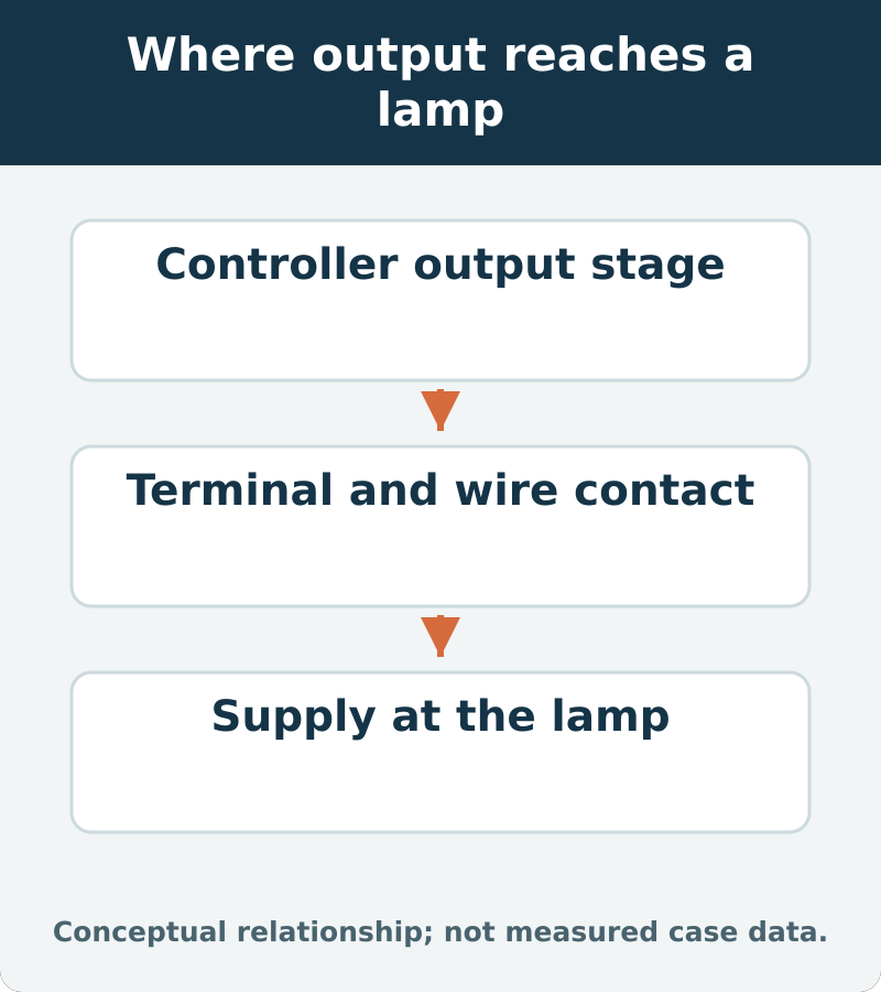
A voltage result needs an address. Was the technician observing the component side of a connection, the harness side, or a point farther along the circuit? What reference was used, and was the circuit being commanded in the relevant state? “Nothing at the BCM” leaves too many of those questions unanswered to justify a module by itself.
The contact interface matters because it sits between two places that may look almost identical on a repair sketch. A measurement on one side does not automatically describe what reaches the other. The workshop should identify the point and method in its diagnosis so the result can be interpreted without assuming that the connection between them is perfect.
| Measurement context | Question it helps answer |
|---|---|
| Identified controller-side point | Is the expected output present in the required state? |
| Mating contact and its connected path | Does that output cross the connection as intended? |
| Lamp-side point with the proper reference | What electrical support actually reaches the lamp? |
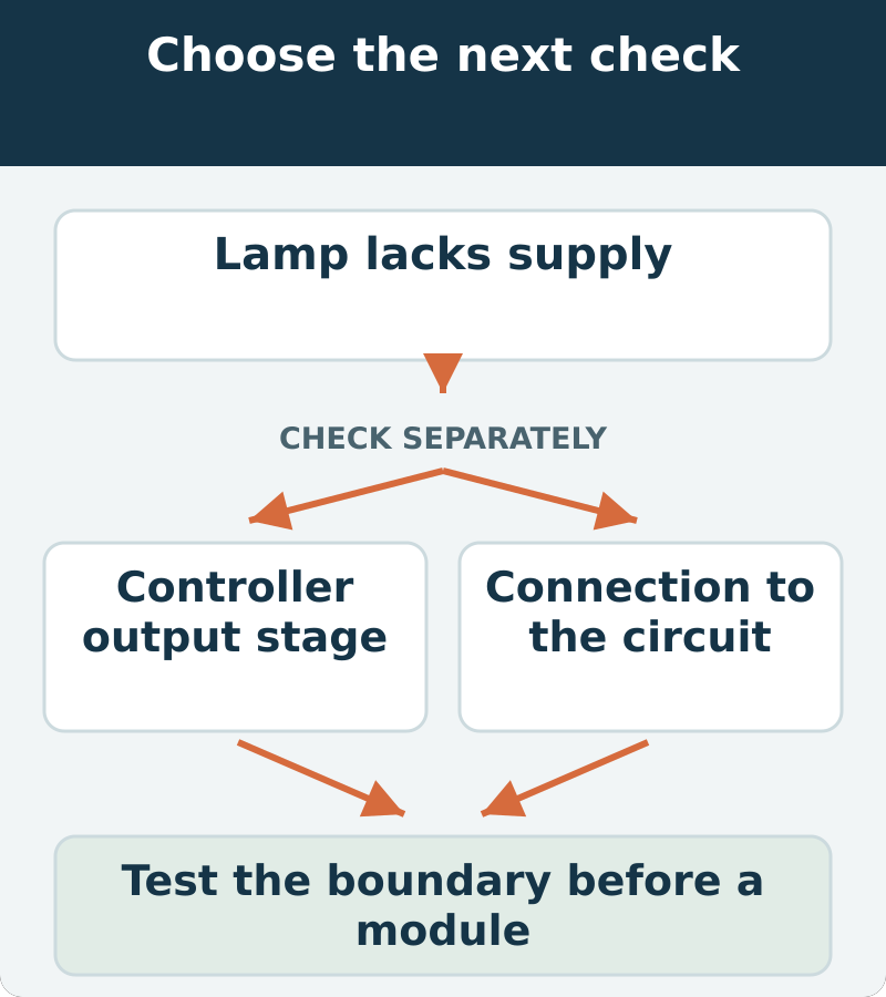
The connector belongs in the diagnosis
It is tempting to divide the world into electronic modules and wires, leaving the connector as an invisible boundary between them. In practice, that boundary is part of the circuit. Its fit and condition can determine whether a valid output reaches the intended load.
This is why a module estimate should include the relevant connector assessment. The question is not merely whether the plastic housing looked intact. It is whether the intended contact and surrounding path were evaluated by the correct method. Do not force a probe into the terminal to “make sure”; a test that changes contact shape can create a new intermittent fault while appearing to produce a reading.
Protection behavior can complicate the reading
An output may behave differently when the system detects a fault or when the conditions for operation are not met. The exact behavior must come from the vehicle’s diagnostic information. A missing voltage therefore needs interpretation alongside command state, relevant faults and the permitted test conditions, not a generic rule that absence equals a dead module.
That does not mean every missing output is normal protection. It means the technician must distinguish a commanded but undelivered output from an output that is not being requested or is being inhibited. The distinction changes where the repair belongs and helps prevent a replacement controller from inheriting an unresolved external problem.
Repair the contact to its specification
The goal is a durable connection with the required contact geometry, retention and protection. That may call for an application-specific terminal or connector repair rather than a casual adjustment. The appropriate scope depends on what is damaged and the approved repair method.
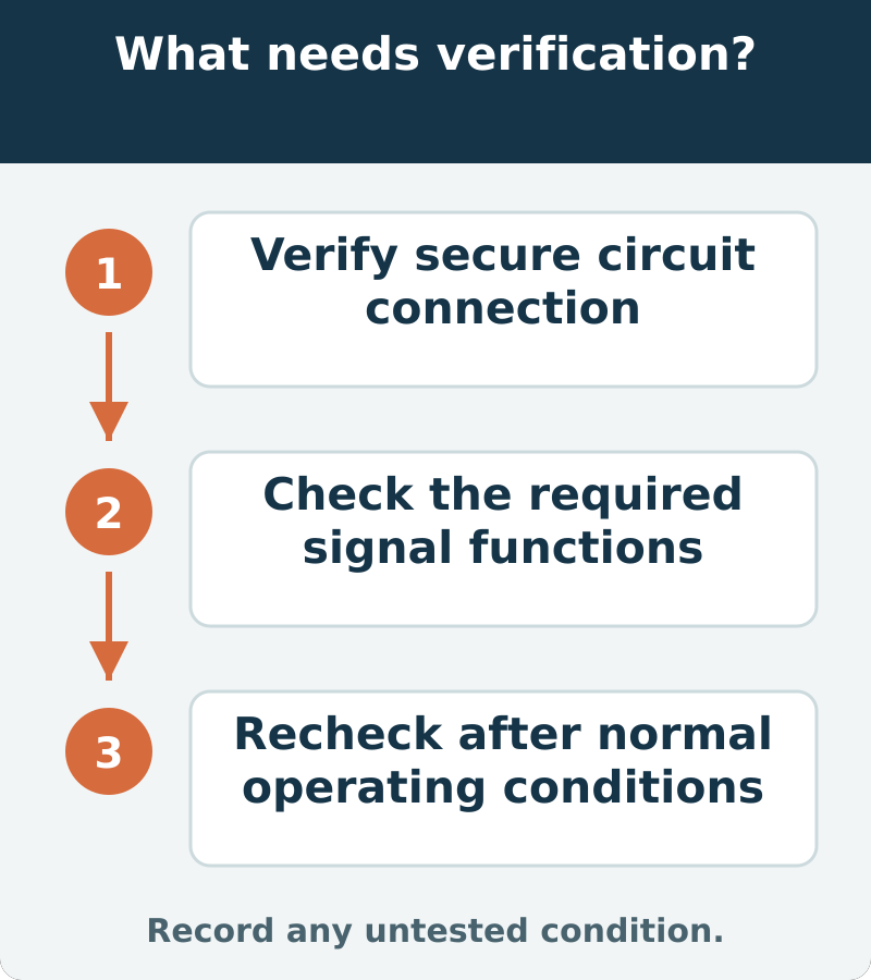
Ask the workshop what was corrected and how the connection was verified afterward. Avoid generic advice to bend, squeeze or scrape a terminal. A light that works while pressure is applied to a connector is not proof of a finished repair. The final check should reflect the assembled, secured circuit as it will operate in the car, without a probe or hand holding the connection into a favorable position.
Check the light from every normal command
Have the repaired indicator checked through the applicable normal controls, including the relevant signaling and hazard operation. The technician should also confirm the driver’s indications and any remaining fault status. Correct behavior at one brief moment does not cover every command involved in the complaint.
At handover, ask for a plain description of the localized fault and completed repair. If the problem returns, that record lets the next assessment begin at a known connection without assuming the BCM was previously replaced or proven defective. The lasting lesson is about measurement precision: knowing where a voltage is missing is as important as knowing that it is missing.










Comments 0
Questions, fixes, and real-world diagnostic notes from readers.
Be the first to share a diagnostic result or ask a follow-up question.