
2005 Dodge 3500 Stayed in First After a Rebuild: The Shift Valve Was Installed Backward

Shift Commanded, First Gear Remains
The rebuilt 48RE stayed in first gear. Because P0882 was stored and an ECM control test initially looked inactive, the transmission shop installed an ECM. Nothing changed. The productive question was simpler: did the controller request a shift, and did the hydraulic transmission produce one?
Correct breakout leads help a technician connect a meter or an appropriate test load to identified transmission circuits without piercing insulation. The AUTOOL 92-Piece Circuit Test Lead Kit is one supporting kit for that access. The 92-piece lead kit can help connect a compatible meter or load safely to identified transmission circuits without cutting wires. It cannot test hydraulic valve orientation, interpret 48RE strategy or justify grounding an ECM pin blindly.
The harness carried meaningful current, bidirectional control proved that the ECM could operate the transmission relay, and road data showed both 1–2 and 2–3 commands. Actual ratio never left first. Returning to the recently assembled valve body revealed the 1–2 shift valve installed backward; correcting its orientation restored the missing hydraulic response.
Quick answer: The ECM commanded both upshifts, but the rebuilt 48RE stayed in first because its 1–2 shift valve had been installed backward.
In this guide
- A post-rebuild fault changes the probability map
- Preserve P0882 without obeying it blindly
- Load-test the harness with meaningful current
- Use bidirectional control to test relay authority
- Commanded shifts separated request from result
- The ratio stayed fixed because hydraulics did
- Correct the reversed 1–2 shift valve
- Verify every range hot and cold
A post-rebuild fault changes the probability map
A failure immediately after major work changes the probability map without proving workmanship error. Record exactly what was removed, cleaned, reused and adjusted during the rebuild, including valve-body layout and the first road-test behavior. Verify fluid type, level and temperature by the 48RE procedure, then inspect connectors and linkage that were disturbed. Avoid blame language: it makes people defend decisions instead of sharing evidence. Recent assembly deserves early attention because it is new information, not because technicians are assumed careless.
Preserve P0882 without obeying it blindly
P0882 indicates low voltage in the transmission-control relay supply path. Save its status and operating conditions, then inspect battery voltage, fuses, relay, feeds and grounds. A low code can be caused by a genuine supply failure, excessive voltage drop, an open command path or a transient created during service. Do not treat it as an ECM purchase order. The original ECM test was interpreted as a driver that would not ground the relay, but test conditions and command strategy matter. Establish when the controller is supposed to pull the circuit low before judging silence.
Load-test the harness with meaningful current
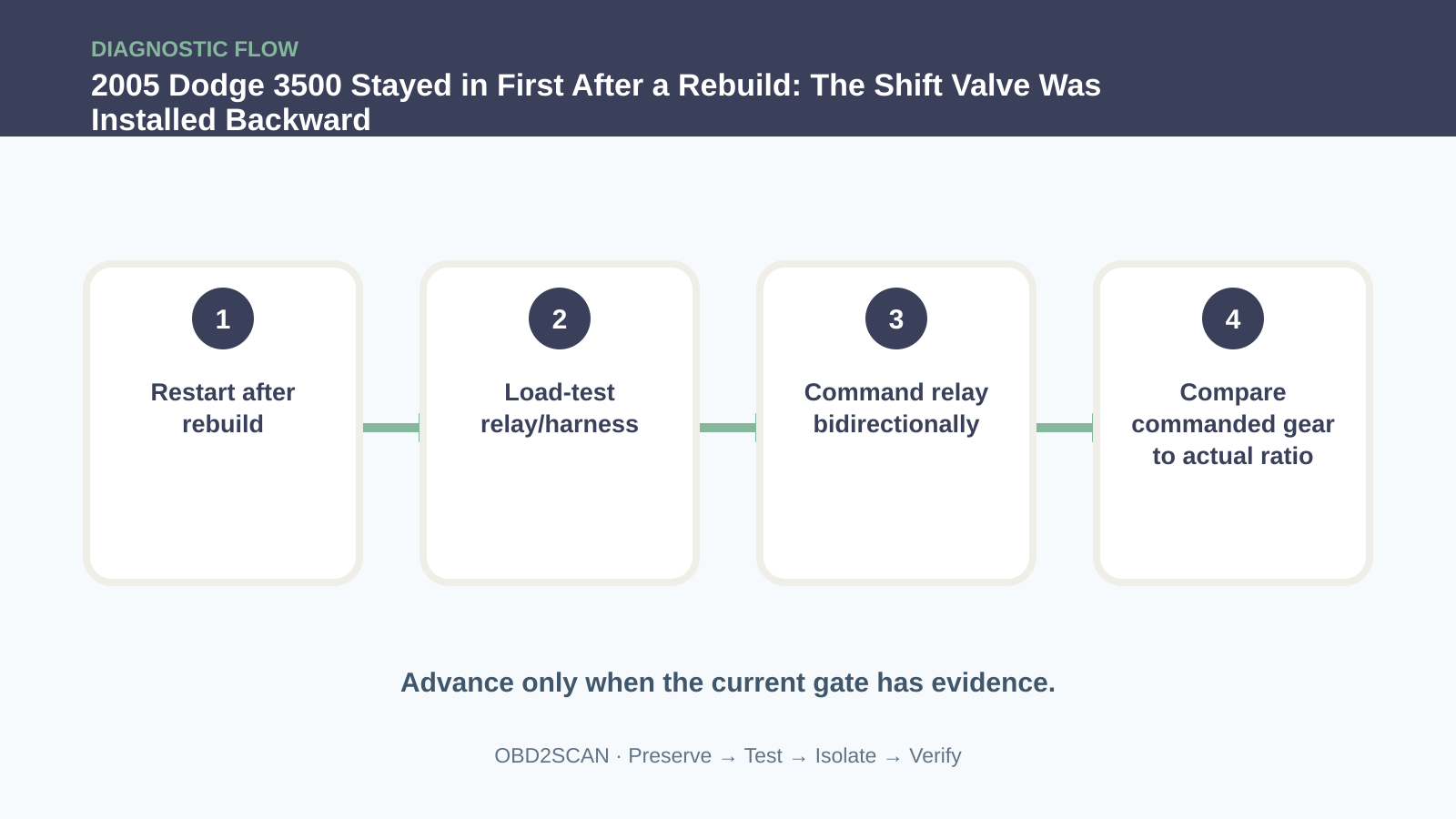
A five-amp headlamp load was connected through the identified harness path, and the circuit supported it. A load test asks whether the wire and terminals can carry useful current; an ohmmeter alone may miss a corroded connection that fails under demand. Use fused leads and a load appropriate to the circuit, disconnect modules where the service procedure requires it, and measure voltage drop rather than relying only on lamp brightness. Passing this test moved the diagnosis away from an incapable power path without claiming the relay or controller strategy was perfect.
Use bidirectional control to test relay authority
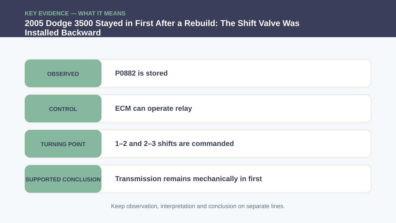
The scan tool’s bidirectional function then commanded the transmission relay, and it operated. That result demonstrated controller authority under a defined test condition and overturned the premature failed-driver conclusion. Confirm relay output at the receiving side and repeat while moving the relevant harness. A command test does not prove every ECM decision during driving, but it separates “cannot switch this output” from “may choose not to switch it under current inputs.” The replacement ECM had not helped because the original controller was capable of making the electrical request.
| Evidence | Electronic side | Hydraulic/mechanical side |
|---|---|---|
| P0882 stored | Supply path needed testing | Does not identify a valve-body fault |
| Harness passes 5 A load | Useful current reaches the circuit | No proof of hydraulic flow |
| Relay responds bidirectionally | ECM can command the relay | Transmission may still remain in first |
| 1–2 and 2–3 shown as commanded | Shift request exists on the road | Actual ratio must be compared |
Commanded shifts separated request from result
On the road, scan data showed a 1–2 command and then a 2–3 command, while turbine/output speed relationship and vehicle behavior remained consistent with first gear. That disagreement is the turning point. The controller had supplied a request; the transmission did not deliver the expected ratio. Monitor speed sensors for plausibility and stop the test before excessive rpm or heat. A commanded gear parameter describes software intent, not clutch application. Once request and result are separated, replacing more electronics becomes difficult to justify.
The ratio stayed fixed because hydraulics did
Hydraulic pressure and valve movement translate the electrical request into clutch application. Review the circuit for the 1–2 event, confirm manual-valve position and inspect the recently handled valve body. A sticking spool, misplaced checkball, separator-plate problem or incorrect valve orientation can block the route while electrical commands look normal. In this case the 1–2 shift valve had been installed backward. That physical orientation explained why the ratio could not change even though later commands appeared in scan data.
Correct the reversed 1–2 shift valve
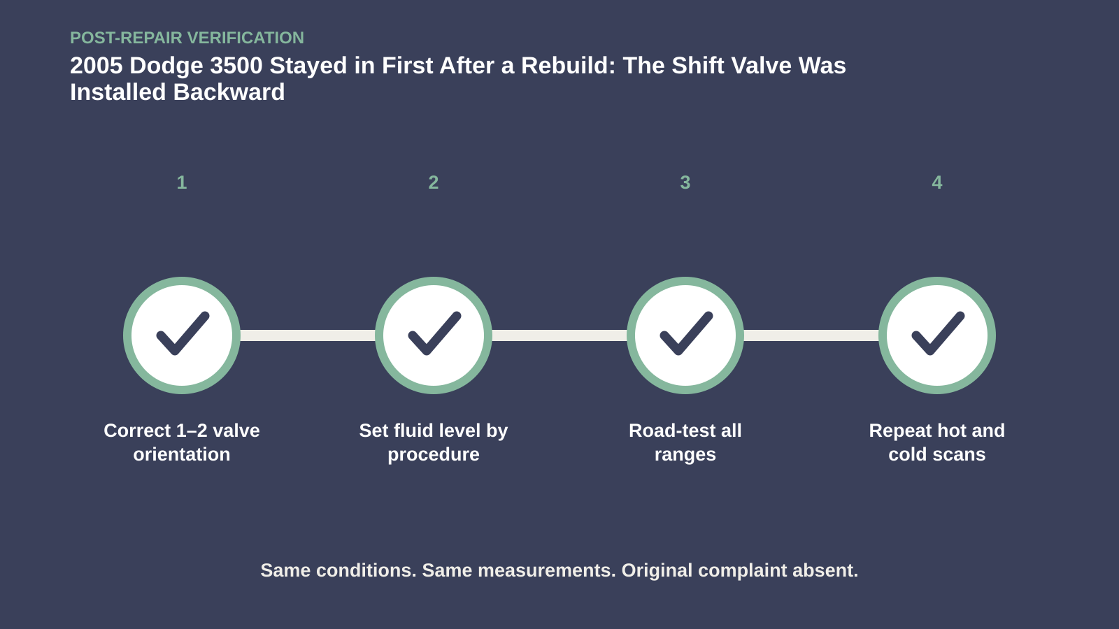
Correct the 1–2 shift valve orientation using the exact 48RE diagram, then re-inspect every adjacent spool, spring, retainer, checkball and plate location before closing the unit. Work on a clean, organized bench and record components as they leave each bore. Cleanliness matters because one piece of lint can create a new sticking valve and obscure whether the original correction worked. Replace disturbed seals as specified, torque the valve body in sequence and set fluid level only at the required temperature and operating state.
Verify every range hot and cold
Verification must include every forward shift and downshift both cold and fully warmed, manual ranges, reverse engagement and converter-clutch operation where conditions allow. Record commanded gear, actual ratio, input/output speed and relevant pressure or calculated slip. Check for P0882 and transmission pending codes after a complete drive. The repaired transmission should no longer stay in first when the 1–2 command occurs, and shift quality should remain consistent after heat soak. Reinspect fluid level and leaks before handoff, because correcting one valve is not proof that the entire rebuild is complete.
The comeback was solved by comparing instruction with outcome. Once the ECM proved it could ask and the gear ratio proved the transmission could not answer, the diagnosis returned to the last place hydraulic authority had been assembled.









Comments 0
Questions, fixes, and real-world diagnostic notes from readers.
Be the first to share a diagnostic result or ask a follow-up question.