
How to Find an Air-Suspension Leak with the AUTOOL PT680

A vehicle that sinks overnight does not immediately tell you whether the leak is in an air spring, line, connector or valve block. The AUTOOL PT680 air suspension pressure tester lets you monitor two comparable circuits at the same time, so the side that loses pressure can be separated from the side that remains stable. The quality of that answer depends on a controlled connection, equal test conditions and a verified hold period.
Quick answer: Use the vehicle’s approved depressurization and isolation procedure, connect PT680’s two channels to equivalent left/right suspension circuits, zero the tester at atmospheric pressure, charge or command the system to the specified condition, and run the same timed hold on both sides. First rule out leaks at the tester fittings; then treat a repeatable pressure drop on one channel as a direction for further isolation, not automatic proof that the air spring itself has failed.
In this guide
What the two-channel test can prove
PT680 measures pressure and pressure change. When its left and right channels are attached to equivalent circuits under the same conditions, a side-to-side comparison reduces guesswork caused by temperature, elapsed time and test setup. It can direct the next isolation step toward a spring, pipe, joint or shared component.
The test does not identify a failed part by name. A loss recorded at the tool may originate at the adapter, disconnected line, air spring, valve or another component still included in the isolated section. The vehicle’s pneumatic diagram determines what the measurement includes.
| PT680 item | Published capability | Practical meaning |
|---|---|---|
| Channels | Two synchronous pressure inputs | Compare equivalent left/right circuits over one interval |
| Range | 0–20 bar | Confirm the vehicle test stays within the instrument range |
| Accuracy | ±1% FS | Small changes must be interpreted with instrument accuracy in mind |
| Units | psi, bar, kg/cm² and kPa | Choose the unit used by service information before recording |
| Display functions | Wheel position, pressure difference, leak test and hold countdown | Label the channel and preserve equal timing |
For button functions, unit selection and basic instrument setup, see the AUTOOL PT680 controls and general-use guide; this guide concentrates on a paired air-suspension leak diagnosis.
Before you start
- Obtain the exact vehicle’s pneumatic diagram, lifting-mode instructions, safe deflation method, test pressure and permitted hold-time loss.
- Support the vehicle according to its service procedure; air suspension can change ride height without warning.
- Disable self-leveling or enter jack/service mode if the manufacturer requires it.
- Confirm both adapters match the vehicle connections and inspect hoses, seals and quick couplers.
- Install fresh batteries and keep the PT680 within its 0–20 bar range and rated operating conditions.
- Prepare a worksheet for start pressure, end pressure, elapsed time, temperature and channel position.
Never loosen an air line simply because the vehicle is switched off. Return the pneumatic circuit to the manufacturer-defined safe pressure before opening any connection.
Dual-channel air suspension leak-test procedure
Step 1: Define the two circuits being compared
Use the pneumatic diagram to choose two equivalent test points: for example, left and right rear spring circuits downstream of the same control stage. Write down every component included between each test point and the end of its isolated branch.
A comparison is only useful when both channels represent comparable sections. Connecting one channel at an air spring and the other upstream of a valve block produces different test boundaries and an ambiguous result.
Step 2: Stabilize and protect the vehicle
Place the vehicle on the specified support surface, set the parking and wheel-restraint conditions, and use approved lifting points if access underneath is required. Enter the required jack or service mode so automatic leveling cannot command an unexpected pressure or height change.
Note the starting ride-height symptom before disturbing the system. A corner that sinks, a delayed compressor run or a height warning helps define the complaint, but it does not replace pressure testing.
Step 3: Depressurize only by the approved method
Use the scan-tool or mechanical service procedure specified for the vehicle to reduce pressure in the selected branches. Verify the circuit is safe before releasing a line or service fitting. Wear eye protection and keep hands away from a body or suspension component that can move as pressure changes.
Do not vent an entire system when the procedure calls for isolating one axle or corner. Unnecessary venting changes more variables and creates additional refill work.
Step 4: Inspect and connect both PT680 channels
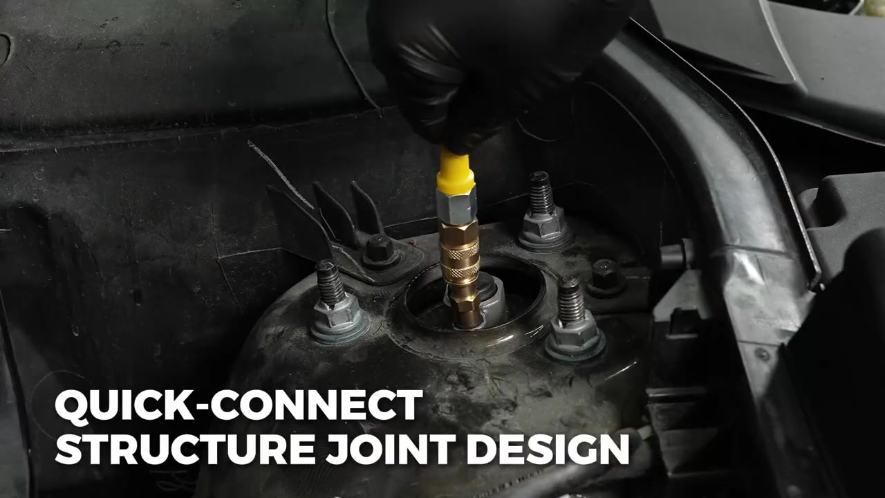
Select matching adapters, inspect each seal and push every quick connector to its fully locked position. Tug lightly on the coupling rather than assuming the audible click means it is seated. Route hoses away from hot exhaust parts, sharp edges and suspension travel.
Assign the left test point to one channel and the right point to the other, then select the corresponding wheel positions on the display. Keep the same assignment through every repeat so the worksheet and screen cannot be confused.
Step 5: Zero the tester with both inputs at atmospheric pressure
Before pressure is applied, power on the PT680, select the service-information unit and use the zero function. Both channels should start from a stable baseline. An offset, drifting zero or unstable connector must be corrected before it is attached to the diagnosis.
The published 0–20 bar range is an instrument limit, not permission to pressurize a vehicle circuit to 20 bar. The vehicle specification always controls the applied pressure.
Step 6: Prove the test rig before judging the vehicle
Bring both channels to the controlled test condition and inspect every PT680 hose, adapter and quick coupling. If permitted, use an appropriate leak-detection method at external tool connections. A changing reading caused by the test rig can look exactly like a leaking air spring.
Allow pressure and temperature to stabilize as the vehicle procedure requires. Start both channels from matched or documented values; an uncontrolled starting difference makes the differential number hard to interpret.
Step 7: Run one timed pressure hold
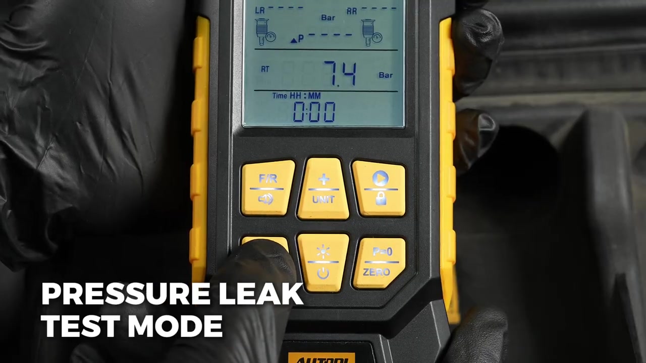
Select pressure-leak test mode, set the required interval and begin the hold without changing hoses or vehicle state. Watch both channel readings and the pressure-difference display. Record starting values rather than relying on memory.
The official demonstration shows the instrument in leak-test mode, but its displayed pressure is not a universal target. Use only the exact vehicle’s fill and loss limits. Stop if pressure exceeds the permitted value, a hose moves or the vehicle becomes unstable.
Step 8: Compare loss, not just the final number
At the end of the same interval, record both final readings and calculate each channel’s loss. A repeatable loss on one side while the matched side remains stable is strong evidence that the leaking boundary is within that branch or its tool connection.
If both sides drop similarly, inspect what they share: test-rig connections, a common supply path, valve block or the test condition itself. A pressure difference alone is not a pass/fail threshold unless the vehicle information defines one.
Step 9: Narrow the leaking boundary and repeat
Move the test boundary one component at a time as the pneumatic diagram allows. For example, isolating the line from the spring can separate a spring leak from an upstream pipe or valve leak. Re-zero after changing the setup and repeat with the same pressure, time and temperature conditions.
A conclusion should survive a repeat run. If the suspected side changes when hoses are exchanged, inspect the PT680 channel, hose and adapter before replacing a vehicle part.
Step 10: Return the system to service safely
End the test, command or bleed the circuit to its safe disconnection state and verify zero pressure at the opened section. Remove each connector without side loading, reinstall the original line or seal and inspect the connection.
Restore normal leveling mode, refill the system by the approved procedure, clear only faults addressed by the repair and perform a final ride-height and leak check. Record the repaired boundary and the post-repair hold result.
How to interpret the pressure-hold pattern
Read the pattern as evidence about the isolated test boundary, then confirm it by changing only one variable.
| Observed pattern | Most useful interpretation | Next check |
|---|---|---|
| One channel drops; the other is stable | Loss is limited to one branch or its tool connection | Leak-check that side and subdivide its boundary |
| Both channels drop similarly | A shared path, setup issue or common condition is possible | Check tool connections and upstream common components |
| Loss follows the hose after channels are exchanged | Tester hose, adapter or channel is suspect | Repair the test rig before vehicle diagnosis |
| Pressure is stable but vehicle still sinks | The tested boundary or condition did not reproduce the fault | Test another branch and consider temperature or valve-command conditions |
Air suspension stores energy and can move the vehicle body unexpectedly. Use approved support, control automatic leveling and verify a safe pressure state before every disconnection. Never work under a vehicle supported only by its air springs.
Common mistakes
- Using the example pressure shown in a video as the vehicle specification.
- Comparing two test points that include different components.
- Skipping the tool-side leak check before blaming an air spring.
- Opening a pressurized line because the ignition is off.
- Changing pressure, time and hose assignment between comparison runs.
- Calling a pressure drop an air-spring failure without isolating the line and valve path.
Frequently asked questions
Can PT680 test the left and right air springs at the same time?
Yes. Its two channels are designed for synchronous comparison, provided the adapters and selected test points are correct for the vehicle.
What pressure should I use for an air suspension leak test?
Use the exact vehicle service specification. The PT680 range and a number shown during a demonstration are not vehicle target pressures.
Does a falling channel prove the air spring is leaking?
No. It proves pressure is leaving the isolated boundary, which may include a fitting, hose, spring, pipe or valve. Narrow the boundary and repeat.
Why should I test both channels under the same temperature?
Gas pressure changes with temperature. Equal timing and similar temperature make a left/right loss comparison more meaningful.
Can PT680 be used as an engine pressure tester?
No. The current product record identifies PT680 for vehicle air-suspension pressure leak checks, not cylinder, fuel, oil, transmission or brake testing.
Pressure-leak test record
- Vehicle safely supported and leveling control placed in the required mode.
- Equivalent left/right test boundaries identified on the pneumatic diagram.
- Both channels zeroed and tool connections proven leak-free.
- Starting pressure, ending pressure, interval, unit and temperature recorded.
- Abnormal branch subdivided and the result repeated before parts replacement.
- System safely reconnected, refilled and checked at normal ride height.
PT680 is most valuable when both channels are treated as a controlled experiment. Match the test boundaries, hold every other condition steady, and move the boundary only after a repeatable loss pattern appears. That turns an overnight sag complaint into a defensible next diagnostic step.








Comments 0
Questions, fixes, and real-world diagnostic notes from readers.
Be the first to share a diagnostic result or ask a follow-up question.