
How to Use the AUTOOL LM120+ Digital Manifold Gauge

Use the AUTOOL LM120+ by confirming the refrigerant and vehicle procedure, closing both manifold valves, checking the pressure rating of every hose and adapter, installing four AA batteries, selecting the correct refrigerant and units, and zeroing both disconnected channels at atmosphere. Connect the two wired temperature clamps only after you have assigned T1 and T2 to the correct pipe locations, then capture pressures, saturation temperatures, pipe temperatures, superheat and subcooling under one stable operating condition.
The LM120+ combines a dual-channel digital manifold, an 89-refrigerant pressure-temperature reference, two wired temperature inputs, relative-vacuum mode and a timed pressure-change test. It assists measurement; it does not identify an unknown refrigerant, choose the vehicle charge mass, certify deep evacuation or locate a leak by itself.
In this guide
What makes the LM120+ workflow different
The AUTOOL LM120+ adds a practical temperature-clamp workflow to the familiar high- and low-side pressure display. After the correct refrigerant is selected, the gauge converts pressure into evaporation (EV) and condensation (CO) saturation temperatures. With T1 and T2 clamped to the specified pipes, it can display actual pipe temperature and calculate superheat (SH) and subcooling (SC).
Those results are useful only when the refrigerant, probe location, airflow, compressor state and operating load are known. Treat the full data set as one observation rather than using a single pressure or calculated value as a charging command.
Before you connect the gauge
Open the AUTOOL manual download center and match the shared LM120/LM120+ manual to the instrument in front of you. Obtain the exact refrigerant, charge specification, service-port map, diagnostic test condition, recovery and evacuation procedure from the vehicle or equipment information.
Inspect the delivered package instead of relying on a comparison chart. The current product information describes two wired temperature clamps, but bundles and replacement accessories can change. Confirm that each clamp connector fits the exact LM120+ and that the hoses, couplers and adapters are compatible with the system and refrigerant.
Use ventilation, eye and hand protection, rated low-loss couplers and compliant recovery/service equipment. Keep hoses and clamp leads away from fans, belts, exhaust parts and electrical terminals.
Stop: Do not connect an unknown or contaminated system, use oxygen or shop air for pressure testing, vent refrigerant to clear a hose, exceed the lowest component rating, or open a manifold valve until you have traced the center path.
Understand the LM120+ controls
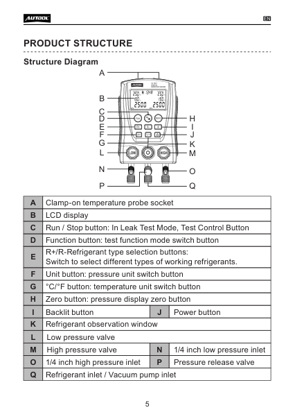
The blue knob controls the low-side path and the red knob controls the high-side path. The lower fittings are low side, center service/vacuum source and high side. The keys select Function, Run/Stop, refrigerant R+/R-, pressure Unit, °C/°F, Zero, backlight and power. The screen changes meaning in pressure, vacuum and timed-test modes, so read the mode symbols before interpreting a number.
LM120+ step-by-step operating procedure
Step 1: Define the test and acceptance data
Choose a running pressure-temperature diagnosis, procedure-controlled evacuation observation or an approved isolated pressure-change test. Record refrigerant, connection diagram, system state, ambient conditions, target values, stabilization time and shutdown method.
Completion check: Every connection and acceptance value comes from exact vehicle or equipment information.
Step 2: Inspect the LM120+ and complete pressure path
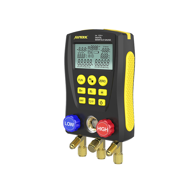
Close both valves. Inspect the housing, screen, sight window, pressure-release hardware, three fittings, clamp socket, brass threads, hoses, couplers, gaskets and valve stems. Replace damaged, contaminated or hardened parts.
The manual lists a manifold measurement range up to 6 MPa, but an included hose can have a lower working limit. The lowest-rated manifold, hose, adapter, coupler or system component controls the job.
Completion check: The complete path is clean, closed, compatible and rated for the expected state.
Step 3: Verify the Plus clamp and hose bundle
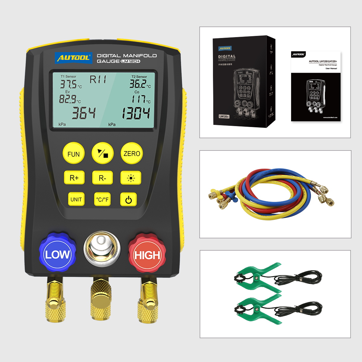
Lay out the two temperature clamps and hoses actually delivered. Check connector fit, insulation, jaw spring force and sensor surfaces. Label the clamps T1 and T2 if the leads are not already unmistakable, and record which pipe each channel will measure.
Completion check: Both temperature channels and all three hose paths can be identified without relying on color alone.
Step 4: Install four AA batteries
Install four matched 1.5 V AA/LR6 batteries with correct polarity. Power on and check the low-battery icon, complete screen segments, backlight and keys.
Completion check: The display is stable and battery condition can support the full test.
Step 5: Select refrigerant and display units
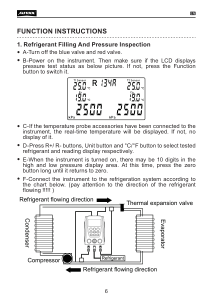
With both valves closed and pressure inlets disconnected, use R+/R- to select the refrigerant verified from the service information. Choose the same pressure and temperature units used by the job sheet.
Completion check: Refrigerant and units match the written vehicle data exactly.
Step 6: Zero both channels at atmosphere
Leave both pressure inlets open to clean atmospheric pressure. Hold Zero until residual digits return to zero. Never zero a channel with a hose under pressure or vacuum. Persistent offset requires setup or instrument evaluation.
Completion check: Both disconnected channels read zero before service connection.
Step 7: Connect and map T1 and T2
Seat both compatible clamp connectors without twisting the leads. Clamp each sensor to the clean metal pipe location specified by the procedure, not over insulation or a fitting. Ensure full jaw contact, assign the displayed T1 and T2 values to the correct pipes, and route the leads safely.
Completion check: Each live temperature belongs to a named pipe location and remains stable when the lead is moved gently.
Step 8: Hang the manifold and trace every hose
Hang the LM120+ upright where the display and sight window remain visible. Trace blue to the verified low-side service port, red to high side and the center path to the required recovery, vacuum or charging equipment. Follow the vehicle and coupler instructions for connection order; keep both manifold valves closed.
Stop: If a coupler resists, a fitting leaks, a hose warms or bulges, or its destination is uncertain, isolate the system and correct the setup.
Completion check: Every hose is traced end to end and no valve has been opened unintentionally.
Step 9: Establish one repeatable operating condition
For diagnosis, set engine speed, blower, doors, airflow load, fan command and ambient measurement exactly as required. Observe from a safe position and wait for compressor operation, pressures and temperatures to stabilize.
Completion check: The operating state and ambient conditions are recorded before the data snapshot.
Step 10: Capture pressure, EV and CO together
Record low-side pressure, high-side pressure, evaporation saturation temperature and condensation saturation temperature at the same moment. If either side changes rapidly, continue observing rather than selecting a convenient instant.
Completion check: Both pressure channels and both calculated saturation values belong to one stable test condition.
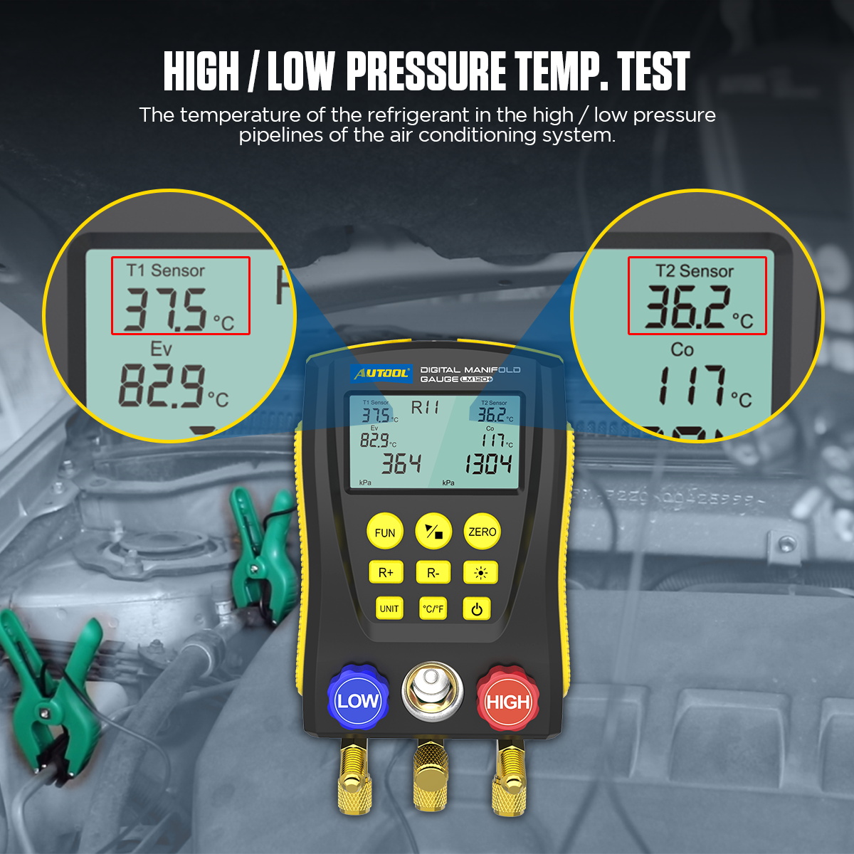
Step 11: Verify T1, T2, SH and SC
Record both pipe temperatures and the displayed SH and SC. Verify the calculation direction against the pipe locations: superheat relates suction-line temperature to evaporation saturation, while subcooling relates condensation saturation to liquid-line temperature. A swapped clamp can produce a believable but useless result.
Compare the complete data set with the vehicle diagnostic procedure. Recheck refrigerant selection, probe contact, airflow and compressor control before considering a charge correction.
Completion check: SH and SC are supported by identified pipe locations, stable pressures and correct refrigerant data.
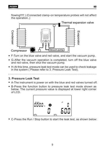
Step 12: Use timed pressure-change mode only in an approved test
Enter the pressure test screen with Function. Run/Stop records initial pressure, current pressure, difference and elapsed time. Use only the specified test medium, regulated pressure, stabilization period and acceptance limit. Record temperature because it changes pressure.
Completion check: Medium, pressure, temperature, duration and decision rule all match the exact procedure.
Step 13: Treat relative vacuum as a gross trend
In Vacuum mode, connect the center path to compliant evacuation equipment and follow the specified isolation sequence. The LM120+ reports coarse relative vacuum, not documented micron-level absolute pressure. Use a dedicated absolute vacuum gauge and the required decay test when the service procedure calls for deep-vacuum acceptance.
Completion check: Evacuation is accepted with the specified absolute method, not from the percentage display alone.
Step 14: Isolate, disconnect and store
Return the service equipment and system to the prescribed shutdown state. Close both LM120+ valves, manage trapped refrigerant through approved recovery or low-loss equipment, disconnect in the required order and reinstall service-port caps. Clean the clamp contact surfaces, protect fittings and remove batteries for extended storage.
Completion check: No refrigerant was intentionally vented, all ports are restored and the complete reading set is saved to the job.
Reliable LM120+ data gates
| Gate | Pass condition | Stop or repeat when |
|---|---|---|
| Identity | Refrigerant and units are verified | Refrigerant is guessed from pressure |
| Setup | Valves closed, paths traced, atmospheric zero complete | A channel was zeroed while connected |
| Clamps | T1 and T2 have full contact at named pipe locations | A probe is loose, insulated or swapped |
| Condition | Load, airflow and compressor state are stable | Readings come from changing conditions |
| Decision | Pressure, saturation, pipe temperature, SH and SC agree with vehicle data | One value drives a charging decision |
Common LM120+ problems
T1 or T2 is blank or unstable
Reseat the correct clamp connector, inspect the lead and ensure the jaws contact clean metal fully. Swap channels only as a controlled check and record the change; do not lose pipe identity.
SH or SC is implausible
Recheck refrigerant selection, T1/T2 mapping, pipe location, metal contact and system stability. Confirm the service procedure actually expects the measured condition before changing refrigerant quantity.
A channel will not zero
Disconnect every pressure and vacuum source, release trapped pressure through approved service equipment and let the gauge stabilize. Persistent offset needs evaluation rather than a mental correction.
Pressure changes during the timed test
Record temperature and inspect the external hoses, couplers, gaskets and valves first. A pressure trend does not identify the leak location or prove that the vehicle circuit is responsible.
AUTOOL LM120+ FAQ
Does LM120+ automatically identify refrigerant?
No. You select one of the built-in datasets after verifying refrigerant identity from reliable service information.
Are the temperature clamps always included?
Current product information describes two wired temperature clamps, but packages can vary. Verify the exact bundle and connector compatibility before the job.
Can the relative-vacuum display replace a micron gauge?
No. Use the absolute vacuum gauge, stabilization time and decay criterion required by the procedure.
What batteries does LM120+ use?
Four 1.5 V AA/LR6 batteries.
The reliable LM120+ workflow
Verify the job data, inspect and close the manifold, confirm the actual Plus clamp bundle, install four AA batteries, select the exact refrigerant and units, zero both open-air channels, map T1 and T2 to documented pipe locations, trace all hoses, stabilize the system and capture pressure, saturation, pipe temperature, SH and SC together. Use timed and vacuum modes only within their measurement limits, then isolate and disconnect without venting. That sequence makes the added temperature channels useful diagnostic evidence instead of extra numbers on the screen.











Comments 0
Questions, fixes, and real-world diagnostic notes from readers.
Be the first to share a diagnostic result or ask a follow-up question.