
How to Use the AUTOOL HTS518 Walnut Blasting Machine

Use the AUTOOL HTS518 only after the target intake valve is confirmed fully closed, every neighboring opening is protected, and the selected adapter seals the intake port. The safe result is not “blast for a fixed number of minutes.” It is controlled carbon removal followed by complete abrasive recovery, a lighted inspection, correct reassembly, and a successful leak and diagnostic check before the vehicle returns to service.
HTS518 combines an external-air walnut blasting path with powered vacuum recovery. The machine can help remove hard carbon from accessible intake-port and intake-valve surfaces, but it does not replace vehicle-specific instructions for manifold removal, crankshaft rotation, valve position, component protection, torque, or restart checks.
In this guide
What the HTS518 can—and cannot—do
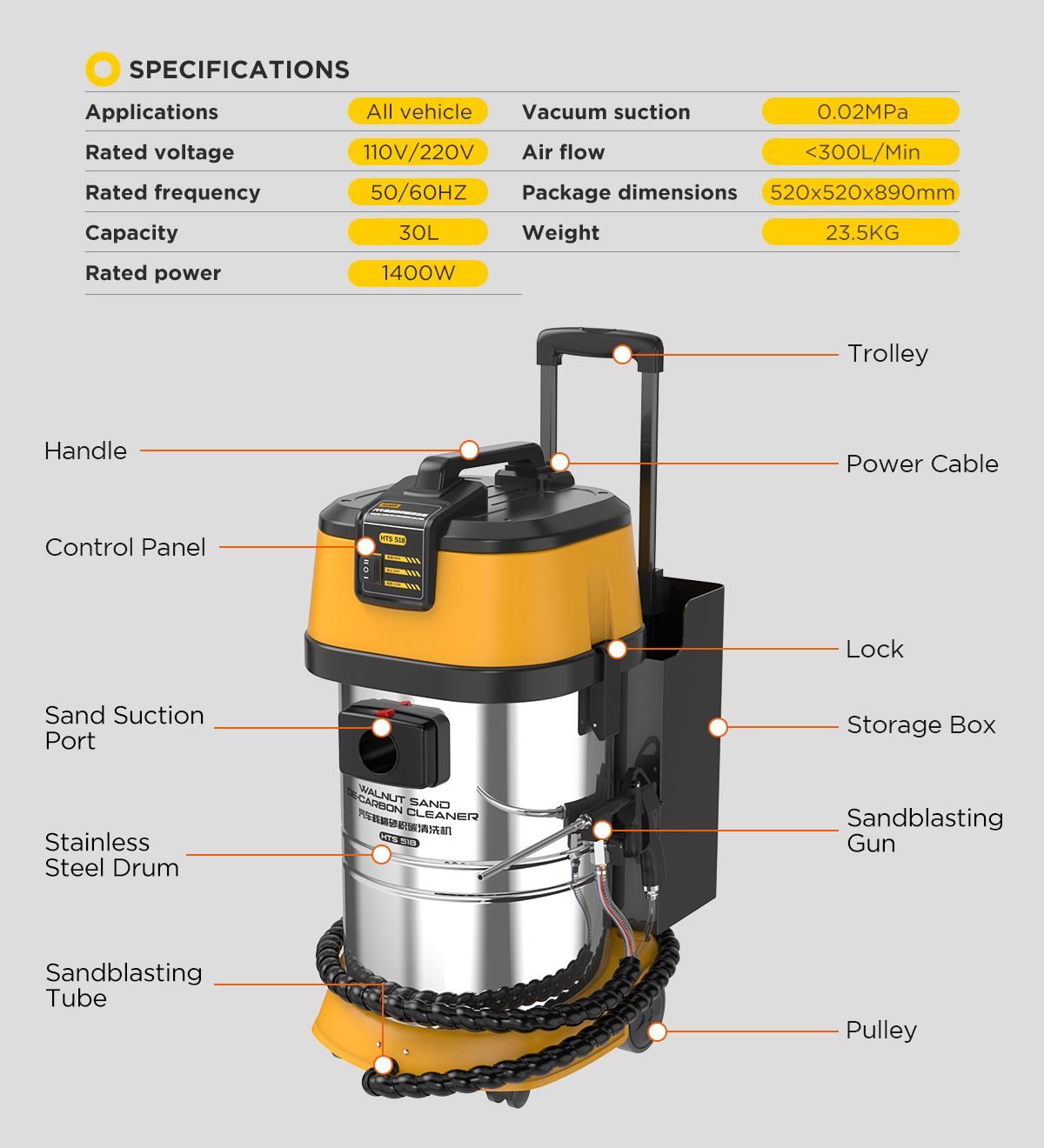
The AUTOOL HTS518 uses walnut-shell abrasive to loosen deposits while its recovery path collects media and residue. Its 30 L body, 1400 W recovery motor, high/low recovery control, external-air connector, blasting gun, recovery hose, and adapter set form one sealed cleaning system.
It is intended for supported intake-port and intake-valve cleaning. It is not a substitute for diagnosis, and it is not permission to blast an open valve, a throttle body, a fuel injector, an assembled cylinder, or any surface the vehicle maker does not approve for this method. A cleaner-looking valve does not by itself prove that a drivability fault is repaired.
The most important boundary is the engine opening. Walnut media must stay out of the cylinder, oil circuit, coolant circuit, electrical connectors, and neighboring ports. If you cannot prove the target valve closed and the port isolated, stop before adding compressed air.
Before you start
Use the AUTOOL manual download center to obtain the manual for the delivered machine revision. Then obtain the vehicle manufacturer’s procedure for intake access, crankshaft rotation, valve-position confirmation, port protection, gasket renewal, tightening sequence, torque, adaptation, and post-service checks.
Prepare:
- dry, new, unopened walnut-shell abrasive that matches the delivered HTS518 manual and machine;
- an external compressor, air treatment, hose, couplers, and settings that satisfy the delivered machine and workshop requirements;
- the correct HTS518 recovery elbow, blasting tube, gun, recovery hose, and port adapter;
- safety glasses or a face shield, suitable gloves, hearing protection, respiratory protection selected from the abrasive SDS and risk assessment, and workshop ventilation;
- intake plugs, lint-free protection, adequate lighting, a borescope when needed, a vacuum approved for the task, and containers for contaminated media;
- replacement intake seals and every vehicle-specific installation tool.
Place the machine on a stable, dry floor in a clean, bright, ventilated work area. Confirm its nameplate voltage matches a grounded outlet. Inspect the power cord, switch, latches, filter, bucket, hoses, gun, nozzle, couplers, adapters, seals, and wheels. Keep bystanders clear.
Stop: Do not use the machine with a damaged cord, missing ground, blocked or missing filter, split hose, loose connector, damaged adapter, wet abrasive, unstable compressor, unknown valve position, or unprotected engine opening.
Understand the machine before loading abrasive
Locate the stainless media bucket beneath the head, the filter cartridge, head latches, recovery-hose connection, blasting hose and gun, external-air connector, accessory compartment, power cable, casters, and high/low/off recovery switch. The electric motor powers recovery; the external compressor supplies the blasting air.
The blasting tube belongs inside the recovery elbow so abrasive enters the sealed target port while vacuum draws spent media and carbon back toward the machine. A powerful compressor cannot compensate for a poor seal, wrong adapter, open valve, wet media, blocked filter, or incorrect nozzle position.
Before every job, trace both paths by hand with power and air disconnected: compressor to gun to nozzle, then port adapter to recovery elbow to hose to filter and bucket. Every connection must be secure and strain-free.
HTS518 step-by-step operating procedure
Step 1: Diagnose first and preserve a baseline
Confirm that intake carbon is relevant to the complaint using the vehicle’s diagnostic process. Record fault codes, misfire data, fuel trims, idle behavior, compression or leak-down results where applicable, and a borescope image of each accessible port. Rule out ignition, injector, mechanical, boost, vacuum, sensor, and control faults as the vehicle procedure requires.
Label every intake runner and keep removed connectors, lines, brackets, fasteners, and seals organized. A before/after image is useful only when it shows the same port under comparable lighting and angle.
Completion check: The reason for cleaning, target ports, baseline condition, and required post-service checks are documented.
Step 2: Isolate energy and gain approved intake access
Allow the engine to reach the temperature required by the vehicle procedure. Isolate electrical and fuel-system energy where specified. Remove the intake manifold or other access components exactly as instructed, protecting open lines and electrical connectors from debris.
Cover every port that is not being inspected. Never rest tools, fasteners, media bags, or loose seals where they can fall into an opening. Inspect the exposed surfaces for damage, liquid, foreign material, or a condition that makes blasting inappropriate.
Completion check: The target ports are accessible, all other openings are protected, and the vehicle procedure permits walnut blasting on the exposed surfaces.
Step 3: Assemble the HTS518 blasting and recovery path
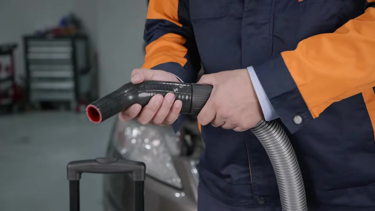
With the machine unplugged and the air line disconnected, fit the recovery hose to the machine’s recovery connection. Install the recovery elbow on the free end. Select the long or short blasting tube for safe access, secure it to the gun, and place the tube through the elbow’s opening so the blast stays inside the recovery path.
Choose the adapter by the actual port geometry—not by vehicle badge alone. The adapter must cover the opening, keep the blasting tube movable, avoid nearby components, and maintain vacuum without being forced.
Common mistake: Holding the gun beside the vacuum hose. The nozzle must operate through the recovery elbow so blast and capture work at the same sealed port.
Completion check: The blast path and recovery path are secure, the tube moves without scraping the port, and the adapter can seal without side load.
Step 4: Load fresh, dry walnut abrasive
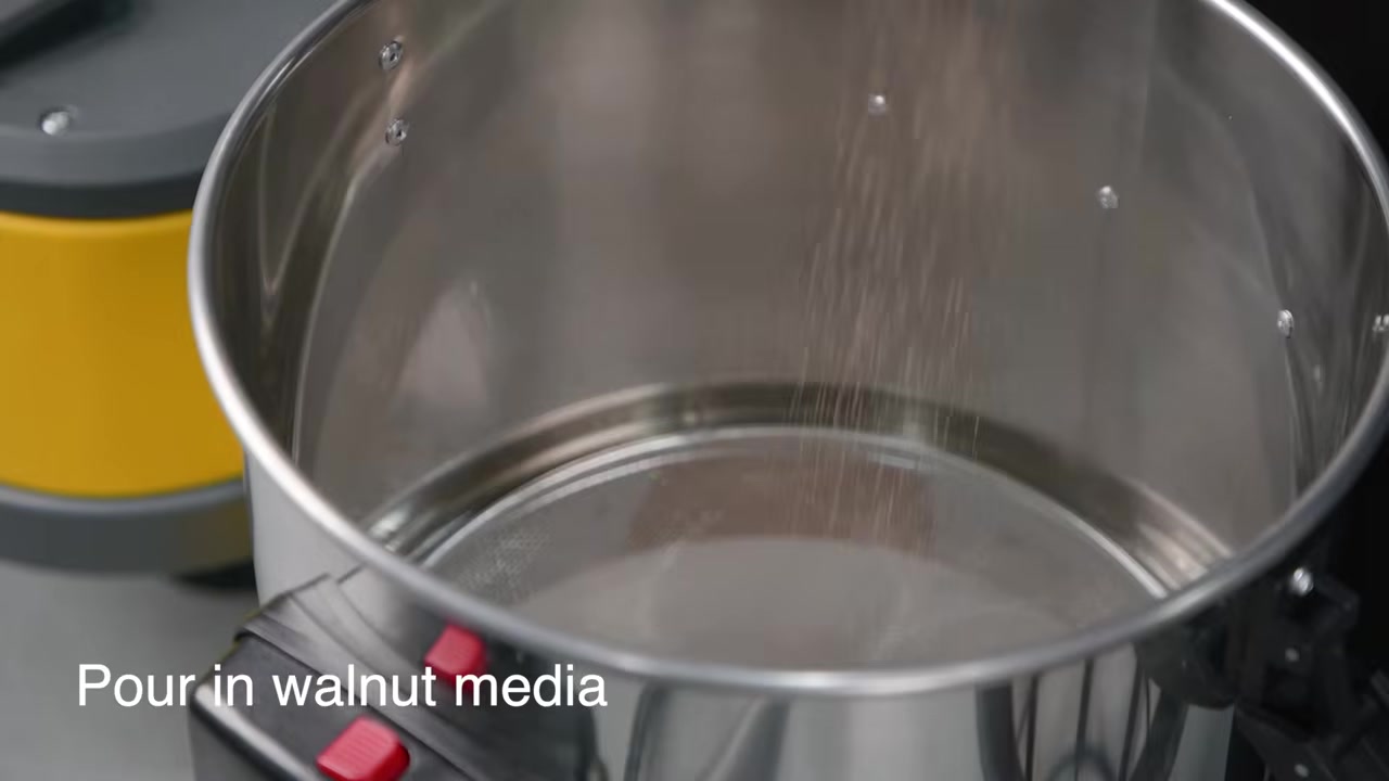
Release both head latches and lift the head according to the manual. Remove the filter cartridge without contaminating its clean side. Inspect the bucket: it must be dry and free of old debris, liquid, clumps, metal, glass, or unknown media.
Add new, unopened walnut abrasive that meets the HTS518 requirement. The manual recommends more than 2 kg. Treat that as a starting minimum, not permission to overfill; the delivered bucket, filter clearance, media condition, and current instructions determine the safe working load. Refit the filter correctly, seat the head, and close both latches evenly.
Stop: Do not mix grades, add wet or previously contaminated media, run without the filter, or fill so high that the filter or airflow is obstructed.
Completion check: The correct dry abrasive is in a clean bucket, the filter is seated, and both latches are secure.
Step 5: Connect external air and grounded power
Verify the gun valve is released and the recovery switch is Off. Connect dry, filtered external air to the machine’s air connector using compatible hose and couplers. Configure the compressor only from the current HTS518 instructions, the compressor limits, the media requirement, and the workshop risk assessment; do not copy a pressure from a different HTS model or online video.
Connect the HTS518 to a grounded outlet that matches its nameplate. Route air and power lines away from hot, sharp, moving, and wet areas. Keep them out of walking and lifting paths.
Stop: Disconnect if a coupler leaks, the hose whips, pressure is unstable, moisture reaches the media path, grounding is uncertain, or the nameplate and supply do not match.
Step 6: Prove the target intake valve fully closed
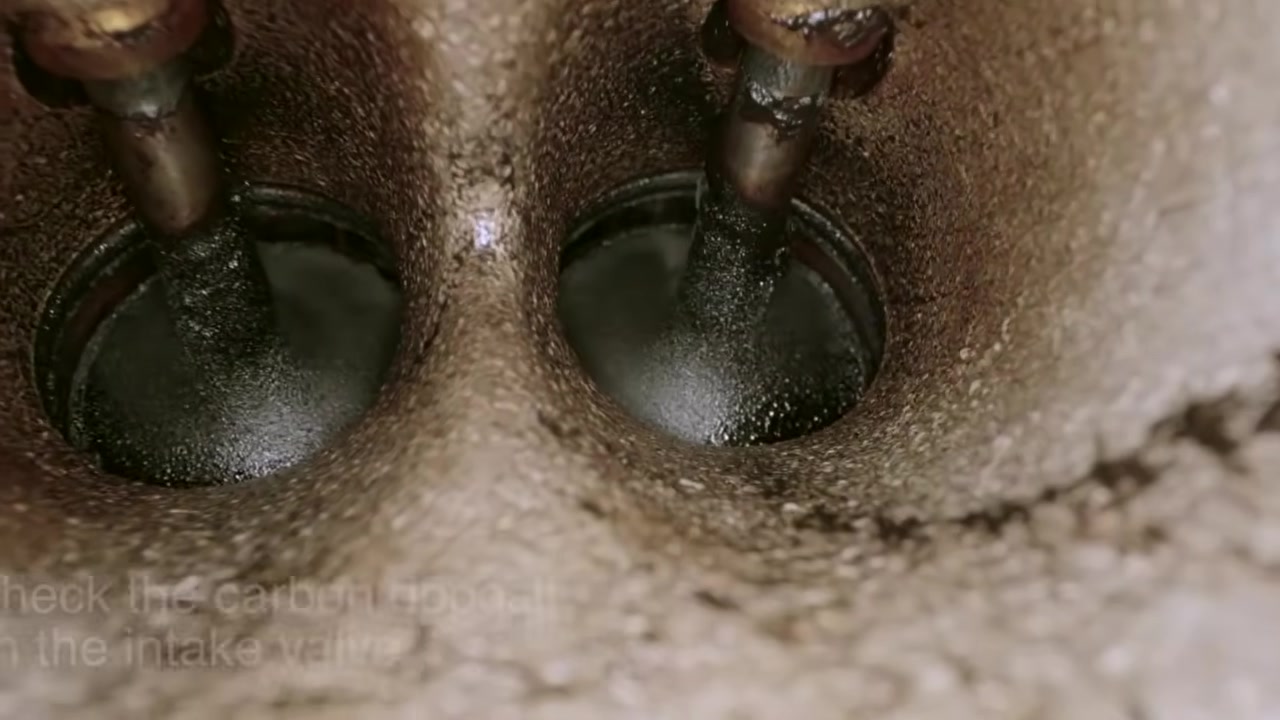
Rotate the engine only by the vehicle-approved method and direction. Use the manufacturer procedure, cam or crank reference where available, direct visual inspection, and a borescope when needed to confirm the target intake valve is fully seated. Do not infer closure because one nearby valve appears closed or because the piston seems to be at a particular height.
Protect every neighboring runner and opening before cleaning one port. If liquid is present, if the valve cannot be seen, or if valve position is ambiguous, stop and resolve the condition before connecting the adapter.
Stop: Never rely on compressed air, vacuum sound, or abrasive flow to test whether a valve is closed. That test can put media into the cylinder.
Completion check: The exact target valve is visibly and procedurally confirmed closed, and all other openings are sealed against stray media.
Step 7: Seal the adapter and check recovery before blasting
Seat the matched adapter squarely over the target port. Support the hose so it does not pull the seal open. Move the recovery switch to Low first and listen for stable recovery. Check the adapter perimeter, hose, elbow, and machine connection for leakage or collapse.
Use High only when the delivered manual, observed recovery, media load, and adapter seal call for it. High and Low control the recovery motor; they are not engine-specific cleaning programs.
Pass condition: The adapter stays sealed, the recovery hose remains open, the filter path sounds stable, and no nearby cover or loose object moves toward the port.
Step 8: Clear the nozzle with air before feeding abrasive
Aim the sealed nozzle into the approved target area with recovery already running. Before and after a cleaning pass, use a short air-only purge only as allowed by the current procedure to confirm the nozzle is clear and to reduce clumping. Keep the tube tip off the metal surface.
If flow pulses, stops, or sounds restricted, release the gun, switch the machine Off, isolate air and power, and inspect the nozzle, hose, media dryness, filter, and bucket. Do not strike the hose or increase pressure to force a blockage through the engine opening.
Completion check: Airflow is stable, the nozzle is clear, and recovery remains sealed before abrasive reaches the port.
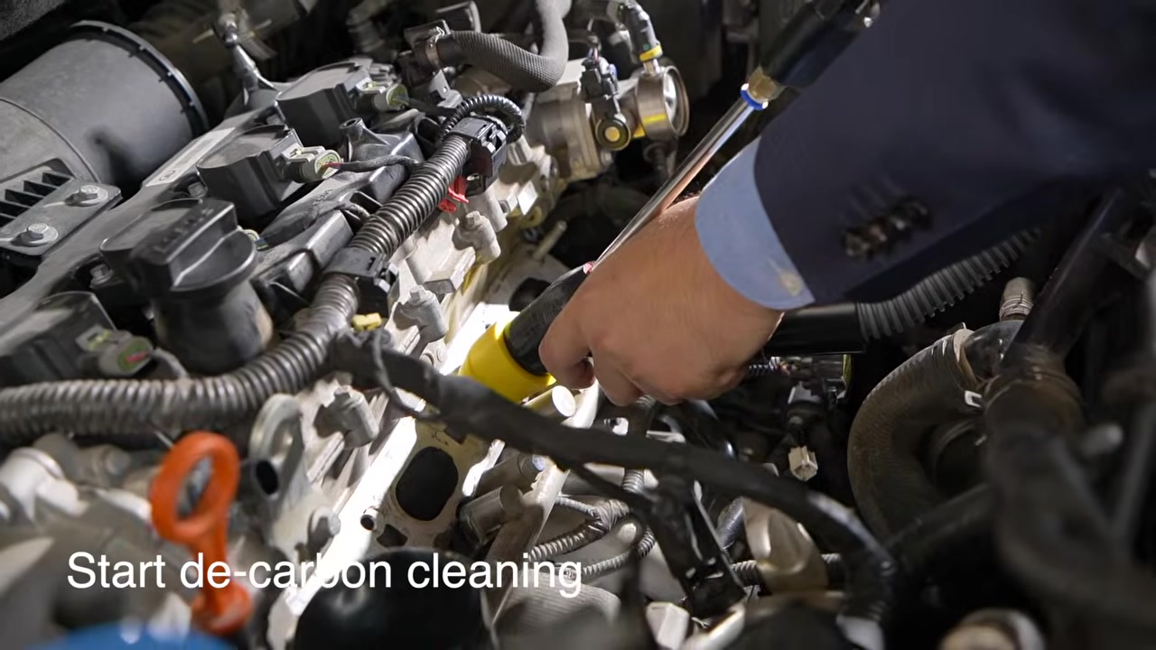
Step 9: Blast and recover in controlled passes
Start abrasive flow while maintaining the adapter seal and recovery. Sweep the nozzle across the approved port and valve surfaces rather than holding it against one point. Use short, observable passes. Release the gun before changing tube angle, adapter position, or hand support.
Stop after each pass and inspect. The manual and videos show approximate cleaning times, but deposit hardness, access, nozzle angle, air delivery, media condition, and the vehicle procedure differ. Time is not the pass condition; controlled deposit removal without surface damage or lost media is.
Stop: Stop immediately for loss of seal, visible media escape, abnormal vibration, hose collapse, unstable suction, new engine-opening exposure, nozzle contact, unexpected liquid, machine heat, smoke, odor, or sound.
Completion check: Deposits are removed to the vehicle procedure’s required condition, the underlying surface remains undamaged, and blast and recovery stayed controlled throughout.
Step 10: Recover residual media and inspect the port
Release the blasting control but keep recovery running while you sweep the nozzle and adapter area to collect loose abrasive. Then use an approved vacuum, controlled air method, lighting, and a borescope as the vehicle procedure allows. Inspect the valve pocket, runner walls, edges, gasket surface, neighboring openings, and every recess where media could remain.
Do not assume residual walnut will safely burn. Remove visible media before rotating the engine or exposing another valve. If the crank must move for the next port, first protect the completed port and confirm no loose material can be drawn into it.
Pass condition: No visible loose abrasive or carbon debris remains in the cleaned port, the valve and surface condition are documented, and the port is protected before moving on.
Step 11: Repeat one port at a time
Move to the next runner only after the previous port passes inspection. Reconfirm the new target valve fully closed; do not assume a fixed crank angle closes every remaining intake valve. Recheck adapter fit, recovery seal, nozzle clearance, filter airflow, and media condition each time.
Compare the completed ports under similar lighting. If one area does not respond, investigate access, media flow, deposit type, and whether blasting remains an approved method instead of extending the run indefinitely.
Completion check: Every serviced runner has its own valve-closure confirmation, controlled cleaning record, post-cleaning image, and residual-media pass.
Step 12: Shut down, reassemble, and validate the vehicle
Release the gun, switch recovery Off, close and depressurize the air supply, disconnect the air line, switch off power, and unplug the machine. Do not open the head while the machine is energized or the media path is pressurized.
Perform one final inspection of every engine opening. Remove protective covers in a controlled count. Install new seals where required, clean mating surfaces by the approved method, and reinstall the intake system using the specified sequence and torque. Reconnect lines, sensors, actuators, grounds, and battery connections exactly as documented.
Before returning the vehicle, check for intake, vacuum, fuel, coolant, and electrical faults as applicable. Run the required diagnostic scan, clear or adapt only where the service procedure instructs, monitor live data, and perform the approved functional or road check. Compare the result with the recorded baseline rather than promising a power or fuel-economy change.
Completion check: All media and protection are accounted for, reassembly passes leak and diagnostic checks, no new fault is present, and the service record links the outcome to the original complaint.
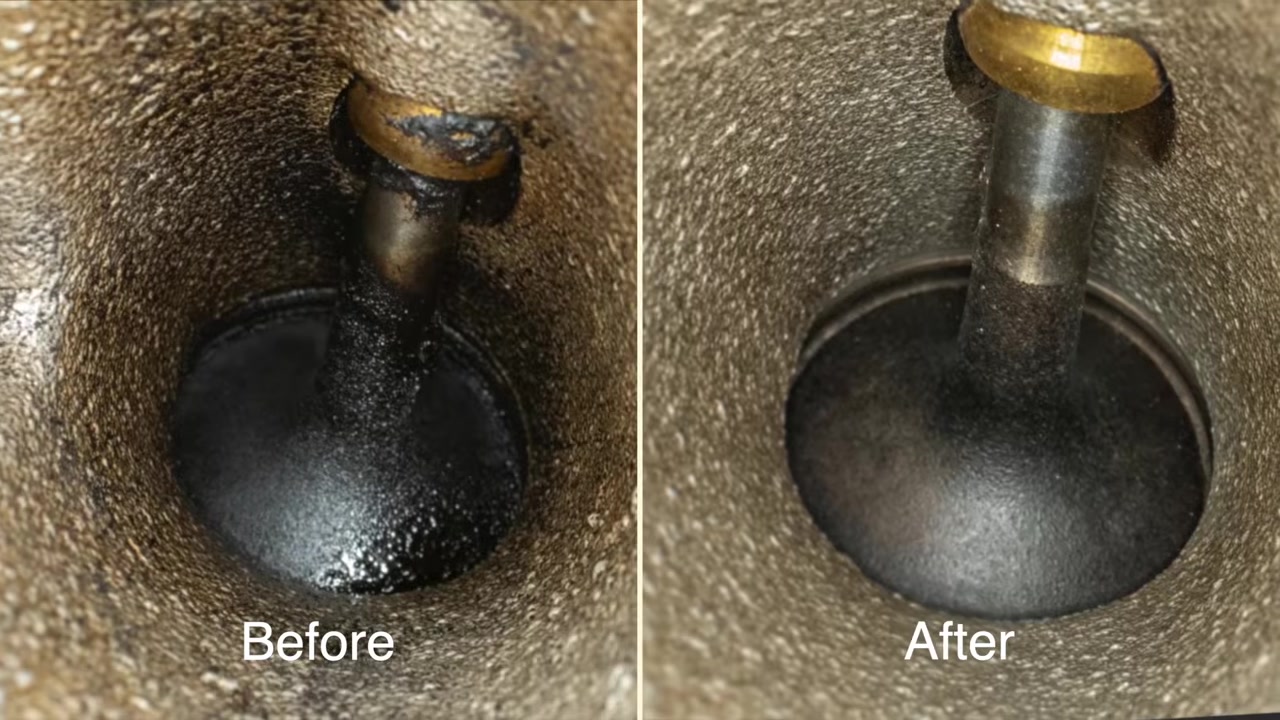
How to judge the cleaning result
Use three gates:
- Surface gate: the target deposit is removed to the specified condition without visible surface, valve, seat, guide, seal, connector, hose, or wiring damage.
- Contamination gate: no visible abrasive or loosened carbon remains in the port, neighboring openings, manifold, or engine bay.
- Vehicle gate: reassembly is leak-free and the diagnostic and functional checks meet the vehicle procedure.
A before/after image supports only the visible surface change. It does not prove valve sealing, compression, injector behavior, engine wear, or that every drivability symptom has one cause. If the symptom remains, continue diagnosis from the original baseline.
Common HTS518 mistakes
Blasting before proving the valve closed
This is the highest-risk error. Confirm the exact target valve with vehicle data and direct evidence before the adapter is sealed.
Treating a port adapter as universal
The included shapes broaden coverage but do not fit every engine. A poor seal scatters media and weakens recovery.
Copying one compressor number from a different source
Product pages, videos, compressors, hoses, media, and regional machine revisions can differ. Use the current delivered-machine instructions and workshop setup; never exceed the lowest component limit.
Reusing unknown abrasive
Recovered material can contain carbon, oil, metal, moisture, and allergens. Start with fresh dry media and handle used material according to its condition, SDS, vehicle procedure, and local rules.
Using cleaning time as the success criterion
A two- or three-minute example is not a universal recipe. Inspect after controlled passes and stop when the approved surface condition is reached.
Restarting because walnut shell is combustible
Combustibility is not a cleanup plan. Visually inspect and remove loose media before crank rotation, reassembly, or restart.
Shutdown and maintenance checklist
After each job:
- isolate pressure and power before opening the machine;
- dispose of contaminated abrasive according to the SDS and local rules;
- inspect and clean the filter without contaminating its clean side;
- clear the gun, nozzle, hoses, elbow, adapters, and couplers by the approved method;
- check latches, wheels, handle, cable, air fitting, seals, and hose walls;
- keep corrosive liquid away from the machine;
- store the HTS518 dry, unplugged, unpressurized, and protected from heat and humidity.
Never run the recovery motor without its filter. Replace damaged electrical or pressure-path parts through qualified service rather than taping, splicing, or improvising a repair.
Frequently asked questions
Does HTS518 include an air compressor?
No. Its recovery motor is built into the machine, but blasting requires a compatible external compressed-air supply.
How much walnut abrasive should I add?
The current manual recommends more than 2 kg. Use that as a starting minimum and stay within the delivered machine’s current instructions and safe bucket/filter clearance. Do not overfill.
What pressure should I use?
There is no safe universal number for every machine revision, compressor, hose, media condition, nozzle, and engine. Follow the delivered HTS518 manual and nameplate, the compressor and hose limits, the media requirement, and the vehicle procedure. Never exceed the lowest component limit.
Can HTS518 clean a combustion chamber?
This guide does not use it for combustion-chamber cleaning. HTS518 is treated here as an intake-port and intake-valve cleaner. Use only an exact-model, vehicle-approved procedure for any different application.
Can I clean without removing the intake manifold?
Only if the vehicle maker provides safe access that lets you directly confirm valve closure, seal the port, control the nozzle, recover media, and inspect the result. If those conditions cannot be met, obtain the approved access by removing the required components.
Can walnut abrasive be reused?
Do not assume it can. Recovered media may be contaminated or moisture-damaged. Follow the current manual, abrasive SDS, vehicle procedure, observed condition, and local waste rules; fresh dry media is the controlled default.
How long should one port take?
Use short cleaning-and-inspection cycles. The job is complete when the approved surface condition is reached and residual media is fully removed—not when a generic timer expires.
What must happen before engine restart?
Confirm every serviced port is free of visible media, all protective items are accounted for, new seals and fasteners are installed as required, reassembly torque is correct, and leak, scan, adaptation, and functional checks pass.
The reliable HTS518 workflow
The reliable sequence is simple to remember: diagnose, expose, prove the valve closed, protect neighboring openings, seal the correct adapter, blast and recover in short passes, inspect, remove every trace of loose media, then reassemble and validate the vehicle. The HTS518 supplies the cleaning and recovery system; the quality of the service comes from controlling the engine opening at every step.











Comments 0
Questions, fixes, and real-world diagnostic notes from readers.
Be the first to share a diagnostic result or ask a follow-up question.