
How to Use the MRCARTOOL B80 OBD2 Memory Saver

The MRCARTOOL B80 OBD2 memory saver feeds a small 12 V backup supply into a compatible vehicle through its diagnostic connector while the main battery is replaced. Its voltage and current display can confirm that the backup source is present and show changing vehicle demand. It is not a jump starter, battery charger or permission to keep vehicle loads running: the path is protected by a 3 A fast-blow fuse and must be kept quiet throughout the change.
Quick answer: Confirm the vehicle maker permits an OBD memory saver and the vehicle is a compatible 12 V system. Before connecting, open the hood and arrange access, then switch ignition and every load off, keep the key away and close or latch doors so lamps stay off. Place a fully charged 12 V backup battery securely. Connect B80 red to backup positive and black to backup negative, switch it on and verify a stable 10–14 V display. Plug the B80 into the vehicle OBD port and confirm current stays low and stable. Replace the main battery without letting either now-energized vehicle cable touch bodywork or each other. After the new battery is securely connected and its voltage is verified, switch off and unplug the B80, then remove black and red backup clamps.
In this guide
Check compatibility and limits
Read the exact MRCARTOOL B80 manual and the vehicle battery-replacement procedure before work. The manual specifies 10–14 V operation, temperature from -20°C to 60°C, a built-in 3 A fast-blow fuse and a listed operating current below 7 A. Because the actual protected OBD feed contains a 3 A fuse, plan the job around a very low sleeping load rather than treating the broader current line as usable capacity. The unit alarms below 10 V or above 14 V and shuts its output off above 16 V.
Confirm four points before proceeding: the vehicle uses a 12 V low-voltage system; the diagnostic connector has the required battery-feed path with ignition off; the manufacturer permits external memory support during this battery procedure; and no battery registration, isolation, airbag, hybrid/EV or anti-theft instruction requires a different sequence. Some vehicles intentionally need complete power removal or a manufacturer service supply. In that case, do not use the B80.
The vehicle remains electrically live after its main battery is disconnected. The B80 supplies vehicle circuits from the backup battery through the OBD connector. Treat the removed positive cable and related wiring as energized. Insulate and restrain disconnected cable ends immediately; never let them touch bodywork, tools, each other or the removed battery.
Prepare the vehicle before backup power
1. Finish every access task first
Park on a level ventilated surface, select Park or Neutral, apply the parking brake and chock the wheels. Wear eye protection and follow the battery maker’s handling rules. Open the hood, unlock required compartments and position the replacement battery, terminal tools and insulating covers before connecting the B80. If a window should remain open for access, lower it now; do not operate it after backup power is active.
2. Put the vehicle into its lowest-load state
Turn ignition off, remove or move the key/fob away as required and switch off lamps, HVAC, audio, chargers, heated equipment and accessories. Prevent courtesy, hood, trunk and door lamps from waking. Do not open a door, press a remote, turn on a light, operate a seat or start the vehicle during the replacement. The B80 product instructions warn that switching devices on can overload or damage the OBD connector. Wait for normal modules to settle according to service information.
3. Inspect both batteries and the B80
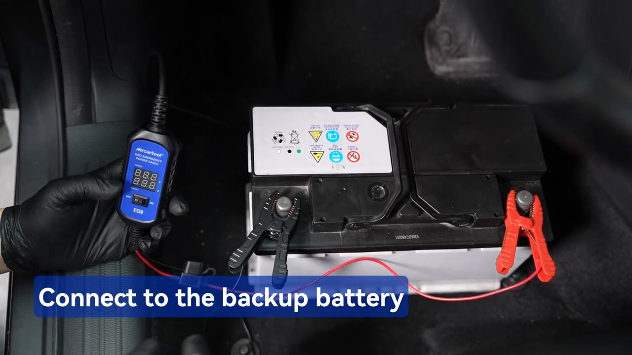
Use a fully charged, serviceable 12 V backup battery as the exact manual and official video show. Keep it upright and secured away from the removed main battery and metal tools. Do not substitute an unapproved charger, jump pack or high-voltage source; the retained B80 instructions document a spare 12 V battery. Inspect the B80 clamps, fuse holder, OBD plug, cable, switch and display. Replace a damaged cable or blown fuse only with the specified part and rating.
Connect the backup battery
4. Connect red positive, then black negative
Keep the OBD plug out of the vehicle. Attach the red B80 clamp to the backup-battery positive terminal and black to negative, exactly as the manual and official video demonstrate. Prevent the clamps from rotating or touching. Set the B80 power switch to ON if needed. Reverse-polarity protection should prevent normal energization after a reversed connection, but do not use that protection as a test—correct polarity from reliable battery markings before switching on.

5. Verify 10–14 V before touching the vehicle
Read the red voltage display with only the backup battery attached. It must be stable inside the documented 10–14 V range. A value below 10 V can fail to preserve memory; a value above 14 V is outside normal operation, and above 16 V should trigger power-off protection. Do not continue through an alarm, flashing display, heat, odor or unstable number. Correct the battery condition or connection first. Current should remain at or near zero before the OBD plug is connected.
Connect the vehicle OBD port
6. Locate and inspect the 16-pin connector
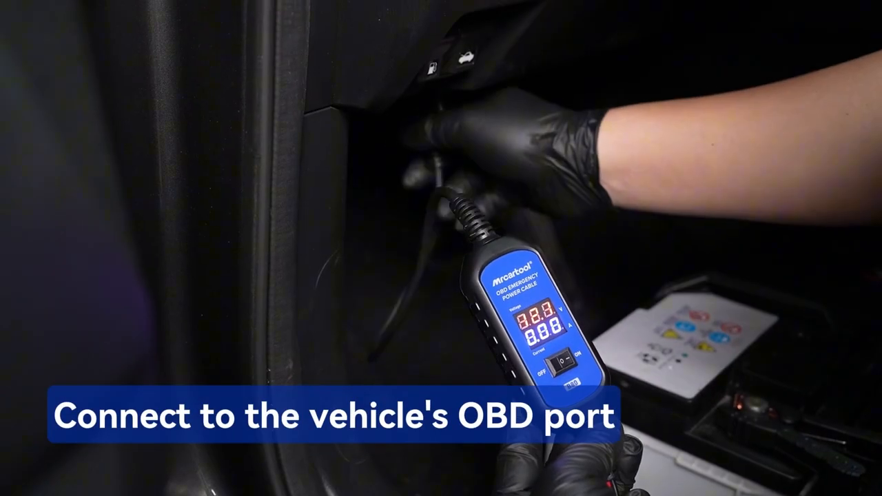
Use vehicle information to locate the diagnostic connector. Check for bent, pushed-back, corroded or modified terminals and confirm no scan tool, telematics dongle or splitter is already connected. Do not force the keyed B80 plug or hang its cable where a foot can pull it out. If the connector is loose or its power path is unknown, stop and use the manufacturer’s approved memory-support point instead.
7. Insert the OBD plug and watch both displays
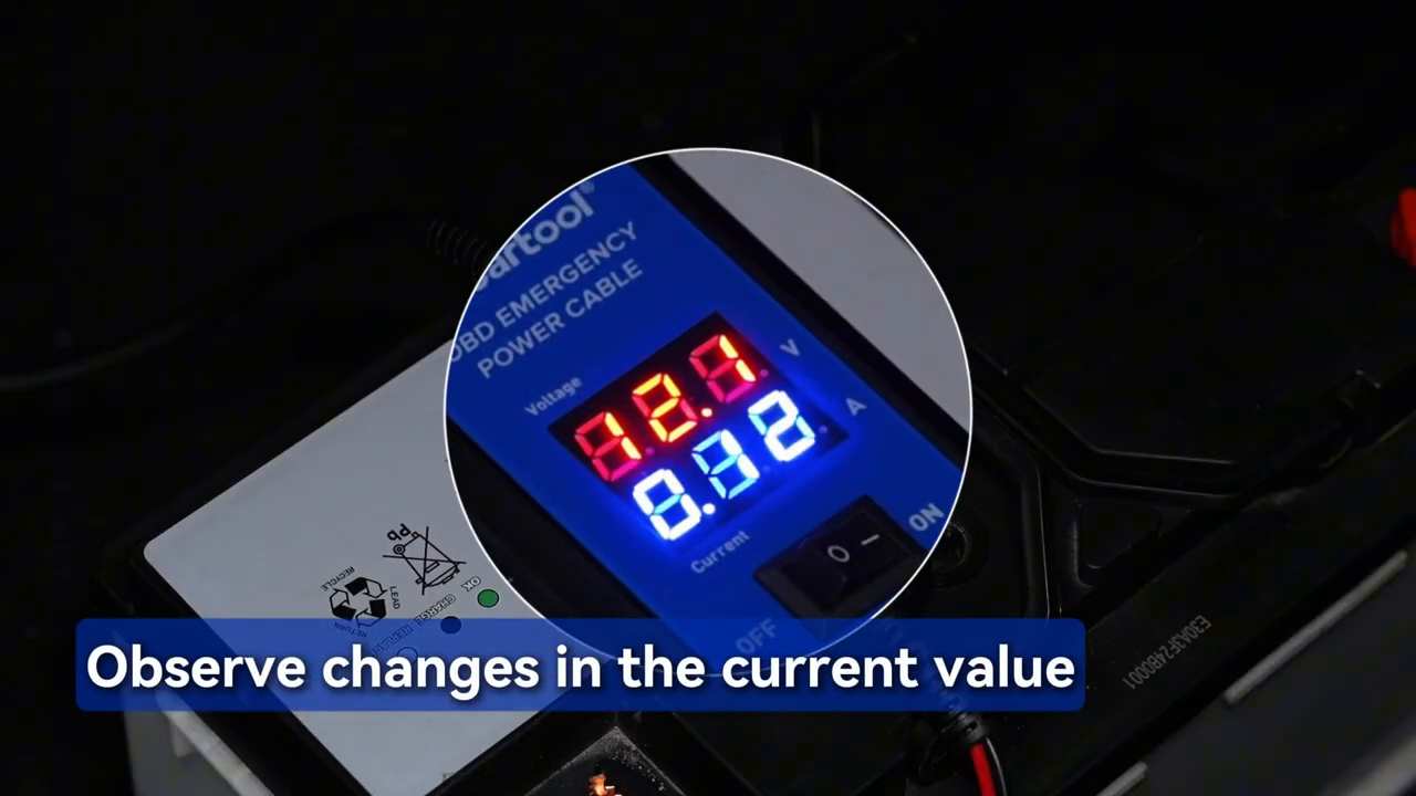
With B80 voltage already stable, insert the OBD plug fully as the official video shows. The current display should rise from its pre-connection value and then settle as the vehicle remains asleep. Confirm voltage stays inside 10–14 V, no alarm sounds and the cable, fuse holder and OBD connector remain cool. A rising or erratic load means a module or accessory is awake; do not disconnect the main battery until the cause is understood.
The manual suggests removing noncritical fuses to control current, but fuse handling can wake modules, erase adaptations or disable the wrong circuit. Do not pull fuses generically. Use that approach only when the exact vehicle procedure identifies the fuses, order and consequences. If the resting current cannot stay safely below the 3 A protected path, use a different manufacturer-approved support method.
Replace the main battery
8. Verify the support path one final time
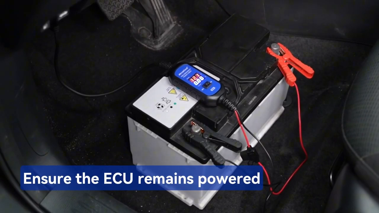
Record B80 voltage and current. Confirm clamps, OBD plug and backup battery cannot move, and make sure no person will open a door or operate a load. Have insulating terminal covers ready. The B80 maintains low-current memory only; it cannot support cranking, ignition-on diagnosis, module programming or accessory operation. Do not test the horn, lamps or starter.
9. Disconnect the old battery using the vehicle procedure
Follow the exact terminal order, vent, hold-down, sensor and battery-monitor instructions for the vehicle. A common 12 V procedure removes vehicle negative first and positive second, but service information controls. As soon as a cable is removed, cover and restrain its terminal. Because backup power is entering through OBD, the vehicle positive cable can remain electrically live even though it is off the old battery. Do not rest a wrench across a terminal and ground.
Lift the old battery with suitable handling equipment and keep it upright. Do not allow its posts to contact the supported vehicle cables. Clean or repair terminal connections only by the approved method without disturbing the B80. If the B80 alarm sounds, voltage collapses, current approaches the protection limit, the display goes blank or the OBD plug is disturbed, stop. Do not assume memory support survived; finish the battery work safely, then follow the vehicle relearn procedure if needed.
10. Install and secure the replacement battery
Confirm chemistry, capacity, terminal layout and physical fit before lowering the new battery into place. Secure the hold-down, vent and covers. Attach terminals in the order specified by the vehicle maker—often positive then negative for a conventional 12 V replacement—and torque them to specification. Reconnect any battery-monitor sensor exactly as required. Do not switch on vehicle loads yet.

Restore normal vehicle power
11. Prove the new battery is carrying the vehicle
Before removing the B80, confirm both new-battery terminals are secure and the battery voltage is plausible at the specified test points. Watch the B80 display for a stable transition and no alarm. If the current direction or value is unexpected, stop and verify battery polarity, terminal connection and the B80 path rather than unplugging blindly.
12. Remove the B80 in a controlled order
With ignition and loads still off, switch the B80 OFF, unplug it from the vehicle OBD port and protect the connector. Then remove the black backup-battery clamp followed by red, keeping them separated. This order ends the external feed before exposed backup clamps are handled. Inspect the 3 A fuse, cable and plugs for heat or damage and store the dry tool without sharply bending the cable.
13. Verify settings and complete required service
Start the vehicle only after all tools, covers and cables are clear and the manufacturer’s procedure permits it. Check clock, radio presets, windows, seats, steering-angle or idle behavior as applicable. The B80 can reduce volatile-memory loss but cannot guarantee every setting remains: individual modules, security policies and a momentary interruption can still require relearn. Perform battery registration, state-of-charge reset or diagnostic checks whenever the vehicle procedure specifies them.
Use the current display as a trend
The B80 displays current while it supports the vehicle, and the official video shows the value changing after connection. That is useful for recognizing an awakened load or a sudden increase. It is not automatically a final parasitic-draw diagnosis. Relays cycle, modules time out at different rates and opening the vehicle can restart the sleep timer. The retained instructions do not state display accuracy or resolution for a formal acceptance limit.
For leakage diagnosis, use trained-personnel procedures, the wiring diagram, a defined sleep period and a suitable calibrated current method. Do not repeatedly pull random fuses or disconnect the vehicle negative while the B80 is energizing the car. Record the baseline, change only one authorized circuit at a time and allow modules to settle before interpreting a difference. Stop before the protected path is overloaded.
Troubleshoot safely
| Symptom | What to do |
|---|---|
| No display after clamps | Switch off; verify fully charged 12 V backup battery, red/black polarity, clamp contact and 3 A fuse |
| Voltage below 10 V | Do not connect OBD; charge or replace the backup battery using its approved method |
| Voltage above 14 V or alarm | Disconnect and use a compliant 12 V source; above 16 V should trigger power-off protection |
| Current jumps after OBD connection | Keep main battery connected; find the awake load, open door, lamp, accessory or incompatible circuit |
| Display goes blank during replacement | Assume support was interrupted; finish safely and perform required vehicle relearns |
| 3 A fuse opens | Do not bypass or up-rate it; remove the overload cause and install only the specified replacement |
| OBD connector or cable warms | Stop immediately, restore normal battery power safely and inspect the connector/path |
| Settings still reset | Check vehicle compatibility, support interruption and model-specific initialization requirements |
Final B80 checklist
- Vehicle maker permits OBD memory support for this 12 V battery procedure
- Replacement battery, tools and access prepared before backup connection
- Ignition, lamps, HVAC, audio and accessories off; doors kept from waking modules
- Fully charged 12 V backup battery secured upright
- B80 cable, OBD plug, clamps, switch and 3 A fuse inspected
- Red connected to backup positive and black to negative
- Voltage stable within 10–14 V before OBD connection
- OBD plug secure and current low and stable before main-battery removal
- No doors, loads, ignition or starting operated during support
- Disconnected vehicle terminals separately insulated and restrained
- New battery fit, polarity, hold-down, vent and terminal torque verified
- New battery carrying the vehicle before B80 switch-off and removal
- B80 unplugged from OBD before backup clamps are removed
- Required battery registration, relearn and settings checks completed
A successful B80 job is intentionally uneventful. Prepare access before connecting, reduce the car to its sleeping load, prove the backup battery on the display and keep the OBD path below its fused capacity. Once support is active, every removed vehicle cable must be treated as live until the new battery is secure. Restore normal power before removing the B80, then verify both retained settings and any model-specific battery service.








Comments 0
Questions, fixes, and real-world diagnostic notes from readers.
Be the first to share a diagnostic result or ask a follow-up question.