
How to Use the MRCARTOOL B530 Automotive Circuit Tester

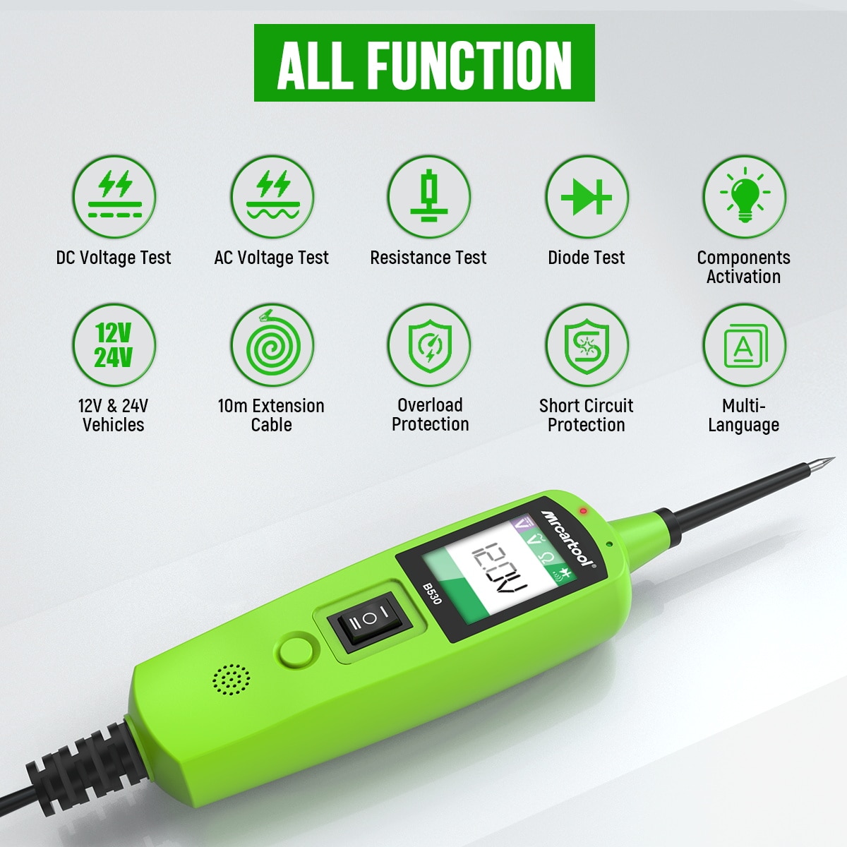
The MRCARTOOL B530 automotive circuit tester is a battery-powered probe for 12/24 V vehicle work. It can display DC voltage, show AC maximum/minimum voltage with frequency and duty cycle, measure resistance against its auxiliary ground lead, identify polarity and supply positive or negative battery potential through the probe tip. That final capability makes preparation more important than speed: measuring an identified circuit and powering an unknown circuit are completely different operations.
Quick answer: Obtain the vehicle wiring diagram and identify the circuit before connecting the B530. With ignition off, engine stopped and the work area ventilated, connect the red battery clamp to positive and black clamp to negative. Run the built-in self-test: the forward rocker position should put positive battery voltage at the probe, illuminate red and show battery voltage; the rearward position should put ground at the probe, illuminate green and show about 0.0 V. Use the Mode button to select DC voltage, AC voltage, resistance or tone. Begin with passive measurement. Never press the power rocker on an ECU, network, restraint, sensor, protected or unknown circuit. If the breaker trips, stop, find the cause, allow at least 15 seconds to cool and reset only after the fault is understood.
In this guide
Read the exact instructions first
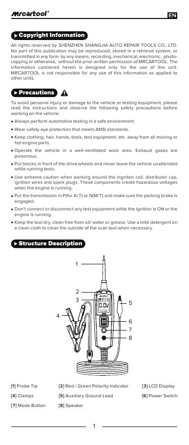
Keep the exact MRCARTOOL B530 manual available at the vehicle. Its English section identifies the probe tip, red/green polarity indicator, LCD, battery clamps, auxiliary ground lead, momentary power rocker, Mode button and speaker. The specification table names 12/24 V battery power, while the general description says 6–30 V systems and the current product page says 9–30 V. Because those bounds conflict, this guide limits normal use to the manual-listed 12/24 V vehicle systems and does not treat a numerical edge as permission.
Wear suitable eye protection. Keep hair, clothing, hands, cables and the long probe lead away from fans, belts, exhaust and hot parts. Work in ventilation, chock the wheels, select Park or Neutral and apply the parking brake. The manual specifically warns not to connect or disconnect test equipment with ignition on or the engine running, and calls out hazardous ignition-system voltage. Hybrid, EV, airbag, pyrotechnic and high-voltage circuits require their own isolation procedures and are outside this general guide.
The rocker switch is not a measurement selector. Pressing it deliberately applies battery positive or battery negative to the probe tip. Do not press it merely to see what happens. Random voltage or ground can destroy control modules, deploy restraints, move actuators, overheat wiring or blow vehicle protection. Use it only when the vehicle schematic and component procedure explicitly permit an external powered test.
Plan the test before touching the circuit
Write down the symptom, circuit name, expected voltage or waveform, connector pins, ground path and safe test state. Decide whether the circuit must be energized, asleep or disconnected. Check whether probing from the back of a connector is approved; piercing insulation can admit moisture and create a future corrosion point, so avoid it unless the repair procedure allows it and the puncture will be sealed correctly. Keep the B530 tip covered until the target is identified.
The 10 m cable makes front-to-rear checks practical, but it also creates a routing hazard. Lay it along a protected path, not across a walkway, door latch, fan, belt, exhaust, wheel or pedal. Do not allow a battery clamp to touch bodywork or another terminal. Keep a suitable fire extinguisher available whenever electrical work occurs near fuel or chemicals, as the product and manual safety notes require.
Connect and self-test the B530
1. Inspect the tester and vehicle
Check the probe, insulation, clamps, auxiliary lead, display, speaker and cable for cuts, looseness, contamination or heat damage. Confirm the vehicle battery is not leaking, frozen, swollen or mechanically damaged. Identify positive and negative terminals from reliable markings and vehicle information; never infer polarity from cable color alone. Turn the ignition off, remove loads as required and keep the engine stopped while attaching the tester.
2. Connect red positive, then black negative
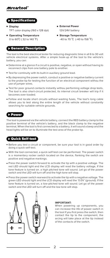
The manual directs red to the vehicle-battery positive terminal and black to negative. Make each clamp contact clean metal and prevent it from rotating. When first connected, the B530 should beep and illuminate the probe area. If polarity is uncertain, the display is abnormal, a clamp arcs excessively or the cable warms, disconnect safely and correct the setup before proceeding. Do not hold the exposed tip where it can contact ground.
3. Run the positive and negative self-test
Keep the probe clear of the vehicle. Briefly press the momentary rocker forward. The manual says the red LED should illuminate, the screen should show battery voltage and an enabled tone should sound high; release it immediately. Then briefly press the rocker rearward. The green LED should illuminate, the screen should show about 0.0 V and the tone should be low; release it. A missing LED, implausible value, stuck rocker or unexpected breaker trip means the tester is not ready.
Use the four work modes
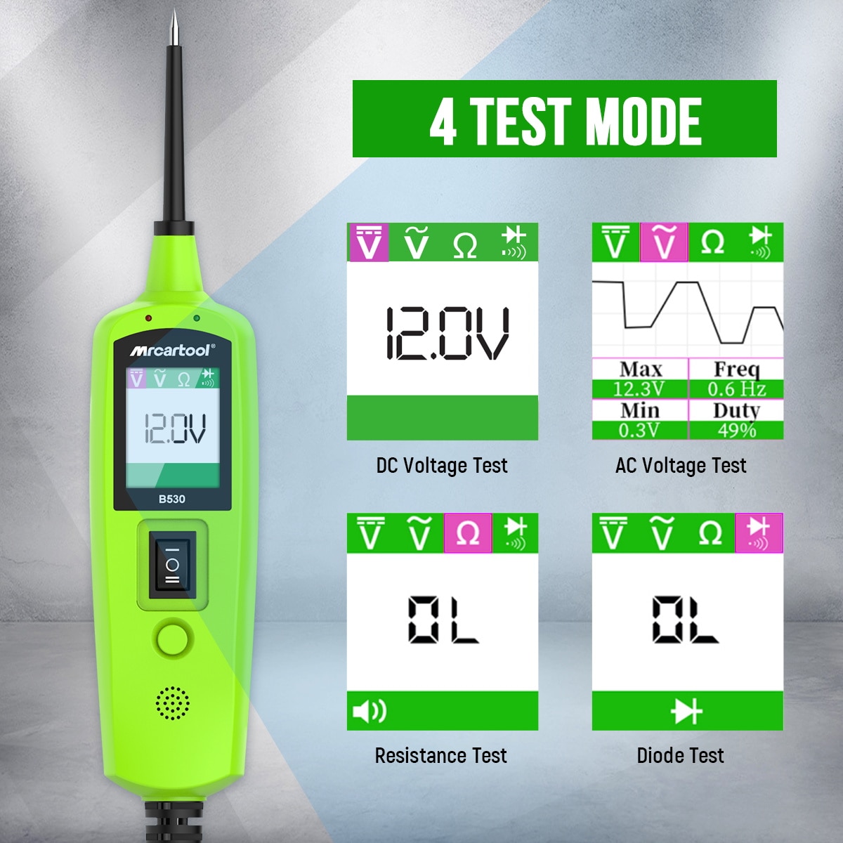
The Mode button cycles through DC Voltage, AC Voltage, Resistance and Tone On/Off. Confirm the screen symbol and unit before making contact. A wrong mode can produce a believable but meaningless number. The product gallery also advertises a diode test; the retained English manual describes the four-mode sequence above and does not provide a separate English diode procedure, so this tutorial does not invent one. Use only the exact screen and instructions on the unit in hand.
4. Measure DC voltage
Select DC Voltage, connect the tester reference through its battery clamps and touch the probe to the identified test point without pressing the rocker. The manual specifies 0.1 V display resolution. Compare the reading with the expected circuit state and battery voltage measured under the same conditions. A voltage reading does not prove the circuit can carry load; use the manufacturer voltage-drop or loaded-circuit procedure when required.
5. Observe AC or pulsed activity
In AC Voltage mode, the B530 displays maximum voltage, minimum voltage, frequency and duty cycle. This can reveal whether a suitable low-voltage automotive signal changes, but it is not a substitute for a waveform scope. Confirm the circuit is appropriate for this tool, use the specified reference and compare against service information. Do not use the probe on ignition secondary, mains voltage, high-voltage traction systems or signals that require a high-impedance or isolated instrument.
6. Measure resistance and continuity
Select Resistance and use the probe with chassis ground or the auxiliary ground lead as the manual describes. Remove external power from the path unless the exact procedure explicitly establishes a safe state; never inject power while reading resistance. A near-zero value and green indication can support continuity, while another value shows resistance. Continuity alone does not prove a connection will carry operational current, and a parallel path through modules can mislead the reading. Disconnect and isolate components when the vehicle procedure requires it.
7. Set the audible indication
In the tone setting, the manual describes a quick Mode-button press: a short high-pitched sound means audio on and a short low beep means audio off. Use audio when the display cannot stay in view, but continue to verify the numerical reading and circuit state. Turn it off for long monitoring when repeated sound distracts the technician. Never use sound alone to identify a safety-critical conductor.
Interpret polarity correctly
In DC mode, a positive circuit produces the red indication and an enabled high tone; a negative circuit produces green and a low tone; an open circuit produces neither. The manual adds an important tolerance: red or green indication occurs when probe voltage is within about ±0.8 V of battery voltage or ground. A numerical voltage can still appear without either LED, which may indicate a voltage drop or simply a circuit at an intermediate voltage. Record the number—do not force it into a red/green conclusion.
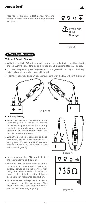
To compare with battery voltage, the manual says to keep the tip off the circuit and briefly press the rocker forward so the supply voltage appears. Record that reference, release the switch, then return to passive probing. For formal voltage-drop diagnosis, follow the vehicle maker’s loaded test across the relevant connection. The B530 shortcut can flag a difference but does not replace correct test points, load and acceptance limits.
Power a component only when authorized
Component activation is an advanced function. First isolate the component as directed, identify its current demand and polarity, and confirm it does not contain sensitive electronics. The manual excludes very high-current components such as starter motors and warns that arbitrary voltage can damage vehicle electronics. Never inject power into ECU pins, CAN/LIN wiring, sensor signal or reference lines, restraint circuits, protected outputs or any conductor that has not been positively identified.
For a permitted bench component, the exact manual uses the auxiliary ground lead on the component’s negative side, the probe at its positive terminal and the forward rocker to provide positive battery potential. It instructs the operator to observe the polarity change and breaker behavior before proceeding. Use a current-limited supply or manufacturer-specified test equipment instead whenever the procedure calls for one; the B530 does not display injected current.
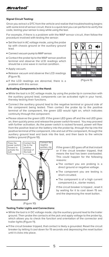
Applying ground with the rearward rocker is equally consequential. The manual warns that grounding a protected circuit can blow a vehicle fuse or trip protection. Treat a circuit breaker trip as a stop signal, not as normal confirmation to repeat. Trailer-light and in-vehicle activation examples in the manual are valid only after connector orientation, ground, circuit protection and absence of electronic drivers have been verified from the correct schematic.
Respond to the circuit breaker
When overloaded, the internal breaker opens the power-injection path. The LCD can continue measuring voltage, but pressing the rocker will no longer conduct battery current to the tip. Remove the probe from the circuit and release the rocker. Determine whether the point is direct ground, direct positive, shorted, protected or connected to a high-current load. The English manual says to allow the breaker to cool for 15 seconds and then press reset until it clicks. Reset only after the cause is removed.
The manual mentions intentionally opening the breaker as protection against accidental rocker operation. Do not use repeated breaker trips as a current-measurement method: no trip-current rating or current display is provided in the retained evidence. If current matters, use a correctly rated fused ammeter or current clamp and the vehicle procedure. Repeated trips, heat, odor, discoloration or failure to reset require the tester to be removed from service.
Troubleshoot unexpected results
| Symptom | Check first |
|---|---|
| No startup beep or light | Battery condition, red/black clamp polarity, clean contact and cable damage |
| Self-test positive is wrong | Clamp connection, supply voltage, rocker release and tester condition |
| Voltage appears but no LED | Reading may be more than ±0.8 V from battery positive or ground |
| Resistance seems too low | Parallel paths, external power, wrong reference or component not isolated |
| AC values are unstable | Wrong circuit, poor reference, changing operating state or need for an oscilloscope |
| Breaker trips immediately | Stop: direct opposite polarity, short, protected or high-current circuit |
| Breaker will not reset | Remove load, cool at least 15 seconds, inspect heat/damage and do not force reset |
| Long-cable readings vary | Battery clamps, auxiliary ground, cable routing and contact pressure |
Disconnect and store
Finish with the ignition off and engine stopped. Remove the probe from the circuit, release the rocker and leave the tip protected. Disconnect the black negative clamp, then the red positive clamp, while preventing either from contacting bodywork or each other. Inspect the lead for heat or damage, wipe the dry tool with a mild-cleaner cloth as the manual permits and coil the cable without tight bends. Store it dry in the case.
Final B530 checklist
- Vehicle schematic, expected values and safe test state identified
- Eye protection, ventilation, wheel restraint and parking brake in place
- Probe, cable, clamps, auxiliary lead and rocker inspected
- Red clamp on battery positive and black clamp on negative
- Positive and negative self-test completed away from the circuit
- DC, AC, resistance or tone mode confirmed on screen
- Passive measurement performed before any powered test
- Resistance path de-energized and isolated as required
- Power rocker never used on unknown or protected electronics
- Component polarity and current demand verified before activation
- Breaker trip cause removed before the 15-second cool/reset step
- Numeric reading checked instead of relying on LED or tone alone
- Probe removed and ignition off before clamp disconnection
- Tester inspected, cleaned dry and stored with tip protected
The B530 can shorten electrical diagnosis when its most powerful feature is also its most controlled. Connect correctly, prove the tester with the self-test, select the measurement mode deliberately and interpret numbers against the circuit diagram. Keep the rocker untouched during ordinary probing. When a powered test is genuinely required, identify the load and protection first—and treat any breaker trip as new diagnostic evidence, not an invitation to keep trying.




Comments 0
Questions, fixes, and real-world diagnostic notes from readers.
Be the first to share a diagnostic result or ask a follow-up question.