
How to Use the AUTOOL CT60 Fuel Injector Signal Generator

The AUTOOL CT60 fuel injector signal generator supplies adjustable electrical pulses to a compatible injector. It does not supply a safe fluid circuit, pressure control, spray containment, or measured flow data by itself. Use it only with the injector safely removed, firmly mounted in suitable off-vehicle equipment, and electrically identified before you select a mode.
The normal sequence is straightforward: verify the injector and test setup, connect everything while output is stopped, power the CT60 through the supplied marked path, select the verified injector mode, set working time and simulated RPM, press Start/Pause, make a limited observation, then stop and de-energize the setup before disconnecting anything.
Last reviewed: August 28, 2026.
In this guide
What the CT60 provides—and what it does not
The CT60 provides the pulse-control part of an injector bench setup:
- standard-injector and compatible high-voltage operating modes;
- an LCD showing working time and simulated RPM;
- separate
TIME +/−andRPM +/−controls; - a
SELECTcontrol for injector mode; - a
START/PAUSEcontrol and status indicators; - a documented setting range of 0–99 minutes and 600–4000 simulated RPM;
- simultaneous output for two compatible injectors when the rest of the setup safely supports it.
The complete setup still needs everything the CT60 does not provide: a stable injector fixture, the correct adapter, any permitted test or cleaning liquid, controlled pressure, full spray containment, and—if you need a measured result—appropriate flow or leakage measurement. Power the CT60 itself only through the supplied, matching, clearly marked power path.
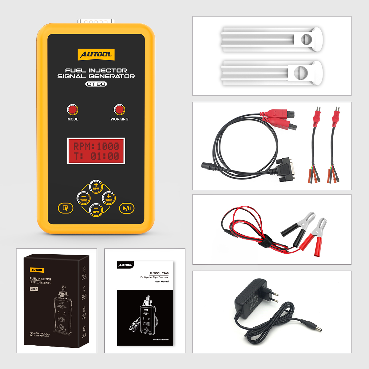
Do not hold an injector in your hand while pulsing it. Do not improvise an open container, aerosol-can rig, hose, power lead, or pressure vessel. If your separate equipment does not keep the injector secure and any permitted spray fully controlled, do not start.
Before you connect anything
Continue only when all of these conditions are true:
- The engine is off, the fuel system has been made safe under the vehicle maker’s procedure, and the injector is already removed.
- You have identified the exact injector part number or electrical requirements. You are not choosing a mode from the vehicle’s turbocharger or engine type.
- The connector fits without forcing and the injector’s required drive type is supported by the CT60 mode you intend to use.
- The injector is secured in suitable off-vehicle equipment. It cannot twist, lift, point toward a person, or discharge outside the equipment’s guarded collection area.
- Any liquid, pressure source, adapter, seal, and fixture is approved for the injector and is being used under its own instructions.
- CT60 cables, connectors, adapter and case are dry and undamaged.
- The delivered power adapter and cable labels give you one unambiguous connection path.
- The work area is ventilated and free from smoking, flame, hot work, hot engine parts, and unnecessary spark sources. You are wearing suitable eye protection.
Stop before setup if the injector type, connector, power path, fluid, pressure method, or containment is uncertain. The CT60’s two mode names are not a substitute for injector or vehicle service data.
Know the CT60 controls
The front panel groups all operating controls around the display. SELECT changes the injector mode. The TIME +/− keys set the working timer. The RPM +/− keys set the simulated-speed value. START/PAUSE controls pulse output. Type and working indicators show the selected state, while the DP15 connector joins the unit to its supplied harness.
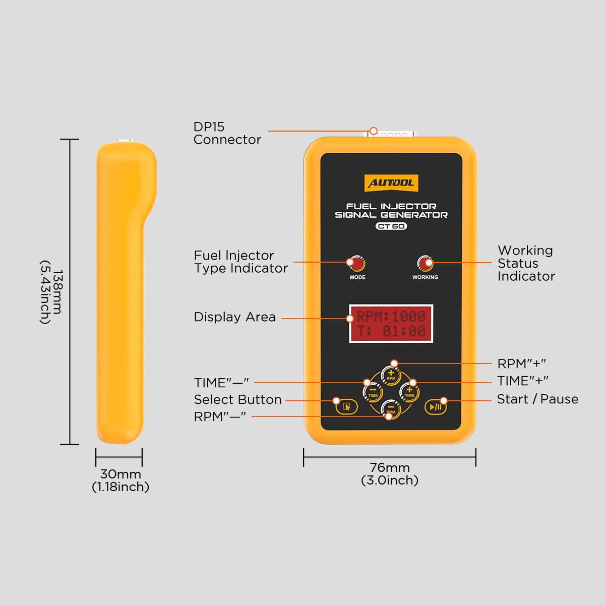
If the names, connector, display, or cable markings on your unit differ, stop and use the instructions supplied with that unit. Do not translate a similar connector shape into an assumed electrical match.
Step-by-step CT60 operating procedure
Step 1: Identify the injector and required mode
Record the injector part number and obtain its current electrical/service information. Determine whether the exact injector belongs on the CT60 standard mode or is explicitly compatible with its high-voltage mode. Also confirm that the available adapter fits and that the rest of the bench supports that injector.
Do not use “naturally aspirated” or “turbocharged” as your selection rule. Engine aspiration does not reliably identify the injector’s electrical drive requirements.
Completion check: The injector identity, required drive type, connector and fixture compatibility are all known. If any one is unknown, do not energize it.
Step 2: Build the controlled off-vehicle setup
With all power and pressure off, install the injector in the separate fixture or test equipment according to that equipment’s instructions. Seat every seal squarely, secure the injector against movement, and aim the outlet only into the equipment’s intended containment area.
If the task involves liquid, use only the liquid and pressure method approved for that equipment and injector. The CT60 controls the pulse signal; it does not make an improvised fluid arrangement safe.
Completion check: The injector is mechanically stable, connections are dry, and any possible discharge remains fully inside the intended collection or measurement area.
Stop: Do not proceed with a cut or swollen seal, loose adapter, damaged injector body, unguarded outlet, leaking fitting, or an injector that can move when the harness is touched.
Step 3: Inspect the CT60 and supplied parts
Keep the CT60 de-energized. Inspect the case, DP15 connection, signal harness, adapter leads, power adapter and any clamp lead included with your version. Look for bent contacts, exposed conductor, crushed insulation, contamination, loose housings, heat damage or an unreadable electrical label.
Use only the matching supplied parts in the arrangement marked for your delivered unit. The package may include several connector families; their presence does not mean that all of them are valid for your injector.
Completion check: Every part in the intended path is clean, dry, undamaged, correctly marked and strain-free.
Step 4: Connect the CT60 harness while output is off
Confirm that the CT60 is not powered and that no separate bench output is active. Align the unit harness with the CT60 connector without twisting the pins, seat it fully, and secure it using the connector’s intended retention method. Route the cable away from liquid, hot surfaces, sharp edges and anything that could pull it loose.
Do not connect clamp leads to 110/220 V AC mains. If the supplied adapter, clamp lead and harness arrangement is not completely clear from the markings and the instructions delivered with your unit, stop and obtain the correct unit-specific connection information.
Completion check: The device connector is fully seated, the cable has slack, and no supply is energized.
Step 5: Connect the matching injector adapter
Select only the adapter confirmed for the exact injector. Align the keyed connectors, press them together by their housings, and verify that any latch is engaged. Do not pull or push on the wires, force a near-fitting plug, bridge terminals, or leave bare conductors exposed.
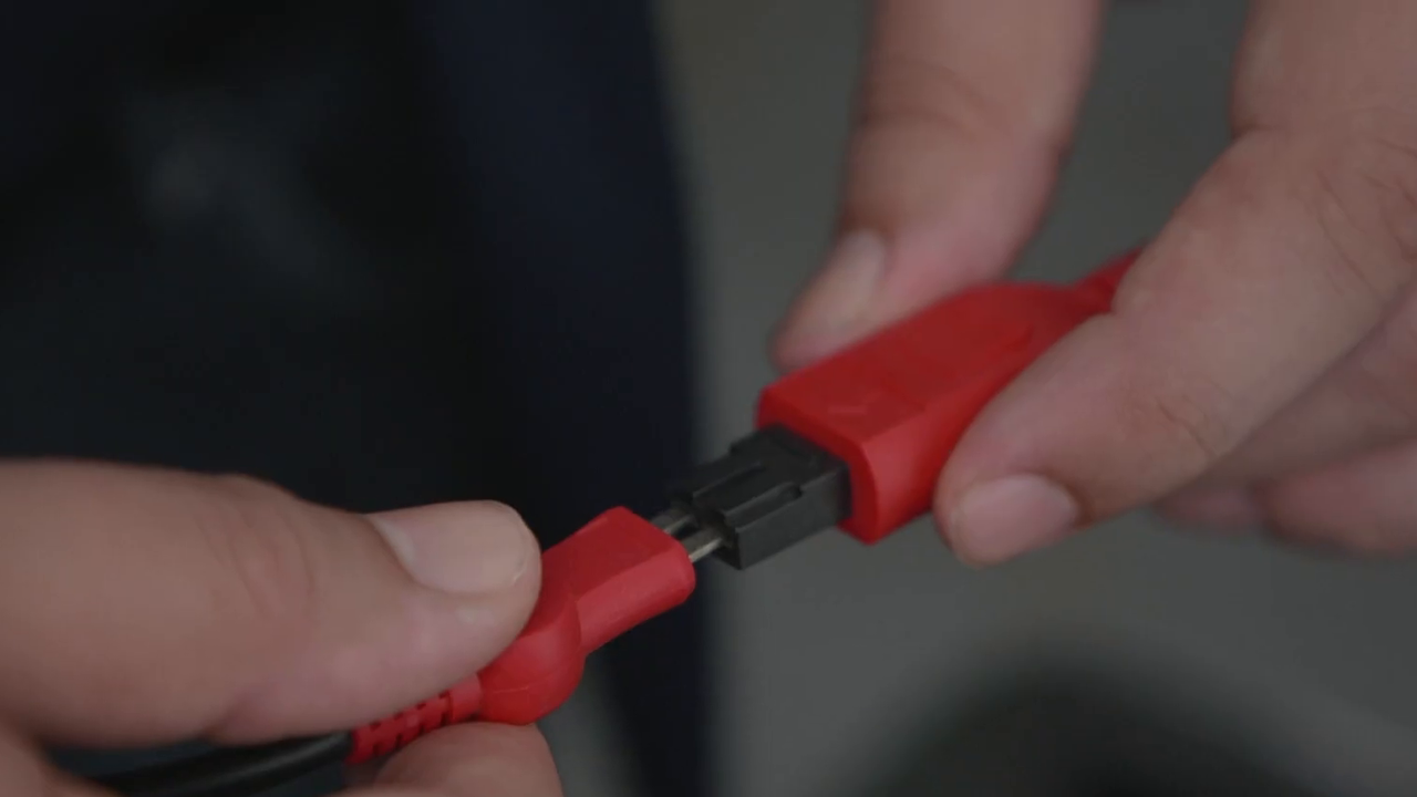
Completion check: The connection is fully seated, dry, mechanically supported and not loading the injector sideways.
Step 6: Power the CT60 through the supplied marked path
Recheck the input marking on the delivered adapter and CT60. Connect only the supplied, matching power parts in their intended order, then energize the unit. The display and indicators should start normally without flicker, odor, unexpected heat or movement at a connector.
Do not guess polarity, substitute an unverified adapter, or infer that a clamp cable belongs on a particular source from its color alone.
Completion check: The display is stable and every lead remains cool, dry and firmly seated.
Stop: Pause output if possible, then isolate the supply at a safe upstream point if the display behaves abnormally or a lead, adapter, injector connection or case becomes loose, hot, damaged, smoky or unusual. Do not handle a hot or damaged connector to disconnect it.
Step 7: Select the verified injector mode
Use SELECT to move between the displayed standard and high-voltage modes. Stop on the mode supported by the exact injector information you verified in Step 1. Read the indicator and screen—do not rely on memory or the last setting used.
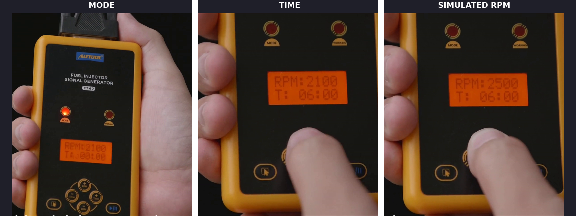
Completion check: The displayed mode matches the injector’s verified drive requirement.
Stop: If the injector information and CT60 wording do not give an exact match, do not “try the lower mode first” or pulse briefly to find out.
Step 8: Set the working time
Use TIME +/− to enter the duration required by the injector and separate test-equipment procedure. The CT60 can display settings from 0 to 99 minutes, but that available range is not a universal safe duration.
Choose only a value supported by the exact setup. If no current instruction specifies a duration or controlled method, stop rather than inventing one.
Completion check: The displayed time is deliberate, recorded and supported by the applicable equipment information.
Step 9: Set the simulated RPM
Use RPM +/− to set the required pulse-frequency simulation. The CT60’s documented display range is 600–4000 RPM. This is a command setting used to vary injector pulsing; it is not a measurement of engine speed.
Keep the value recorded whenever you compare two injectors or repeat a check. Changing time and RPM together makes a comparison harder to interpret.
Completion check: The displayed RPM setting is supported by the intended bench procedure and recorded with the selected mode and time.
Step 10: Perform a final safety scan
Before starting output, check the whole setup from power source to injector:
- The verified mode is displayed.
- Time and simulated RPM are recorded.
- The injector is locked in the fixture and cannot point toward a person.
- Every adapter, seal and fluid connection is secure.
- Any permitted spray will remain inside the intended guarded collection area.
- Cables and the CT60 are dry, cool and clear of moving or hot parts.
- You can reach
START/PAUSEand remove power without crossing the discharge area.
If another piece of equipment supplies pressure or liquid, bring it to its ready state only under that equipment’s instructions. Do not start CT60 output to check whether an incomplete setup will hold.
Step 11: Start, pause and observe
Stand clear of the injector outlet and press START/PAUSE. Watch the CT60 status and the complete contained setup. For a simple response check, record whether the injector responds consistently at the chosen setting. For a matched two-injector setup, record only visible relative behavior under the same mode, simulated RPM, time, connector arrangement, pressure and liquid conditions.
Pause output immediately if the injector shifts, liquid escapes containment, a connection loosens, the display becomes unstable, injector response becomes irregular, or any component becomes hot or damaged. Remove power if pausing does not put the setup into a clearly safe state.
One visible response cannot prove that an injector is clean, has correct flow, seals at pressure, or caused the vehicle symptom. Use a proper measured bench and the injector/vehicle specifications when you need leakage, flow, balance or diagnostic conclusions.
Completion check: The run ends normally, the result is recorded with all settings, and nothing leaked, moved, overheated or escaped containment.
Step 12: Stop, de-energize and disconnect
Pause or stop CT60 output, return any separate pressure or liquid equipment to its safe state under its own instructions, then switch off and disconnect the power source. Wait until the injector and fixture are unpressurized and safe to handle.
Disconnect by the connector housings rather than the wires. Wipe contamination using materials approved for the liquid, inspect the leads and seals again, and store the CT60 and adapters dry and protected from impact.
Completion check: Pulse output is off, power is removed, no pressure or liquid hazard remains, and all parts are clean, dry and accounted for.
Comparing two injectors without overreading the result
The CT60 can drive two compatible injectors together, but the comparison is useful only if both sides are equivalent. Use injectors with known matching requirements, the same safe fixture arrangement, matching connectors, identical pressure and liquid conditions, and the same mode, simulated RPM and time.
A visible difference tells you to investigate; it does not tell you why the difference exists. Swap positions or channels only when the separate equipment’s instructions allow it. If the difference follows the injector under the same conditions, the injector deserves further measured testing. If it remains with one side of the setup, inspect that connector, adapter, seal, pressure path and fixture before judging the injector.
CT60 troubleshooting and stop rules
| What you see | What to check while output is stopped | Do not do |
|---|---|---|
| No display | Supplied adapter markings, fully seated device connector and approved supply availability | Substitute an unverified power adapter or guess clamp polarity |
| Mode is unclear | Exact injector part number, injector/OEM data and delivered CT60 instructions | Choose from turbo/non-turbo engine type |
| Injector does not respond | Verified mode, exact adapter, connector seating and serviceable wiring | Jump the injector directly or change to high-voltage mode as a trial |
| Lead, adapter or injector becomes warm or unstable | Disconnect safely and inspect for damage, mismatch or loose contact | Continue for a shorter time and assume the problem is solved |
| Liquid leaks or spray leaves containment | Stop pulse output and make the separate fixture/pressure system safe | Hold the injector or fitting in place by hand |
| Two injectors look different | Repeat only under identical controlled conditions and use measured equipment if needed | Declare one injector failed from appearance alone |
Keep the CT60 out of service after smoke, damaged insulation, overheated connectors, liquid intrusion, a loose internal part or repeated abnormal display behavior.
Frequently asked questions
Does the CT60 clean fuel injectors by itself?
No. CT60 supplies an injector control signal. A suitable separate fixture or cleaning/test system must provide safe mounting, any approved liquid and pressure, containment, and measurement.
Does a turbocharged engine automatically require high-voltage mode?
No. Select the mode from the exact injector’s electrical requirements and current service information, not from engine aspiration.
Can I use CT60 with GDI, diesel or piezo injectors?
Do not decide from the category name alone. Continue only if the exact injector, connector and drive requirement are explicitly compatible with your CT60 version and complete bench setup. Otherwise use equipment approved for that injector family.
What time and RPM should I set?
Use values specified for the exact injector and separate test procedure. CT60 offers a 0–99 minute timer and a 600–4000 simulated-RPM range, but neither range creates one universal setting.
Can CT60 run two injectors at once?
Yes, when both injectors and the complete setup are compatible and equivalent. Treat the result as a side-by-side observation unless a proper bench supplies calibrated measurement.
Where is the CT60 manual?
Use the instructions supplied with your CT60 and match them to the unit, adapter and power labels in front of you. If the exact instructions are missing or the delivered power path is unclear, pause setup and obtain the correct unit-specific document before use.
Can I pulse an injector while it is still installed on the vehicle?
This procedure is for a safely removed injector in controlled off-vehicle equipment. Do not adapt it to an installed or pressurized vehicle fuel system.
A successful CT60 session is controlled and traceable
The useful result is not simply that an injector moved or sprayed. A successful session keeps the injector securely contained, uses a verified connector and mode, records time and simulated RPM, completes the run without heat, leakage or unstable wiring, and limits the conclusion to what the setup can actually show.
If compatibility, power routing, mounting, liquid control or the meaning of the result remains uncertain, stop there. Confirming the setup—or moving the injector to a proper measured bench—is the correct next step.


Comments 0
Questions, fixes, and real-world diagnostic notes from readers.
Be the first to share a diagnostic result or ask a follow-up question.