
How to Use the AUTOOL DM301 Automotive Diagnostic Multimeter

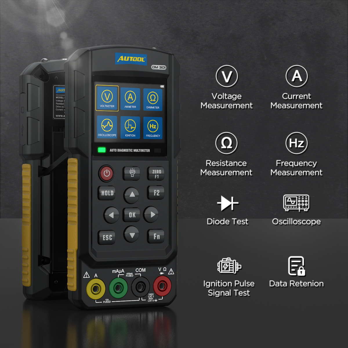
The AUTOOL DM301 is an automotive diagnostic multimeter. This guide turns the current model-specific controls and official operating sequence into a practical start-to-finish workflow.
Quick answer: Install one permitted battery setup, inspect the DM301 and its leads, identify the circuit category and expected value, then select the function and ports before contact. Measure voltage in parallel, current in series after powering the circuit down for connection, and resistance only on a de-energized, discharged circuit. Record the units and vehicle state before disconnecting safely.
In this guide
Before you start
Begin with the wiring diagram and vehicle test procedure, not with a spare probe. Identify the exact nodes, expected range and whether the test requires an energized circuit. Keep damaged leads, wet work areas and unapproved high-voltage systems outside the job; current-mode mistakes can create a direct short.
- install four matched 1.5V dry cells or a confirmed compatible rechargeable setup with correct polarity; never mix battery types or charge dry cells;
- inspect the DM301 housing, screen, input ports, interfaces, probes and insulation before power;
- identify the circuit category, maximum possible voltage or current, expected waveform and vehicle test point;
- choose voltage, current, resistance/diode, frequency, oscilloscope or a documented automotive mode before connecting;
- place the leads in the exact ports for that function and keep fingers behind the probe guards; and
- plan the safe circuit state for connecting, measuring, disconnecting and restoring every opened connection.
Use the AUTOOL manual download center to locate the current instructions when a manual is available. The delivered model label and current vehicle service information control if an older image or remembered setting differs.
DM301 controls and specifications
| Specification or function | Current model |
|---|---|
| Resistance Measurement Range | 0-1MΩ |
| Voltage Measurement Range | DC 0-1000V, AC 0-700V |
| Current Measurement Range | 0-200mA; high-current mode up to 20A |
| Frequency Measurement Range | 1Hz-1MHz |
| Oscilloscope | Single channel, 500kHz bandwidth |
| Scope Update Rate | 1mS |
| Power Supply | Dry battery / Type-C / optional lithium battery |
| Battery Notice | Batteries are not included. Dry batteries cannot be charged through the device. |
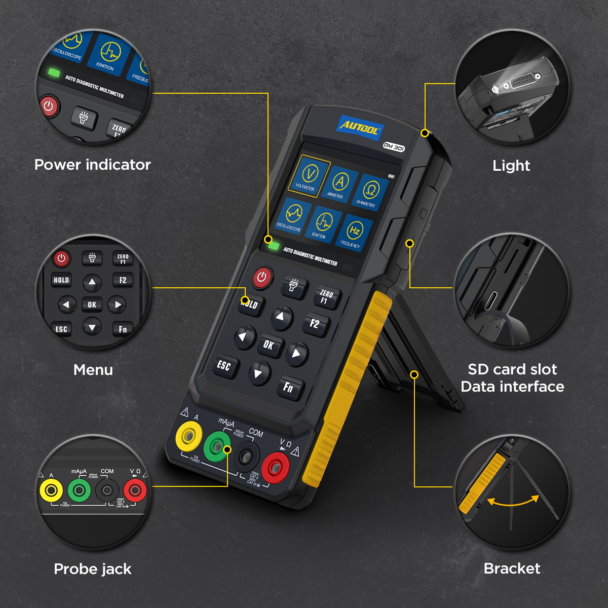
| Data Interface | SD card slot / data interface |
| Software Upgrade | Application software update by SD card |
A 1000V display range does not authorize work on every 1000V system. The meter, leads, measurement category and vehicle procedure must all permit the job. For current, use the correct mA/μA or A port, connect in series with circuit power off, and respect the continuous-current and fuse limits stated for the exact model.
How to use the DM301
Step 1: Install one permitted battery setup
The unit is shipped without batteries. Install four matched 1.5V dry cells or a confirmed compatible rechargeable lithium setup as allowed for the exact model, observing polarity and connector fit. Never mix battery types and never charge dry cells through the instrument.
Before moving on, confirm the battery type and polarity; dry cells must never be charged through the instrument.
Step 2: Inspect the meter, ports and test leads
Check the enclosure, insulation, probes and interfaces for damage. Confirm the circuit category, maximum voltage or current, expected signal and vehicle test point before choosing a port; keep away from hybrid or EV high-voltage systems unless the meter, leads and procedure are explicitly rated for that task.
Step 3: Choose the measurement and connect the correct ports
For voltage, frequency or oscilloscope work, place black in COM and red in V. For resistance or diode testing, use COM and Ω on a de-energized, discharged circuit. For current, switch circuit power off first, choose mA/μA or A from the expected current, and insert the meter in series—not across the source.
Step 4: Power on and select the exact function
Use the direction keys and OK to enter voltage, current, resistance/diode, frequency, oscilloscope or the required model-specific function. Confirm DC or AC, port prompt and displayed range before contacting the test point.
Step 5: Verify zero and the setup before the live measurement
With the probes in the correct safe condition, check the display and use the documented zero function when required. Confirm a known ground or source where appropriate; a reading from the wrong port or mode can look plausible.
Step 6: Connect without bridging adjacent conductors
Place the black reference and red probe only on the identified points, keeping fingers behind the guards and leads clear of heat, belts and fans. Energize or operate the vehicle circuit only as its service procedure requires.
Step 7: Stabilize, hold or observe the waveform
Record the units and vehicle condition with the value. In oscilloscope mode, adjust vertical scale, time base and trigger only enough to make a repeatable waveform visible; HOLD freezes the display but does not validate the connection.
Step 8: Use automotive modes only with their dedicated wiring
The DM301 also provides a single-channel oscilloscope and an ignition-pulse pickup. These are signal-observation functions; use the stated lead and compare the waveform or calculated RPM with the vehicle procedure.

Step 9: De-energize, disconnect and restore the circuit
Return the circuit and vehicle to a safe state before moving leads or changing a current connection. Remove the probes, restore every connector or fuse path, power the meter off and confirm that no new warning, open circuit or damaged terminal remains.
Before closing the job, verify the red lead is no longer left in a current port and every vehicle connector, fuse path and protective cap is restored.
Read and verify the result
A useful meter result includes the function, units, test points and vehicle condition. Repeat an unexpected value after checking port selection, DC/AC mode, ground reference and contact. For waveform work, preserve scale, time base and trigger context; a clean-looking trace without those settings is weak evidence.
- Measure voltage in parallel with black in COM and red in V; prove circuit safety with voltage, not a current reading.
- Measure current only in series after opening the circuit safely; never place an A-port connection directly across a source.
- Measure resistance, continuity or diode behavior only after power is removed and high-voltage capacitors are discharged.
- Use HOLD to preserve a stable observation, not to hide an intermittent connection; repeat the setup when the value is implausible.
Stop for a warning tone, overload, hot lead, damaged insulation, unexpected voltage, unstable connection or abnormal vehicle response. De-energize the circuit before moving a current lead or changing ports. Do not use a current result to decide that a conductor is safe to touch.
Common mistakes and care
- Install batteries before powering on the DM301.
- Do not mix dry batteries with a lithium battery.
- Confirm battery polarity and battery compartment fit before installation.
- Contact support if you are not sure which lithium battery is compatible.
- Do not charge dry batteries through the meter or mix dry cells with a rechargeable lithium setup.
- Do not leave the red lead in an A or mA port when returning to voltage measurement.
- Do not measure resistance, continuity or diode behavior on an energized circuit.
- Do not infer that a captured waveform is normal without the correct scale, trigger, reference and vehicle operating condition.
- Use active DM303 output and drive modes only with the dedicated cable and exact documented pinout; never search for a connection by trial.
Frequently asked questions
Can I use the DM301 current port to check battery voltage?
No. Voltage uses COM and V in parallel. A current-port connection across a voltage source can short the circuit and damage the meter or leads.
Can I charge the installed dry batteries through Type-C?
No. Dry batteries must not be charged. Charge only a confirmed compatible rechargeable setup according to the exact model instructions.
When can I measure resistance?
Only after the circuit is de-energized and capacitors are discharged. An energized resistance or diode test can be unsafe and produce a false result or tool damage.
Final DM301 checklist
- Permitted battery setup installed; no dry-cell charging
- Measurement category, circuit limit and expected value confirmed
- Function, ports and DC/AC selection verified before contact
- Value or waveform recorded with units and vehicle state
- Circuit de-energized before moving current leads or ports
- All vehicle connections restored and meter powered off
The DM301 is safest and most diagnostic when port, mode and circuit state are treated as one setup. Verify the connection first, preserve the measurement context and use the result to choose the next vehicle-specific test.











Comments 0
Questions, fixes, and real-world diagnostic notes from readers.
Be the first to share a diagnostic result or ask a follow-up question.