
Volvo P1 Intermittent A/C: Measure and Correct Compressor-Clutch Air Gap

Bottom line: A Volvo P1 A/C repair that proves hot clutch failure, adjusts measured air gap with the correct puller and shim, and verifies hot/cold operation without opening the refrigerant circuit.
Can you know how to repair it from this page? Yes—after the vehicle and failure match. The article identifies the staged parts and tools, access layers, removal and installation sequence, torque gates, fluid or adaptation work, first-start stop rules and the same-condition test that closes the job.
In this case
- Repair at a glance
- Confirm the repair before disassembly
- Parts, tools, and consumables to stage
- Preparation and safety boundary
- Remove the access layers without losing the map
- Exact repair sequence
- Reassembly and torque control
- Fluids, adaptations, and first start
- Prove the repair under the original condition
- Common ways this repair goes wrong
- Exact repair checklist
- Minimum record to retain
Repair at a glance
| Field | Repair detail |
|---|---|
| Applies to | P1 Volvos using the documented serviceable compressor clutch after compressor-ID check |
| Repair trigger | Clutch command remains present hot but the clutch will not pull in, with excessive measured gap |
| Parts | Correct shim assortment or clutch assembly; center fastener hardware as specified |
| Time / difficulty | About one hour after diagnosis; intermediate rotating-equipment work |
| Stop point | Refrigerant fault, coil power/ground fault, bearing damage or non-serviceable clutch design |
| Proof complete | Uniform specified gap, clean engage/disengage hot and cold, stable vent performance |
Confirm the repair before disassembly
Reproduce the exact sequence: cold air initially, then warm air after heat soak. When cooling stops, read A/C request, compressor-clutch command and pressure data. Measure power and ground at the coil under command. If command disappears, pressure is implausible or voltage is absent, the fault is upstream; changing gap will not repair it. Before the refrigerant circuit is opened, the MRCARTOOL B550 circuit analyzer can speed up checks of clutch-coil power, ground, resistance, and hot command behavior, helping confirm that the measured air gap—not a control fault—is the repair target.
Observe whether the clutch plate stops while the pulley continues rotating. After switching A/C off and allowing a short cool-down, repeat the request. Re-engagement after cooling supports a heat/gap problem, but still measure the gap at three equally spaced points. Use the A/C condition-splitting workflow to exclude condenser airflow and refrigerant-control faults.
Do not continue when: Refrigerant fault, coil power/ground fault, bearing damage or non-serviceable clutch design.
Parts, tools, and consumables to stage
Stage the complete job before access is opened. Part numbers, seals, bolt-reuse rules and fluid specifications must be matched to the VIN, engine or chassis code; a familiar model name is not precise enough.
| Parts and consumables | Tools and support equipment |
|---|---|
| • Compressor-ID-correct clutch shims in measured thicknesses • Clutch plate/coil/bearing assembly if wear exceeds adjustment range • Center bolt and washer if current service data makes them single-use • Right-front wheel and liner fasteners only if damaged • No refrigerant is required when the sealed compressor circuit remains unopened | • Floor jack, rated stands and wheel chocks • Wheel socket and torque wrench • T25 driver and metric socket set • Feeler gauges covering the compressor-specified range • Correct clutch holding/puller and installer tools • Three M5 service screws and M6 center tool only when the exact clutch design specifies them • Multimeter, scan tool and non-contact temperature probes |
Preparation and safety boundary
Do not vent or open the refrigerant circuit for this procedure. If gauges or recovery are required to diagnose a different fault, refrigerant work belongs to properly equipped personnel. Work around the clutch only with ignition off, key removed and engine incapable of starting.
Raise the right front at an approved point and support the car before removing the wheel and liner. The clutch pulley can spin at engine speed. Never run the engine with the clutch plate off, puller installed, loose service screws present or hands/tools inside the wheel well.
Remove the access layers without losing the map
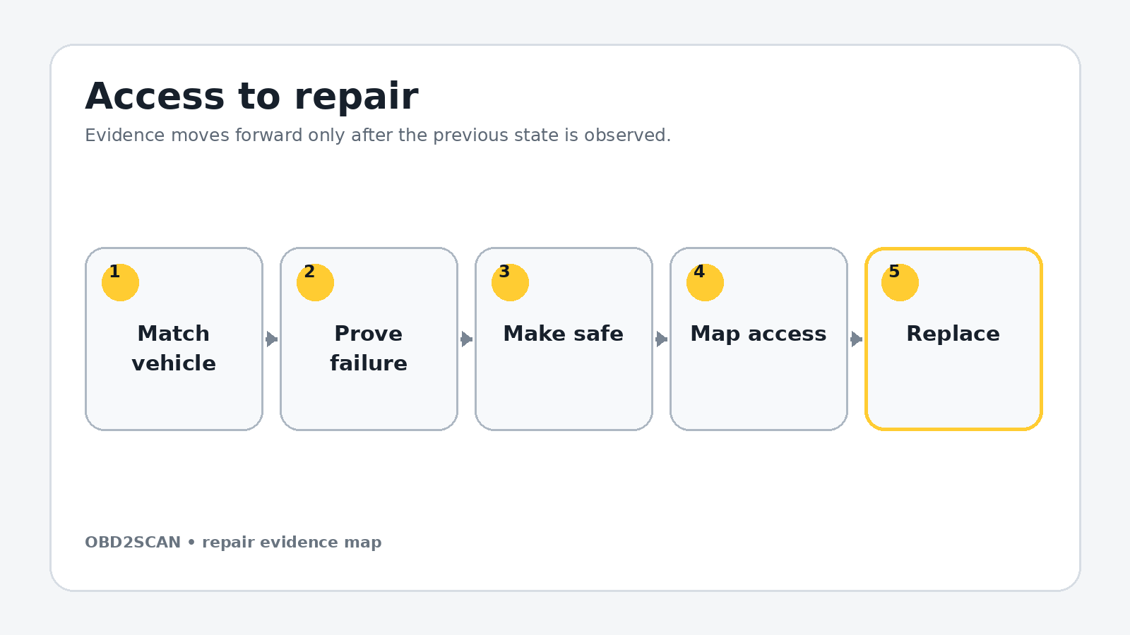
Loosen the right-front wheel fasteners, raise and support the car, remove the wheel, then remove the T25 liner fasteners and the liner. Clean the clutch face so feeler-gauge readings are not altered by debris. Identify the compressor label and clutch design before selecting a puller.
Measure the air gap at three positions and record all values. About 0.3 mm was the documented target, but the compressor-specific specification controls. A tapered or highly uneven gap suggests plate distortion, bearing play or hub damage that a shim change will not correct.
Use separate trays for each access layer, label connectors by destination and photograph every hidden hose before it moves. Mark fastener length and location on a drawn component outline. Reassembly should follow a map created during removal, not memory or wire reach.
Exact repair sequence
Complete the following sequence in order. A bold lead identifies the action; the remaining sentence states the checkpoint that must be true before the next action begins.
- Confirm the coil circuit hot. With the symptom present and all rotating parts protected, verify command, voltage and ground. Shut the engine off and isolate it before mechanical work begins.
- Mark plate-to-hub orientation. Add a witness mark and photograph the existing gap. This makes runout or assembly change visible after repair.
- Install the holding tool. Thread the specified M5 screws only to safe depth in the clutch plate. Do not bottom them into the pulley or coil.
- Remove the center fastener. Hold the plate with the tool and use the correct socket. Capture the washer and note its orientation.
- Install the puller. Use the compressor-approved center tool or documented M6 reaction setup. Tighten the three puller screws evenly so the plate comes straight off the splined hub.
- Capture the shim stack. Remove the plate over a clean tray. Measure and label every tiny shim rather than assuming how many are present.
- Calculate, do not guess. Required shim reduction equals measured excess gap, while preserving the compressor-specified minimum. Select a combination that keeps the final gap inside range at all three points.
- Inspect wear limits. Replace the clutch assembly if the friction face is blue, cracked, deeply grooved, loose or too worn to reach specification with a safe shim stack. Check pulley bearing play and coil resistance.
- Install the selected shims. Place them flat on the hub, align the witness marks and use the approved clutch installer or center-fastener draw-in method. Do not hammer on the compressor shaft or plate.
- Torque the center fastener. Use the compressor-specific value and replacement rule. Rotate the pulley by hand and confirm the plate does not drag when disengaged.
- Measure at three points again. Record the smallest and largest gaps. If the minimum is below specification or variation is excessive, remove the plate and correct the stack or replace distorted parts.
- Remove every service tool. Count the three M5 screws, puller and center tool before any engine-running test.
Reassembly and torque control
Before the liner returns, reconnect any coil wiring disturbed for testing and secure it away from the pulley. Spin the pulley by hand. Confirm the clutch plate has clearance around its full circumference and no tool, loose shim or fastener remains.
Use the voltage and ground test method to document coil supply under command. A successful mechanical adjustment with excessive circuit voltage drop will still fail when the coil becomes hot.
| Fastener or setting | Documented value | Applicability gate |
|---|---|---|
| Clutch center fastener | Use compressor-specific service data | Do not infer from bolt diameter |
| Clutch air gap | About 0.3 mm documented | Compressor ID and current specification control |
| Wheel fasteners | Use Volvo model/wheel specification | Final torque on the ground |
Torque boundary: Values in this table belong to the documented configuration. Check current VIN/engine-specific service data, bolt material, replacement rule and torque sequence before applying them.
Fluids, adaptations, and first start
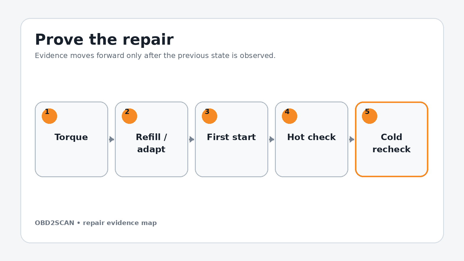
With all people and tools clear, start the engine from outside the wheel-well hazard zone. Command A/C on and off while observing the plate. It must engage promptly without slip and fully release without continuous rubbing. Stop immediately for sparks, scraping, smoke or pulley wobble.
Run the system until it exceeds the original cut-out time. Record vent temperature, ambient temperature, clutch command, pressure data and cycling behavior. The goal is not continuous engagement; it is reliable response whenever the control module commands engagement.
Prove the repair under the original condition
After the compressor heat-soaks, repeat on/off commands several times. Recheck the gap after shutdown. A gap that changes or a plate that drags indicates incorrect seating, bearing play or fastener movement. Refit the liner and wheel only after the hot test passes, then torque the wheel correctly.
Road-test in the original ambient and traffic condition. The repair is complete when clutch command and physical response agree hot and cold, vent performance remains stable and the disengaged plate does not drag. If cooling remains poor with reliable engagement, resume refrigerant, airflow or compressor-capacity diagnosis instead of reducing the gap further.
Completion standard: Uniform specified gap, clean engage/disengage hot and cold, stable vent performance.
Common ways this repair goes wrong
- Assuming intermittent cooling always means low refrigerant
- Removing shims before proving command, voltage and ground
- Using one feeler-gauge point instead of three
- Removing so much shim that the clutch cannot disengage
- Hammering the plate onto the compressor shaft
- Running the engine with puller hardware or hands near the pulley
A repair is not improved by clearing a code, adding sealant, tightening beyond specification or skipping a blocked step. When a checkpoint fails, return to the last verified state and correct the cause before more parts are installed.
Exact repair checklist
- VIN, engine/chassis code and installed component revision match the planned procedure.
- The failed component or interface was proven before disassembly; the before-state is saved.
- All seals, fluids, required new hardware and special tools are present before access is opened.
- Connectors, hoses, fastener lengths, routing and timing/alignment references are photographed and labeled.
- Open fuel, oil, coolant, intake or refrigerant interfaces are protected and every plug is counted.
- Replacement parts seat without force; every structural or sealing fastener starts by hand.
- Final torque, angle, sequence and ride-height/temperature conditions match current service data.
- All fluids, bleed routines, adaptations or calibrations required by the exact vehicle are complete.
- First start passes the listed stop rules; the repaired area is checked before trim or shields hide it.
- The original symptom is repeated hot and cold, the final scan is saved and the next-morning recheck passes.
Minimum record to retain
Retain the VIN, engine or chassis code, before-scan, symptom conditions, disassembly photos, connector labels, fastener map, service-data revision and every measured value. Record the exact fluid specification and quantity added, all adaptations or bleed routines completed, the first-start observations and a cold recheck. A later technician should be able to tell what was directly observed, what was replaced and which same-condition test proved the repair without relying on the invoice description.
- The clutch is accessed through the right-front wheel well without opening the refrigerant circuit.
- About 0.3 mm was the documented target air gap.
- The gap repair applies only when command and coil power remain but hot engagement fails.
- The engine must never run with puller tools attached or the clutch plate removed.
This workflow is marked completed only when its stated repair and post-repair checks are represented. It does not certify an unseen vehicle, replace current service information or convert a different engine/chassis variant into the documented configuration.






Comments 0
Questions, fixes, and real-world diagnostic notes from readers.
Be the first to share a diagnostic result or ask a follow-up question.