
Volvo P1 Water Pump and Timing Belt: Lock, Replace, Rotate, Recheck

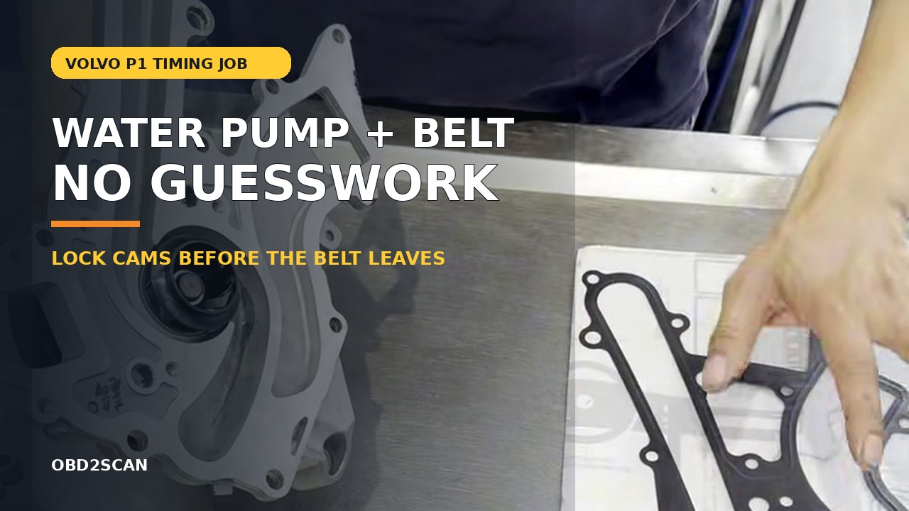
Bottom line: A Volvo P1 water-pump and timing-belt repair covering cam locks, engine support, pump installation, belt tension, two hand rotations and first-start verification.
Can you know how to repair it from this page? Yes—after the vehicle and failure match. The article identifies the staged parts and tools, access layers, removal and installation sequence, torque gates, fluid or adaptation work, first-start stop rules and the same-condition test that closes the job.
In this case
- Repair at a glance
- Confirm the repair before disassembly
- Parts, tools, and consumables to stage
- Preparation and safety boundary
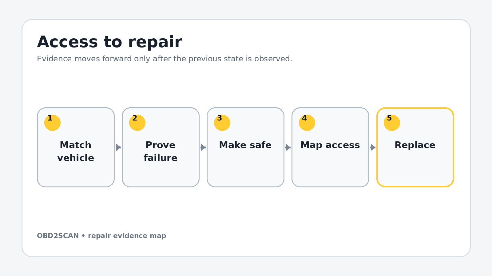
- Remove the access layers without losing the map
- Exact repair sequence
- Reassembly and torque control
- Fluids, adaptations, and first start
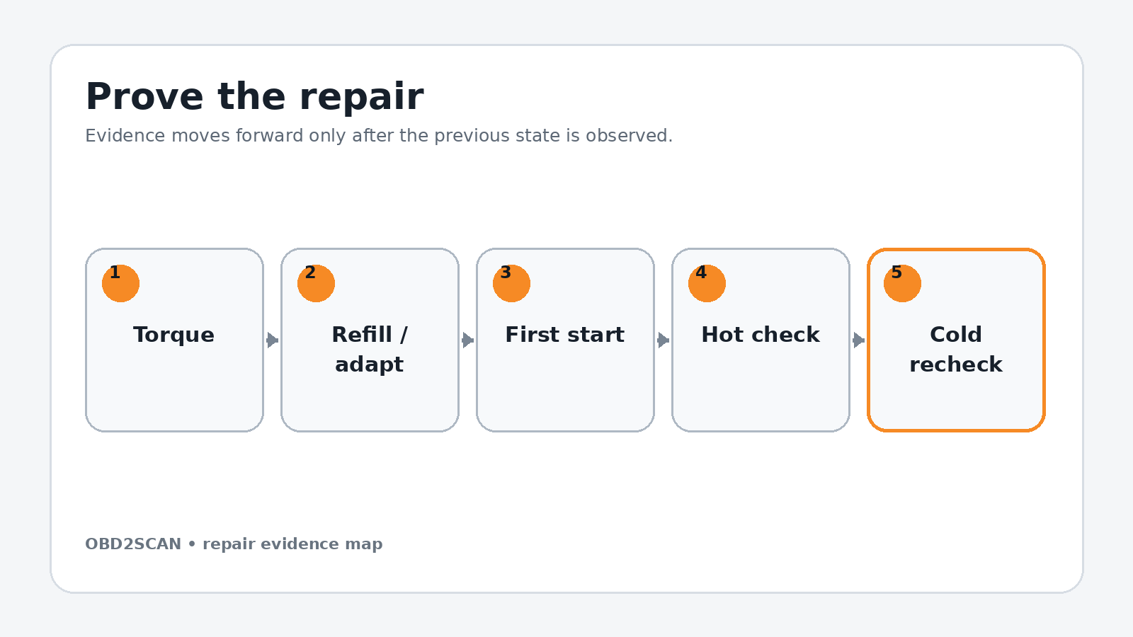
- Prove the repair under the original condition
- Common ways this repair goes wrong
- Exact repair checklist
- Minimum record to retain
Repair at a glance
| Field | Repair detail |
|---|---|
| Applies to | 2005–2013 P1 five-cylinder configurations only after engine-code confirmation |
| Repair trigger | Verified pump leakage/play or scheduled belt service with pump access justified |
| Parts | Pump, gasket, timing belt, tensioner, idler and disturbed cam seals/covers |
| Time / difficulty | Full day; advanced and interference-engine critical |
| Stop point | Correct cam-locking/counterhold tools or current timing data are unavailable |
| Proof complete | Two hand rotations, marks and tension rechecked, dry cooling system, clean first start |
Confirm the repair before disassembly
Confirm the leak before opening the timing drive. Pressure-test the cold cooling system and inspect the pump drain path from the wheel well. Coolant from the expansion tank, thermostat or hose can travel along the timing cover. Check pump bearing play only with the belt unloaded and according to service data.
Read the engine code and current timing procedure. The P1 model range includes variations in cam control, seals and accessory layout. If the correct lock, counterhold or torque/angle information is missing, use the DIY-versus-shop decision guide and stop before the belt is loosened. This is an interference-engine job; approximate marks are not an acceptable substitute.
Do not continue when: Correct cam-locking/counterhold tools or current timing data are unavailable.
Parts, tools, and consumables to stage
Stage the complete job before access is opened. Part numbers, seals, bolt-reuse rules and fluid specifications must be matched to the VIN, engine or chassis code; a familiar model name is not precise enough.
| Parts and consumables | Tools and support equipment |
|---|---|
| • Engine-code-correct water pump and gasket • Timing belt, tensioner and idler • Camshaft seals and rear covers if opened by the selected procedure • Accessory/A/C belt if worn or contaminated • Specified coolant • Engine-mount and crank/cam hardware identified as single-use • Oil-pump reseal parts only if an active leak is verified | • Volvo-compatible rear camshaft locking kit • Approved crankshaft counterhold and 30 mm service tools • Camshaft-seal installation tool • T25, T30, T50 and T55 sockets plus metric sockets/wrenches • Low- and high-range torque wrenches with angle capability where specified • Engine support, jack stands and wheel chocks • Drain pan, belt-tension tool and inspection mirror |
Preparation and safety boundary
Work cold, disconnect the battery and support the right side of the engine before removing its mount. The jack or support must contact an approved load point with a suitable pad; the oil pan is not automatically a safe lifting point. Support the car independently before removing the right-front wheel and liner.
Never loosen the crank or cam fasteners by asking the timing belt or locking tool to absorb uncontrolled torque unless the current procedure explicitly permits it. Use the proper counterhold. Mark direction on any reused belt during inspection, keep oil and coolant off the new belt, and stop if a cam jumps against valve-spring pressure.
Remove the access layers without losing the map
Remove the intake tube, its vacuum lines, MAF housing, ignition-coil cover, upper timing covers and cam-sprocket guard. Move the expansion tank without stressing its hoses. Inspect behind both cam sprockets for oil before deciding whether seal work belongs in the scope.
Raise and support the car, remove the right-front wheel, fender liner, lower shields and accessory belt. Use the approved counterhold to remove the crank pulley hardware. Drain coolant cold, support the engine, remove the upper mount and expose the center timing cover.
Use separate trays for each access layer, label connectors by destination and photograph every hidden hose before it moves. Mark fastener length and location on a drawn component outline. Reassembly should follow a map created during removal, not memory or wire reach.
Exact repair sequence
Complete the following sequence in order. A bold lead identifies the action; the remaining sentence states the checkpoint that must be true before the next action begins.
- Clear the rear cam area. Disconnect coil and cam-sensor wiring, label the two sensor wheels and remove only the covers and wheels required by the exact locking procedure.
- Set the engine at the specified timing position. Rotate only in the normal direction with a hand tool. Align the crank/oil-pump references and confirm the rear cam slots are in the required orientation.
- Install the rear cam locks. Seat both halves fully and secure the bridge. If the tool needs force or the slots are not level as specified, rotate and diagnose the mismatch; do not clamp the cams into position.
- Add independent witness marks. Mark cam sprockets, fixed references and belt direction as a secondary check. Marks document position but do not replace the locking tools.
- Release belt tension. Loosen the tensioner fastener in a controlled way, remove the timing belt and keep the crank and cams undisturbed. Remove sprockets only when the selected procedure requires seal access.
- Remove the center cover and idler. Store each fastener in a drawn location. Remove the engine-mount bracket in the specified sequence while the engine remains securely supported.
- Remove the seven pump bolts. Work through the wheel-well access, support the pump and catch residual coolant as the seal releases. Note the two alignment-pin holes in the gasket.
- Prepare the pump face. Protect openings, remove gasket residue without scratching and inspect the alignment pins. Use only the small approved amount of sealant at the exact retention points if the service procedure calls for it.
- Install the pump squarely. Place the gasket on its alignment pins, seat the pump without folding the gasket and start all seven bolts by hand. Tighten in progressive passes to the engine-code-specific specification.
- Install new idler and tensioner. Ensure the tensioner rear tab engages the block feature. Leave it adjustable until the new belt is routed in the correct direction around every sprocket.
- Set belt tension at the specified temperature. Rotate the tensioner with the 6 mm tool until its indicator sits at the required position, then tighten the fastener without letting the pointer move.
- Remove locks and rotate by hand. With spark plugs removed if the procedure allows easier feel, rotate the crank two complete revolutions in the normal direction. Stop immediately at hard resistance; never use the starter to find out whether timing is correct.
- Return to the timing position. Refit the locks without force, compare every witness mark and recheck the tension indicator. If any check is wrong, release tension and time the engine again before covers return.
If the exact Volvo procedure publishes a belt-frequency specification, the FXTUL sonic belt tension tester can add a repeatable tension measurement before the engine is rotated by hand; it does not replace the locking tools or timing-mark checks.
Reassembly and torque control
Install new cam seals with the correct driver only if they were removed; a cocked seal can create an immediate belt-contaminating leak. Refit each labeled sensor wheel to its original cam. Restore the center and outer timing covers, engine-mount bracket, upper mount, crank pulley and accessory drive using current bolt-reuse and torque/angle instructions.
Reconnect the expansion tank, every ground and cam/coil connector, MAF housing, vacuum lines and intake. Hand-turning the engine remains the last action before the covers hide the belt. Photograph the final marks and tensioner pointer. Do not install the wheel-liner package until the first leak inspection is possible.
| Fastener or setting | Documented value | Applicability gate |
|---|---|---|
| Camshaft sprocket bolts | 120 Nm | Documented five-cylinder configuration; use counterhold and verify hardware rule |
| Camshaft sprocket plugs | 35 Nm | Documented configuration |
| Cam-position sensor wheels | 20 Nm | Return each wheel to its original cam |
| Oil-pump bolts if resealed | 10 Nm | Only when an active oil-pump leak justifies the added work |
| Pump, tensioner, idler, crank and mount hardware | Use current engine-code data | Do not infer from head size |
Torque boundary: Values in this table belong to the documented configuration. Check current VIN/engine-specific service data, bolt material, replacement rule and torque sequence before applying them.
Fluids, adaptations, and first start
Close the drain and refill with the specified coolant using the approved vacuum-fill or bleed method. A cold cooling-system pressure test should hold before the engine runs. Rotate by hand one final time if any timing component was disturbed after the documented check.
Start without touching the accelerator. Shut down immediately for a sharp repeating noise, belt walk, oil-pressure warning or timing/cam correlation fault. Observe the tensioner and pump area from a safe distance, then let the engine warm while monitoring coolant temperature and cabin heat.
Prove the repair under the original condition
Scan for cam correlation, coolant-temperature and misfire faults. Inspect the pump, cam seals and timing covers for coolant or oil. Confirm the belt remains centered and the tension indicator behaves as specified. Do not road-test an engine that overheats, lacks cabin heat or develops a new mechanical noise.
After cooling completely, correct coolant level and pressure-test again. Reinspect after the first road cycle. The repair is complete only when timing checks remain valid, the cooling system is dry and stable, and the engine starts and runs with no new correlation fault.
Completion standard: Two hand rotations, marks and tension rechecked, dry cooling system, clean first start.
Common ways this repair goes wrong
- Using paint marks without the rear cam locks
- Removing the engine mount before independently supporting the engine
- Using an impact where a counterhold and measured torque/angle are required
- Allowing a cam to move after belt removal
- Setting the tension pointer without considering the specified temperature
- Starting the engine before two hand rotations and a full timing recheck
A repair is not improved by clearing a code, adding sealant, tightening beyond specification or skipping a blocked step. When a checkpoint fails, return to the last verified state and correct the cause before more parts are installed.
Exact repair checklist
- VIN, engine/chassis code and installed component revision match the planned procedure.
- The failed component or interface was proven before disassembly; the before-state is saved.
- All seals, fluids, required new hardware and special tools are present before access is opened.
- Connectors, hoses, fastener lengths, routing and timing/alignment references are photographed and labeled.
- Open fuel, oil, coolant, intake or refrigerant interfaces are protected and every plug is counted.
- Replacement parts seat without force; every structural or sealing fastener starts by hand.
- Final torque, angle, sequence and ride-height/temperature conditions match current service data.
- All fluids, bleed routines, adaptations or calibrations required by the exact vehicle are complete.
- First start passes the listed stop rules; the repaired area is checked before trim or shields hide it.
- The original symptom is repeated hot and cold, the final scan is saved and the next-morning recheck passes.
Minimum record to retain
Retain the VIN, engine or chassis code, before-scan, symptom conditions, disassembly photos, connector labels, fastener map, service-data revision and every measured value. Record the exact fluid specification and quantity added, all adaptations or bleed routines completed, the first-start observations and a cold recheck. A later technician should be able to tell what was directly observed, what was replaced and which same-condition test proved the repair without relying on the invoice description.
- Pump access requires the timing belt, idler, engine mount bracket and center cover to move.
- Documented cam-sprocket bolts are 120 Nm, plugs 35 Nm and sensor wheels 20 Nm.
- Camshafts are locked at the rear before the timing belt is removed.
- Timing is hand-rotated and rechecked before the starter is used.
This workflow is marked completed only when its stated repair and post-repair checks are represented. It does not certify an unseen vehicle, replace current service information or convert a different engine/chassis variant into the documented configuration.




Comments 0
Questions, fixes, and real-world diagnostic notes from readers.
Be the first to share a diagnostic result or ask a follow-up question.