
MK7 GTI Intake Manifold Replacement: Fuel, Coolant, Wiring, and Runner Checks

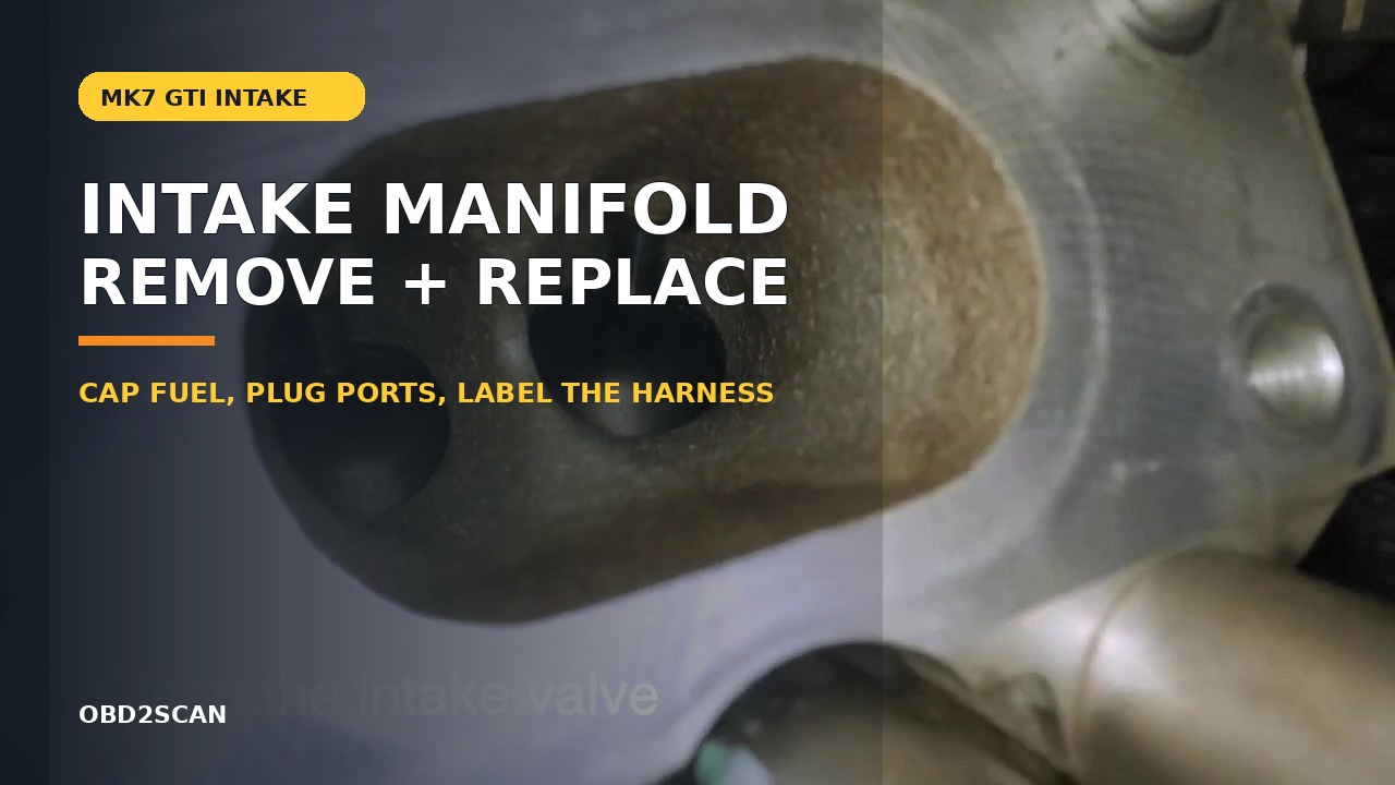
Bottom line: A full MQB 1.8T/2.0T intake-manifold workflow that controls pressurized fuel, hidden lower connections, open ports, runner transfer, reassembly torque and post-repair basic settings.
Can you know how to repair it from this page? Yes—after the vehicle and failure match. The article identifies the staged parts and tools, access layers, removal and installation sequence, torque gates, fluid or adaptation work, first-start stop rules and the same-condition test that closes the job.
In this case
- Repair at a glance
- Confirm the repair before disassembly
- Parts, tools, and consumables to stage
- Preparation and safety boundary
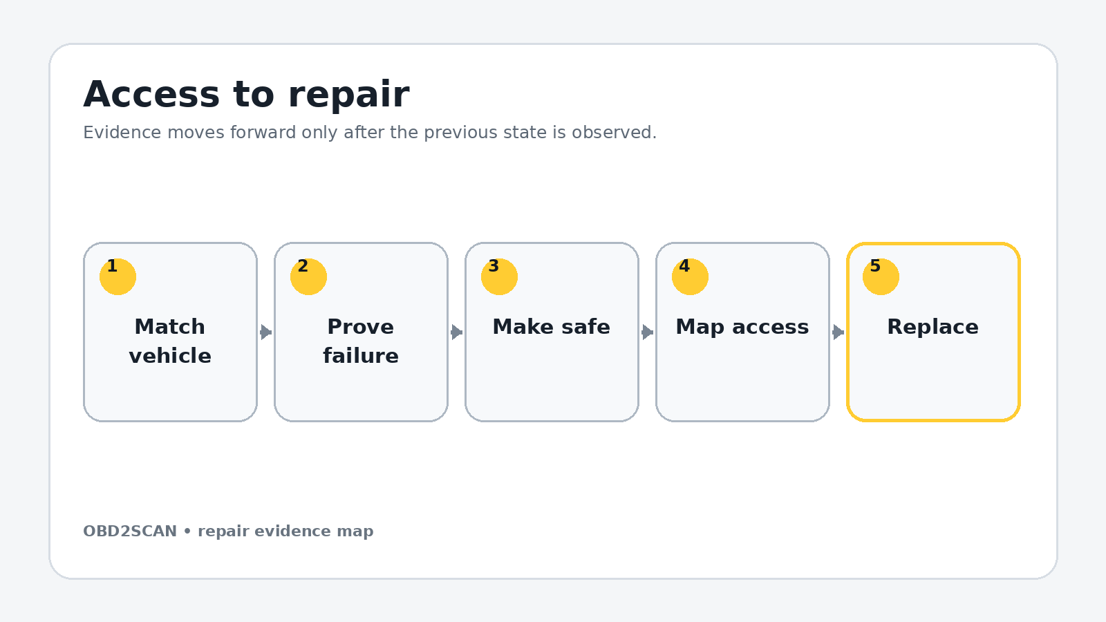
- Remove the access layers without losing the map
- Exact repair sequence
- Reassembly and torque control
- Fluids, adaptations, and first start
- Prove the repair under the original condition
- Common ways this repair goes wrong
- Exact repair checklist
- Minimum record to retain
Repair at a glance
| Field | Repair detail |
|---|---|
| Applies to | 2015–2018 MK7 GTI directly; related MQB 1.8T/2.0T layouts require verification |
| Repair trigger | Confirmed runner mechanism fault, damaged manifold or access for another proven repair |
| Parts | Correct manifold, manifold seals and every disturbed fuel/coolant seal |
| Time / difficulty | Half day; intermediate, with pressurized-fuel precautions |
| Stop point | Fuel cannot be depressurized or an open intake port cannot be positively protected |
| Proof complete | No fuel/coolant/vacuum leak, runner data follows command, no P2014/P2015 return |
Confirm the repair before disassembly
Do not remove the manifold because a code contains the words intake runner. Confirm the runner command, actual position and mechanical response. Inspect the external linkage and connector, then test wiring where data stays fixed. P2014 or P2015 can describe a circuit or range problem; carbon on the valves can cause a different airflow complaint. Record cold idle, fuel trims and runner data before parts move.
If removal is for carbon cleaning, inspect the valves first and define the cleaning method separately. If removal is for high-pressure-pump service, confirm the pump fault before opening fuel connections. The code-to-test diagnostic workflow keeps the reason for disassembly separate from the access operation.
Do not continue when: Fuel cannot be depressurized or an open intake port cannot be positively protected.
Parts, tools, and consumables to stage
Stage the complete job before access is opened. Part numbers, seals, bolt-reuse rules and fluid specifications must be matched to the VIN, engine or chassis code; a familiar model name is not precise enough.
| Parts and consumables | Tools and support equipment |
|---|---|
| • VIN-correct MQB intake manifold • New cylinder-head-to-manifold seals • Throttle-body seal if hardened or damaged • Fuel-line, pump and injector seals or single-use parts required by service data • Coolant-pipe O-rings and specified coolant • Optional runner sensors, nipples or guides only after they fail inspection | • Metric, Torx and M10 triple-square socket sets • 7 mm, 10 mm, 13 mm and 17 mm tools • Low-range torque wrench • Hose-clamp pliers, hose picks and connector picks • Magnetic pickup, inspection mirror and labeled trays • Fuel-safe caps, absorbent pads and eye protection • Scan tool with runner position and basic-setting access |
Preparation and safety boundary
Work cold, disconnect the battery after saving required data and relieve both low- and high-pressure fuel according to current service information. Wear eye protection. A 17 mm union loosened without proper depressurization can spray fuel. Surround the connection with an absorbent pad, loosen it slowly only after pressure is removed, and cap both sides immediately.
Raise the car only at approved points and support it on stands. Coolant is released below the throttle body, so position a drain pan before a hose moves. Plastic coolant necks and grey-lock electrical connectors break when pried in the wrong direction; unlock, support and separate them rather than pulling the harness.
Remove the access layers without losing the map
Remove the engine cover and air-intake assembly, then the front intake duct held by T20 and T25 fasteners. Release the high-pressure line and low-pressure hose at the pump after the system is safe. Remove the belly pan to reach the lower throttle and coolant connections.
Remove the top coolant pipe held by two T30 fasteners and its clamp. Below the throttle body, release the charge hose, coolant hose assembly, MAP connector and two T30 pipe fasteners. Photograph every lower connection before moving upward; most reassembly errors occur in this hidden layer.
Use separate trays for each access layer, label connectors by destination and photograph every hidden hose before it moves. Mark fastener length and location on a drawn component outline. Reassembly should follow a map created during removal, not memory or wire reach.
Exact repair sequence
Complete the following sequence in order. A bold lead identifies the action; the remaining sentence states the checkpoint that must be true before the next action begins.
- Remove the manifold support. Take out the two upper 13 mm fasteners and lower M10 triple-square fastener, then unclip the harness from the bracket.
- Support and remove the throttle body. Release the four aluminum T30 fasteners with the bit fully seated. Hold the body before the final bolt leaves so it cannot fall or strain its connector.
- Free the harness in zones. Work from one end of the manifold to the other. Slide grey secondary locks before pressing connector tabs; label connectors that can reach more than one sensor.
- Remove the small manifold bracket. Two T30 fasteners secure it beneath the harness. Release its remaining connector after the bracket can be moved into view.
- Remove the filter cap only for required clearance. Use the correct 32 mm cap tool, protect the opening and retain its O-ring position. Torque the cap only to the current marked or service-data value during reassembly.
- Disconnect the final sensors. Check both ends and the underside of the manifold for grey locks, vacuum hoses and clipped harness sections before touching manifold bolts.
- Remove the ten manifold fasteners. The documented layout has two 10 mm-head screws and eight T30 screws. Use a magnetic tool so a dropped fastener does not disappear into the engine bay.
- Release the HPFP attachment. Remove the obstructing bracket T30, then the pump-to-manifold T30. Keep all fuel interfaces capped and do not bend the rigid high-pressure line to create room.
- Pull the manifold away from the head. Disconnect the rail end only if the exact layout demands it. Lift the assembly enough to expose and release the underside vacuum-line group rather than tearing it blind.
- Protect the ports immediately. Install counted clean plugs before scraping the head face. Never scrape toward an open port and never allow cleaner to pool inside a cylinder.
- Transfer only inspected components. Move runner guides, sensors, nipples and brackets to the replacement in the same orientation. Replace brittle seals and confirm that the runner moves freely without binding.
- Install new manifold seals. Seat them fully, remove every port plug by count, position the manifold squarely and hand-start all fasteners before any one fastener is tightened.
Reassembly and torque control
Tighten the manifold in an even pattern to 9 Nm on the documented configuration. Install the bracket at 10 Nm for its upper fasteners and 20 Nm for the lower M10 fastener. Fit the throttle body with its seal correctly located and tighten its four fasteners to 7 Nm. Confirm these values against the exact manifold revision and bolt material.
Reconnect the HPFP bracket, capped fuel lines, every manifold sensor, lower MAP connection, coolant and charge hoses, top coolant pipe, intake duct and air intake. Pull gently on each grey-lock connector and hose coupling. Use the rough-idle evidence map if trims or misfires change after the work; a reassembly leak is more likely than a new unrelated fault.
| Fastener or setting | Documented value | Applicability gate |
|---|---|---|
| Manifold T30 and 10 mm-head fasteners | 9 Nm | Documented MK7 configuration |
| Upper manifold bracket | 10 Nm | 13 mm-head fasteners |
| Lower manifold bracket | 20 Nm | M10 triple-square fastener |
| Throttle body | 7 Nm | Aluminum T30 fasteners; seat tool fully |
| Oil-filter cap | Use current cap marking/service data | A conflicting secondary decimal value was intentionally excluded |
Torque boundary: Values in this table belong to the documented configuration. Check current VIN/engine-specific service data, bolt material, replacement rule and torque sequence before applying them.
Fluids, adaptations, and first start
Refill the cooling system with the approved coolant and perform the model-specific bleed. Prime the fuel system without cranking as directed, then inspect every opened joint with good lighting. Do not start if fuel odor or wetness is present.
Start and hold at idle while watching rail pressure, fuel trims, coolant temperature, runner command and runner position. Run the intake-runner or throttle basic setting only when current service information calls for it. Stop for an oil-pressure warning, fuel leak, uncontrolled idle or rapidly falling coolant level.
Prove the repair under the original condition
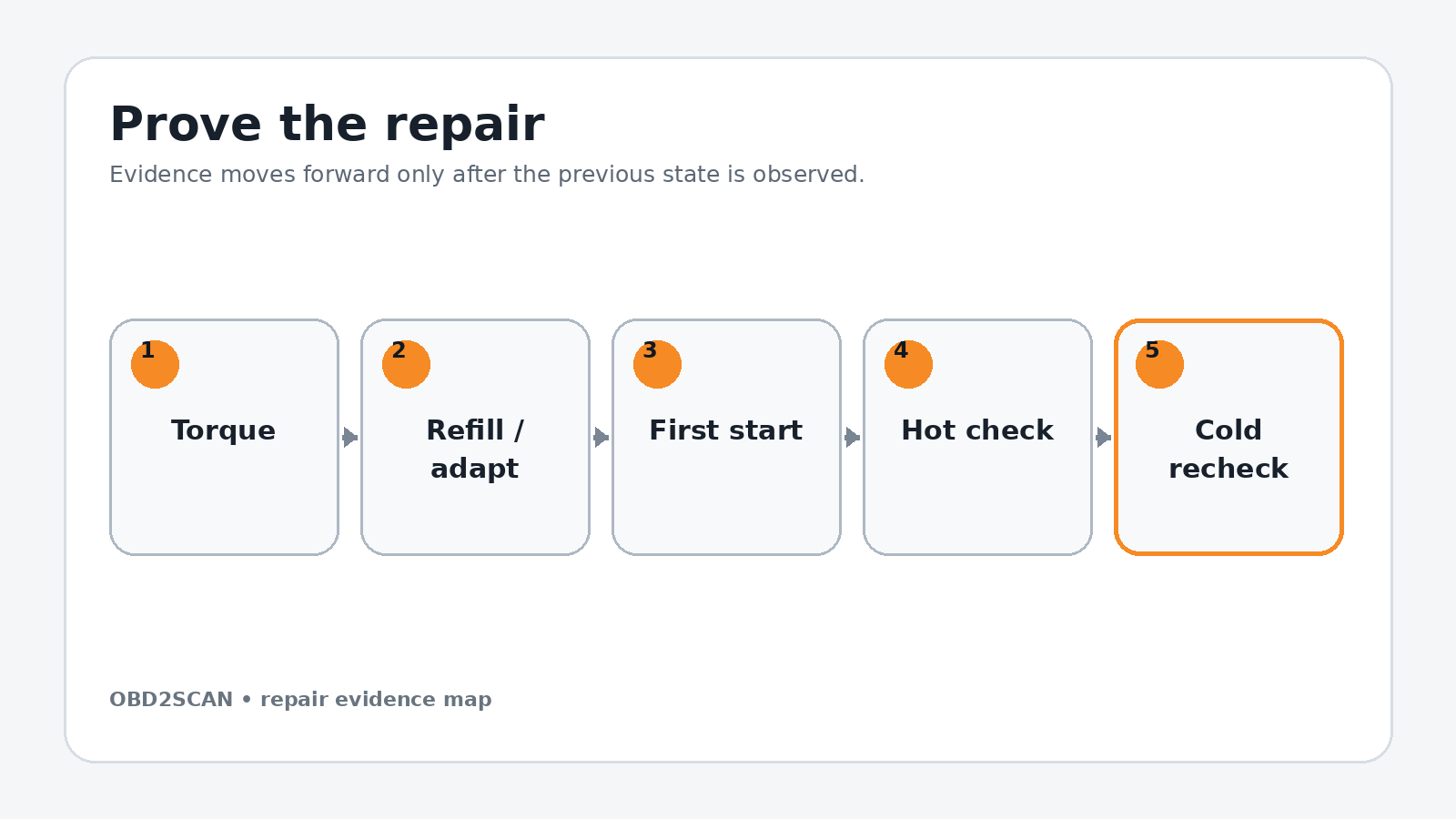
With the engine hot, inspect the manifold perimeter for a hiss, smoke-test only with an approved low-pressure method if needed, and check every coolant connection below the throttle body. Command the runner through its range and confirm actual position follows without sticking. Clear codes only after saving the before and after records.
After a full cold soak, recheck coolant level and all fuel connections. Road-test through the load and rpm region that originally set the fault, then scan again. The repair is complete only when runner data, trims and drivability are normal and no fuel, coolant or vacuum leak was introduced. After the manifold, throttle body, fuel seals, and vacuum connections are restored, the FXTUL automotive smoke leak detector can make a small intake leak easier to locate before adaptations or the new runner assembly are blamed.
Completion standard: No fuel/coolant/vacuum leak, runner data follows command, no P2014/P2015 return.
Common ways this repair goes wrong
- Replacing the manifold without proving whether the fault is electrical, mechanical or carbon-related
- Loosening high-pressure fuel while pressure remains
- Breaking a hidden coolant neck or grey-lock connector
- Dropping a manifold fastener or debris into an open port
- Trusting reverse-order reassembly without a lower-connection photo map
- Skipping runner basic settings or same-condition fault verification when the exact repair requires them
A repair is not improved by clearing a code, adding sealant, tightening beyond specification or skipping a blocked step. When a checkpoint fails, return to the last verified state and correct the cause before more parts are installed.
Exact repair checklist
- VIN, engine/chassis code and installed component revision match the planned procedure.
- The failed component or interface was proven before disassembly; the before-state is saved.
- All seals, fluids, required new hardware and special tools are present before access is opened.
- Connectors, hoses, fastener lengths, routing and timing/alignment references are photographed and labeled.
- Open fuel, oil, coolant, intake or refrigerant interfaces are protected and every plug is counted.
- Replacement parts seat without force; every structural or sealing fastener starts by hand.
- Final torque, angle, sequence and ride-height/temperature conditions match current service data.
- All fluids, bleed routines, adaptations or calibrations required by the exact vehicle are complete.
- First start passes the listed stop rules; the repaired area is checked before trim or shields hide it.
- The original symptom is repeated hot and cold, the final scan is saved and the next-morning recheck passes.
Minimum record to retain
Retain the VIN, engine or chassis code, before-scan, symptom conditions, disassembly photos, connector labels, fastener map, service-data revision and every measured value. Record the exact fluid specification and quantity added, all adaptations or bleed routines completed, the first-start observations and a cold recheck. A later technician should be able to tell what was directly observed, what was replaced and which same-condition test proved the repair without relying on the invoice description.
- The manifold is blocked by lower coolant, throttle and bracket connections as well as the HPFP attachment.
- Documented manifold fasteners are 9 Nm and throttle-body fasteners 7 Nm.
- The high-pressure fuel circuit must be made safe and capped.
- Runner command versus position and leak checks close the repair.
This workflow is marked completed only when its stated repair and post-repair checks are represented. It does not certify an unseen vehicle, replace current service information or convert a different engine/chassis variant into the documented configuration.






Comments 0
Questions, fixes, and real-world diagnostic notes from readers.
Be the first to share a diagnostic result or ask a follow-up question.