
BMW N55 Valve Cover and PCV Replacement: A 24-Bolt Reassembly Map

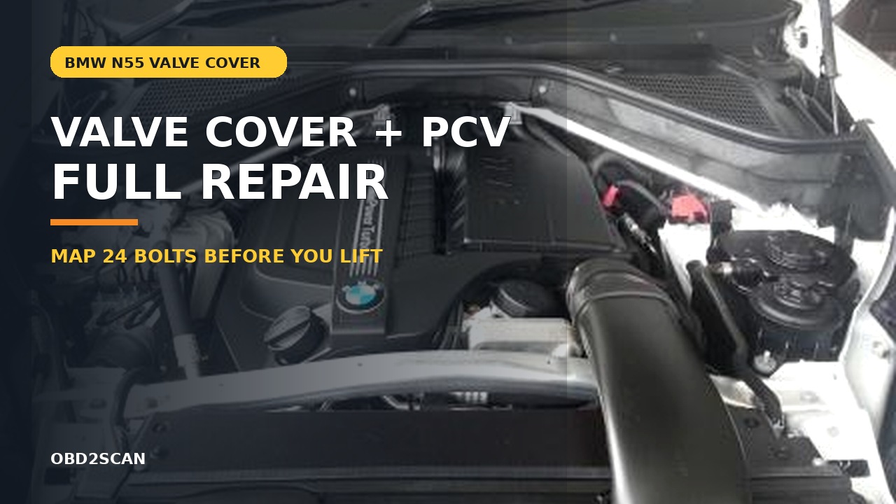
Bottom line: A complete N55 valve-cover and integrated-PCV repair covering fuel-system access, connector control, gasket placement, cross-pattern torque, first start and crankcase-vacuum verification.
Can you know how to repair it from this page? Yes—after the vehicle and failure match. The article identifies the staged parts and tools, access layers, removal and installation sequence, torque gates, fluid or adaptation work, first-start stop rules and the same-condition test that closes the job.
In this case
- Repair at a glance
- Confirm the repair before disassembly
- Parts, tools, and consumables to stage
- Preparation and safety boundary
- Remove the access layers without losing the map
- Exact repair sequence
- Reassembly and torque control
- Fluids, adaptations, and first start
- Prove the repair under the original condition
- Common ways this repair goes wrong
- Exact repair checklist
- Minimum record to retain
Repair at a glance
| Field | Repair detail |
|---|---|
| Applies to | BMW N55 vehicles after confirming cover and fuel-line arrangement by VIN |
| Repair trigger | Verified cover seam leak, cracked cover or failed integrated PCV |
| Parts | Complete cover or gasket set, seals disturbed during access, fuel-line hardware as required |
| Time / difficulty | About six hours for a prepared intermediate technician |
| Stop point | Fuel pressure cannot be safely relieved or the Valvetronic area cannot be identified |
| Proof complete | Dry cover, stable crankcase vacuum, no fuel odor, misfire or mixture fault |
Confirm the repair before disassembly
Trace oil to the highest fresh point. Oil from the oil-filter housing, filler cap, vacuum pump area or a spill can collect along the cover seam. A smoke complaint also needs the exhaust-side seam inspected from the rear. Clean, run and recheck before ordering the largest part in the area.
Separate gasket failure from integrated PCV failure. A whistle, abnormal crankcase vacuum, mixture faults or a cap that is extremely difficult to lift at idle can support a PCV problem, but the cap test is not a calibrated measurement. Inspect the diaphragm path and measure crankcase pressure using the approved adapter. Use the rough-idle evidence map if misfire or mixture symptoms remain after obvious external leaks are excluded.
Do not continue when: Fuel pressure cannot be safely relieved or the Valvetronic area cannot be identified.
Parts, tools, and consumables to stage
Stage the complete job before access is opened. Part numbers, seals, bolt-reuse rules and fluid specifications must be matched to the VIN, engine or chassis code; a familiar model name is not precise enough.
| Parts and consumables | Tools and support equipment |
|---|---|
| • Complete N55 valve cover when the integrated PCV or plastic shell is suspect • Valve-cover gasket set if the reusable cover passes inspection • Ignition-coil and sensor seals included for the exact cover • Fuel-line or injector seals and one-time-use hardware required by current service data • Intake seals if the exact installation requires manifold movement • Absorbent pads, port caps and approved cleaning agent | • E12 and metric socket sets with short and wobble extensions • Low-range torque wrench capable of 8.5 Nm • Fuel-line wrenches and approved depressurization equipment • Connector picks, hose tools and ignition-coil puller • Inspection mirror, bright work light and labeled fastener board • Scan tool capable of N55 Valvetronic and mixture data |
Preparation and safety boundary
Begin with a cold engine, record the full scan and disconnect the battery negative after completing any required pressure-relief setup. High-pressure fuel can penetrate skin. Relieve pressure by the exact service procedure, wear eye protection, surround the connection with absorbent material and cap every opened line immediately.
The Valvetronic connector, oxygen-sensor leads, wastegate connector, ground points and brittle vacuum lines all occupy the work area. Release locks before pulling. Photograph both sides and the rear of the cover, then tag each connector by destination rather than trusting wire length during reassembly.
Remove the access layers without losing the map
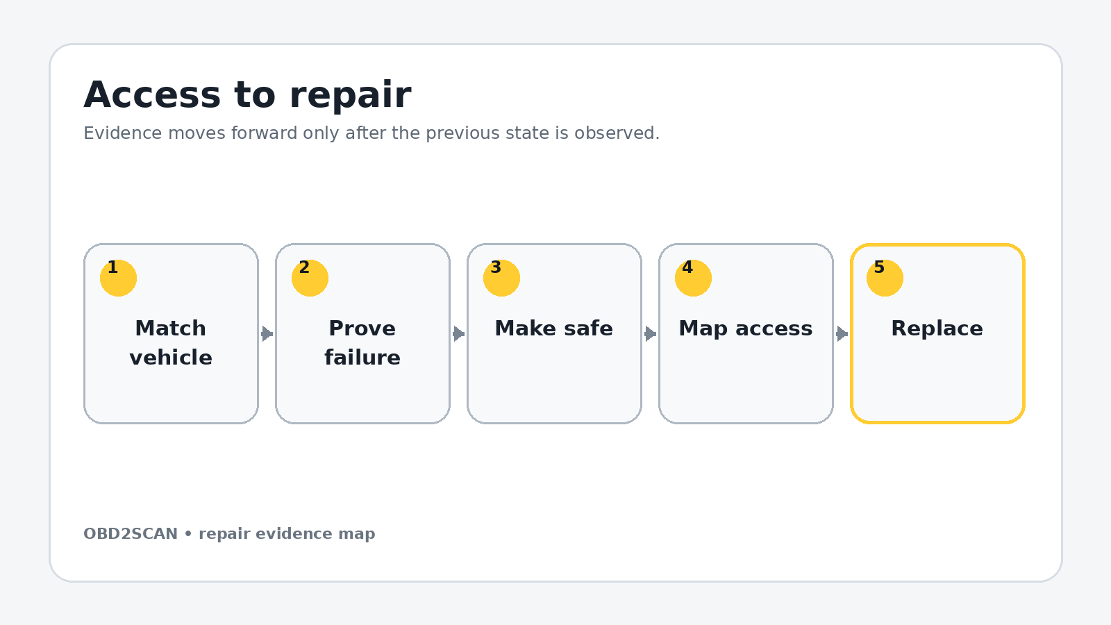
Remove the engine cover, air intake and inlet pipe. Open the cowl area and remove braces only as required by the chassis. Record brace orientation and whether its fasteners are single-use. Move the harness channels without cutting factory retainers where a releasable lock exists.
Disconnect ignition-coil connectors and remove the coils. Release the wastegate, oxygen-sensor and Valvetronic connections, vacuum lines and cable holders from the cover. Depressurize and disconnect the small and large fuel lines in the correct order. Move the fuel rail or associated bracket only as the VIN-specific layout requires, protecting every open fuel interface.
Use separate trays for each access layer, label connectors by destination and photograph every hidden hose before it moves. Mark fastener length and location on a drawn component outline. Reassembly should follow a map created during removal, not memory or wire reach.
Exact repair sequence
Complete the following sequence in order. A bold lead identifies the action; the remaining sentence states the checkpoint that must be true before the next action begins.
- Build a 24-position bolt map. Sketch the cover and push each E12 fastener through its matching position as it is removed. Rear fasteners are easy to miss and difficult to identify by touch.
- Remove grounds and hidden retainers. Check the rear edge with a mirror. A still-attached ground strap, vacuum line or harness clip can crack the cover when it is lifted.
- Loosen the cover progressively. Work from the outer area toward the center in several passes. Confirm all 24 fasteners are free before separating the gasket from the head.
- Lift without contacting Valvetronic hardware. Create rear clearance at the cowl, keep the cover level and stop if it catches. Do not force the plastic shell past the eccentric-shaft or sensor area.
- Protect the open cylinder head. Install counted, lint-free covers. Remove the old perimeter and plug-well seals, then inspect for hardened fragments that stayed on the head.
- Inspect the reusable decision. Check the cover on a flat surface for cracks, heat distortion, damaged bolt sleeves and PCV faults. A gasket-only repair cannot correct a cracked cover or failed integrated diaphragm.
- Clean the head face outward. Use a plastic tool and cleaner on a wipe. Keep debris out of oil returns and avoid scratching the aluminum. Clean oil from plug wells before the new cover is fitted.
- Seat every new seal. Press the gasket fully into the cover groove and verify the plug-well seals are flat. Use sealant only at the exact joints and quantity identified by current BMW data.
- Lower the cover in one controlled movement. Watch the rear edge and every plug-well seal. Before installing bolts, inspect the full perimeter with a mirror for a rolled or displaced gasket.
- Start all 24 fasteners by hand. Draw the cover down in alternating center-to-edge, side-to-side passes. On the documented configuration, final torque is 8.5 Nm; do not use an impact or substitute feel.
- Restore the fuel system cleanly. Fit required new seals or lines, hand-start unions and use a backup wrench where specified. Documented values include 23 Nm for the smaller line, 30 Nm for the larger line and 13 Nm for fuel-rail mounting; verify the exact configuration.
- Reconnect by the label map. Restore grounds, Valvetronic, oxygen-sensor and wastegate connectors, vacuum lines, coil harnesses, cable carriers, intake parts, cowl and braces. Tug-check every lock before the next layer hides it.
Reassembly and torque control
Before the decorative cover returns, perform a slow visual sweep from the rear passenger side around the entire perimeter. Verify coil boots are dry and fully seated, the harness is not trapped beneath a cover boss, and every fuel-line cap has been removed. Reconnect the battery only after the positive fuel connections and grounds have been checked by a second pass.
The oil-leak source tracing workflow is useful for the post-repair baseline: photograph a dry seam now so any later wetness has a known starting point. Do not clean fuel residue with an ignition source, hot engine or connected work lamp that is not rated for the environment.
| Fastener or setting | Documented value | Applicability gate |
|---|---|---|
| 24 valve-cover fasteners | 8.5 Nm | Documented plastic-cover/aluminum-bolt configuration |
| Small fuel line | 23 Nm | Confirm exact line and replacement rule |
| Large fuel line | 30 Nm | Confirm exact line and replacement rule |
| Fuel-rail mounting | 13 Nm | Documented configuration |
| Intake manifold if removed | 15 Nm | Fresh seals; verify variant |
| Brace fasteners | 34 Nm towers / 100 Nm center | Only where this documented brace layout applies |
Torque boundary: Values in this table belong to the documented configuration. Check current VIN/engine-specific service data, bolt material, replacement rule and torque sequence before applying them.
Fluids, adaptations, and first start
Cycle ignition as required to prime the low- and high-pressure fuel sides without starting. Inspect and smell around every disturbed union. If any wetness appears, switch off and correct it before cranking. Start the engine and be prepared for a slightly longer first crank, but stop for persistent fuel-pressure warnings, sharp mechanical noise or an oil-pressure warning.
Allow idle to settle while monitoring misfire counters, mixture correction, Valvetronic faults and crankcase pressure. A brief adaptation event after battery disconnection may occur, but do not erase a persistent fault as normal learning. Run the current Valvetronic initialization only if the repair procedure or stored fault requires it.
Prove the repair under the original condition
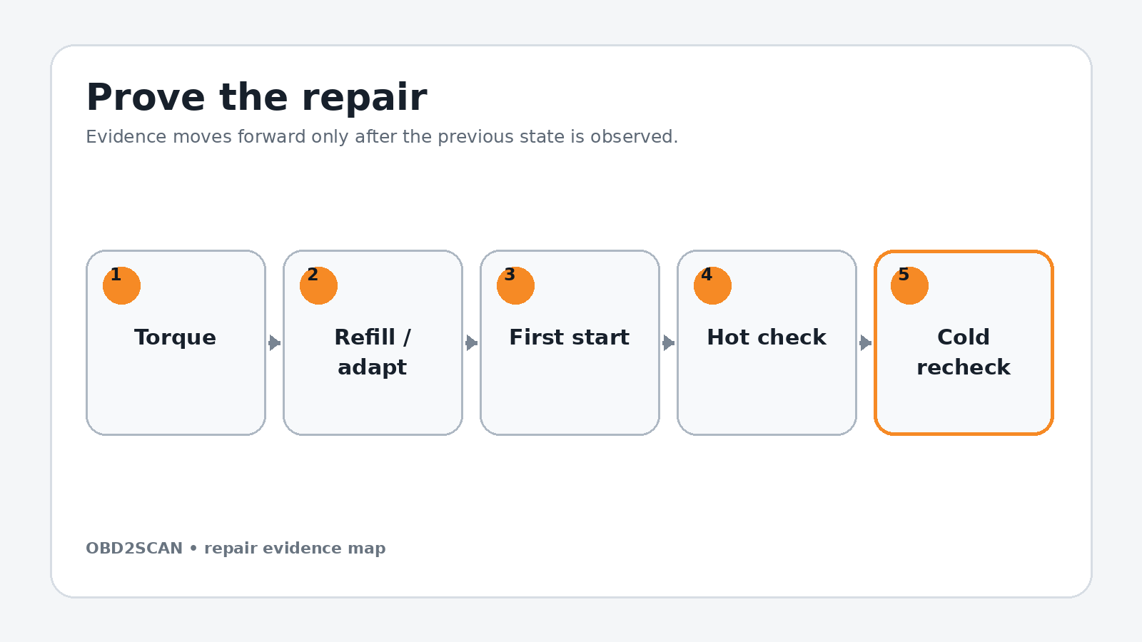
Inspect the entire cover hot with a mirror, especially the rear exhaust side. Confirm no fuel odor, no bubbles or wet unions, no coil-well oil and no pinched vacuum line. Compare measured crankcase pressure with specification; a new cover that is dry but still produces abnormal vacuum has not solved the PCV complaint. During final verification, the AUTOOL SDT206 automotive smoke leak detector can make a remaining PCV or intake leak easier to see before the new valve cover is blamed, using only the permitted low test pressure.
After a full cold soak, repeat the seam, plug-well and fuel checks. Then road-test through idle, light load and boost while saving mixture and misfire data. The repair is complete when the original oil or PCV symptom is absent and no new fuel, intake, Valvetronic or ignition fault was introduced.
Completion standard: Dry cover, stable crankcase vacuum, no fuel odor, misfire or mixture fault.
Common ways this repair goes wrong
- Ordering only a gasket when the plastic cover or integrated PCV has failed
- Pulling fuel lines before pressure is safely relieved
- Missing a rear bolt or ground strap and cracking the cover during removal
- Rolling the new gasket at the firewall side
- Overtightening the 8.5 Nm fasteners
- Treating a cleared mixture fault as proof without measuring crankcase pressure
A repair is not improved by clearing a code, adding sealant, tightening beyond specification or skipping a blocked step. When a checkpoint fails, return to the last verified state and correct the cause before more parts are installed.
Exact repair checklist
- VIN, engine/chassis code and installed component revision match the planned procedure.
- The failed component or interface was proven before disassembly; the before-state is saved.
- All seals, fluids, required new hardware and special tools are present before access is opened.
- Connectors, hoses, fastener lengths, routing and timing/alignment references are photographed and labeled.
- Open fuel, oil, coolant, intake or refrigerant interfaces are protected and every plug is counted.
- Replacement parts seat without force; every structural or sealing fastener starts by hand.
- Final torque, angle, sequence and ride-height/temperature conditions match current service data.
- All fluids, bleed routines, adaptations or calibrations required by the exact vehicle are complete.
- First start passes the listed stop rules; the repaired area is checked before trim or shields hide it.
- The original symptom is repeated hot and cold, the final scan is saved and the next-morning recheck passes.
Minimum record to retain
Retain the VIN, engine or chassis code, before-scan, symptom conditions, disassembly photos, connector labels, fastener map, service-data revision and every measured value. Record the exact fluid specification and quantity added, all adaptations or bleed routines completed, the first-start observations and a cold recheck. A later technician should be able to tell what was directly observed, what was replaced and which same-condition test proved the repair without relying on the invoice description.
- The documented cover uses 24 E12 fasteners and crowded rear access.
- The documented valve-cover fastener torque is 8.5 Nm.
- High-pressure fuel connections and Valvetronic wiring are disturbed during access.
- A complete result includes crankcase-vacuum and fuel-leak checks, not only a dry gasket.
This workflow is marked completed only when its stated repair and post-repair checks are represented. It does not certify an unseen vehicle, replace current service information or convert a different engine/chassis variant into the documented configuration.






Comments 0
Questions, fixes, and real-world diagnostic notes from readers.
Be the first to share a diagnostic result or ask a follow-up question.