
Audi B8 Front Control Arms: Replace All Eight Without Preloading the Bushings


Bottom line: A complete Audi B8 front-control-arm replacement with pinch-bolt planning, knuckle support, upper and lower arm sequencing, simulated ride-height torque and mandatory alignment verification.
Can you know how to repair it from this page? Yes—after the vehicle and failure match. The article identifies the staged parts and tools, access layers, removal and installation sequence, torque gates, fluid or adaptation work, first-start stop rules and the same-condition test that closes the job.
In this case
- Repair at a glance
- Confirm the repair before disassembly
- Parts, tools, and consumables to stage
- Preparation and safety boundary
- Remove the access layers without losing the map
- Exact repair sequence
- Reassembly and torque control
- Fluids, adaptations, and first start
- Prove the repair under the original condition
- Common ways this repair goes wrong
- Exact repair checklist
- Minimum record to retain
Repair at a glance
| Field | Repair detail |
|---|---|
| Applies to | B8 A4/A5/S4/S5/Q5 layouts after PR-code and hardware confirmation |
| Repair trigger | Proven bushing separation or ball-joint play, not noise alone |
| Parts | Upper/lower arms, new nuts/bolts and pinch hardware for both sides |
| Time / difficulty | Five hours when corrosion cooperates; often a full day |
| Stop point | Pinch bolt will not move without unsafe heat or knuckle damage |
| Proof complete | Ride-height final torque, alignment printout, centered wheel and quiet road test |
Confirm the repair before disassembly
Raise and support the car, then test each joint individually. Rocking the wheel can also reveal wheel-bearing or tie-rod play. Use a pry tool beside—not through—the boot and look for joint movement, torn boots, rubber separation or hydraulic-bushing leakage. Noise alone does not identify which of eight arms has failed.
Measure and record ride height from wheel center to fender before lifting. Photograph arm orientation, eccentric marks if present and heat-shield routing. The vehicle-pull diagnostic workflow separates tire force, brake drag and alignment from bushing failure so new arms are not used to solve the wrong complaint.
Do not continue when: Pinch bolt will not move without unsafe heat or knuckle damage.
Parts, tools, and consumables to stage
Stage the complete job before access is opened. Part numbers, seals, bolt-reuse rules and fluid specifications must be matched to the VIN, engine or chassis code; a familiar model name is not precise enough.
| Parts and consumables | Tools and support equipment |
|---|---|
| • VIN/PR-code-correct pair of upper front and rearward arms per side • Forward and rearward lower arms with correct ball joints • New upper pinch bolts, nuts and specified one-time-use bushing hardware • New lower ball-joint and bushing hardware • Wheel bolts only if damaged or stretched • Approved assembly compound only where current Audi data permits it | • Lift or floor jack with four rated stands and wheel chocks • 16, 17, 18 and 21 mm tools plus M12 triple-square • Low/high-range torque wrenches and angle gauge • Ball-joint separator, strut spreader and dead-blow hammer • Knuckle support jack and simulated-ride-height measuring setup • Penetrant, wire brushes and controlled corrosion tools • Alignment appointment or calibrated alignment equipment |
Preparation and safety boundary
Pre-soak the upper pinch bolt hours or days ahead. Heat near aluminum, rubber boots, brake hoses and wheel-speed wiring can cause damage or fire. Use a documented knuckle-safe method and a fire watch; if controlled tools cannot move the bolt, remove the knuckle for bench service or stop for a specialist.
Support the steering knuckle before joints are released. Never let its weight hang from the brake hose, wheel-speed harness or outer CV joint. Keep hands out of a loaded separator’s line of travel and wear eye/face protection; a taper can release violently.
Remove the access layers without losing the map
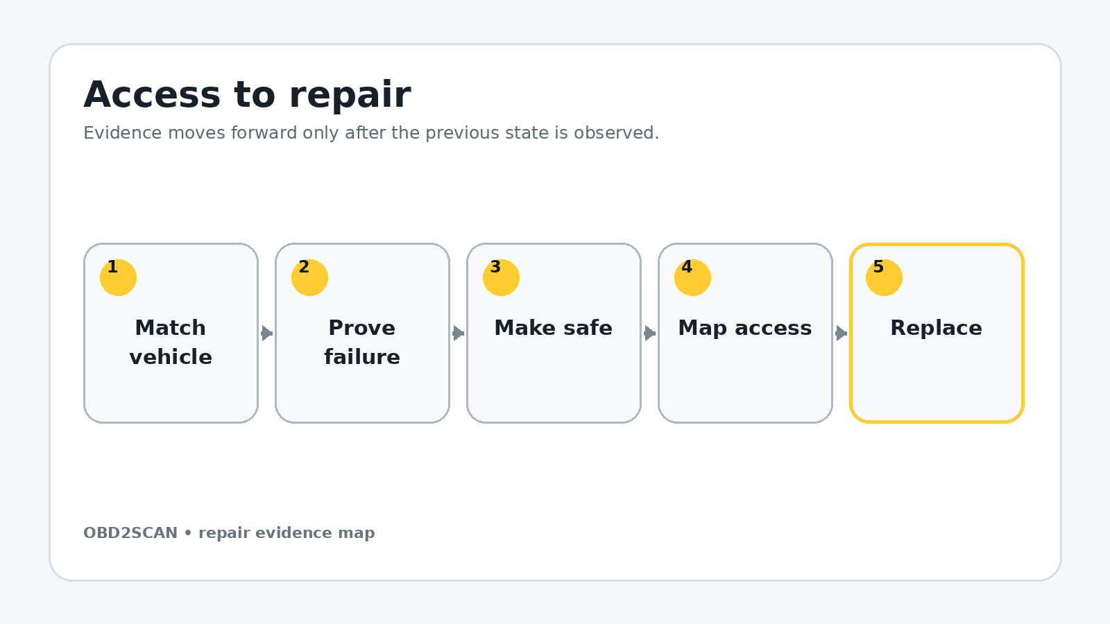
Loosen wheel bolts on the ground, raise the car at approved points, support it and remove both front wheels. Clean exposed threads. Work one side at a time while using the untouched side as an orientation reference, but replace axle pairs consistently when the repair plan calls for a full overhaul.
Support the knuckle. Remove the upper pinch-bolt nut with 16 mm tools, extract the bolt without spreading or cracking the aluminum ears, then separate the two upper joint pins. Clean and inspect the bores before a new bolt is considered.
Use separate trays for each access layer, label connectors by destination and photograph every hidden hose before it moves. Mark fastener length and location on a drawn component outline. Reassembly should follow a map created during removal, not memory or wire reach.
Exact repair sequence
Complete the following sequence in order. A bold lead identifies the action; the remaining sentence states the checkpoint that must be true before the next action begins.
- Replace the upper forward arm. Remove its 16 mm inner bushing bolt, match new-to-old length and orientation, install the new arm and leave the bushing fastener loose.
- Replace the upper rearward arm. Repeat the same process, preserving orientation. Do not final-torque either bonded-rubber bushing while the suspension hangs.
- Seat both upper joint pins. Clean the knuckle bores without enlarging them, insert the joints fully and install new pinch hardware in the specified direction. Use compound only if current Audi instructions permit it.
- Remove the belly pan. Eleven T25 fasteners expose the lower-arm mounts. Store shield hardware separately from structural bolts.
- Release the forward-lower inner mount. Use 18 mm tools and M12 triple-square as required. Support the arm before the last fastener leaves.
- Release the forward-lower ball joint. Remove the 16 mm pinch fastener, use the correct strut spreader and drive the joint out without striking the axle or boot.
- Install its new ball joint. If supplied separately, hold the stud with a 5 mm Allen while tightening the 18 mm nut. The documented bench value is 110 Nm; verify the exact joint revision.
- Install the forward-lower arm loosely. Seat the ball joint and start all new hardware by hand. Leave the inner bonded bushing below final torque.
- Remove the heat shield. The documented shield uses two 10 mm fasteners and one 13 mm fastener. Note which edge overlaps adjacent panels.
- Release the rearward-lower joint. Remove the 21 mm nut and use a ball-joint separator. Support the knuckle and expect a loud release without placing a hand beneath the joint.
- Remove the rearward-lower bushing bolt. Move the heat shield only enough for access, install the new arm and start the replacement hardware without final torque.
- Simulate ride height. With the car securely supported, raise the knuckle at its approved load point until the recorded wheel-center-to-fender dimension is reproduced. Confirm the car remains stable on its stands.
- Final-torque bonded bushings. Apply the VIN-specific torque-plus-angle values only at simulated ride height. Then torque joint and pinch hardware according to its exact bolt size and revision.
Reassembly and torque control
Repeat the sequence on the other side, then reinstall heat shields and belly pan without trapping the wheel-speed wiring. Route brake hoses and sensor leads through every original clip. Spin and steer each hub lock-to-lock while raised to confirm nothing stretches or rubs.
Install wheels, lower the car and torque the wheel bolts to 120 Nm on the documented setup. Drive directly and gently to alignment. If the task, corrosion or support method exceeds the limits in the DIY-versus-shop decision guide, stopping with the suspension safely supported is better than damaging an aluminum knuckle.
| Fastener or setting | Documented value | Applicability gate |
|---|---|---|
| Upper bushing fasteners | 50 Nm + 90° | Documented 16 mm hardware; final torque at ride height |
| Upper pinch bolt | 40 Nm | Documented hardware; confirm bolt diameter/revision |
| Forward-lower ball-joint nut | 110 Nm | Documented 18 mm nut |
| Forward-lower inner nut | 90 Nm + 90° | Verify exact location and hardware |
| Forward-lower inner bolt | 70 Nm + 180° | Ride-height final torque |
| Rearward-lower inner bolt | 70 Nm + 180° | Ride-height final torque |
| Rearward-lower ball-joint nut | 145 Nm | Documented 21 mm nut |
| Wheel bolts | 120 Nm | Clean, dry seats unless service data says otherwise |
Torque boundary: Values in this table belong to the documented configuration. Check current VIN/engine-specific service data, bolt material, replacement rule and torque sequence before applying them.
Fluids, adaptations, and first start
A basic setting is not normally the closing step for mechanical arms, but steering-angle and driver-assistance systems may require calibration after alignment depending on equipment. Scan the chassis modules before and after. Do not clear a wheel-speed or steering fault until wiring and geometry have been checked.
The alignment rack is part of the repair. Provide the technician the ride-height measurement and parts replaced. Request before/after camber, caster and toe data, steering-wheel centering and a note if any value cannot be brought into range. After all control arms are installed and their bonded bushings are tightened at ride height, the AUTOOL XC508 3D wheel alignment system can document final toe, camber, and steering-center correction before the repair is signed off.
Prove the repair under the original condition
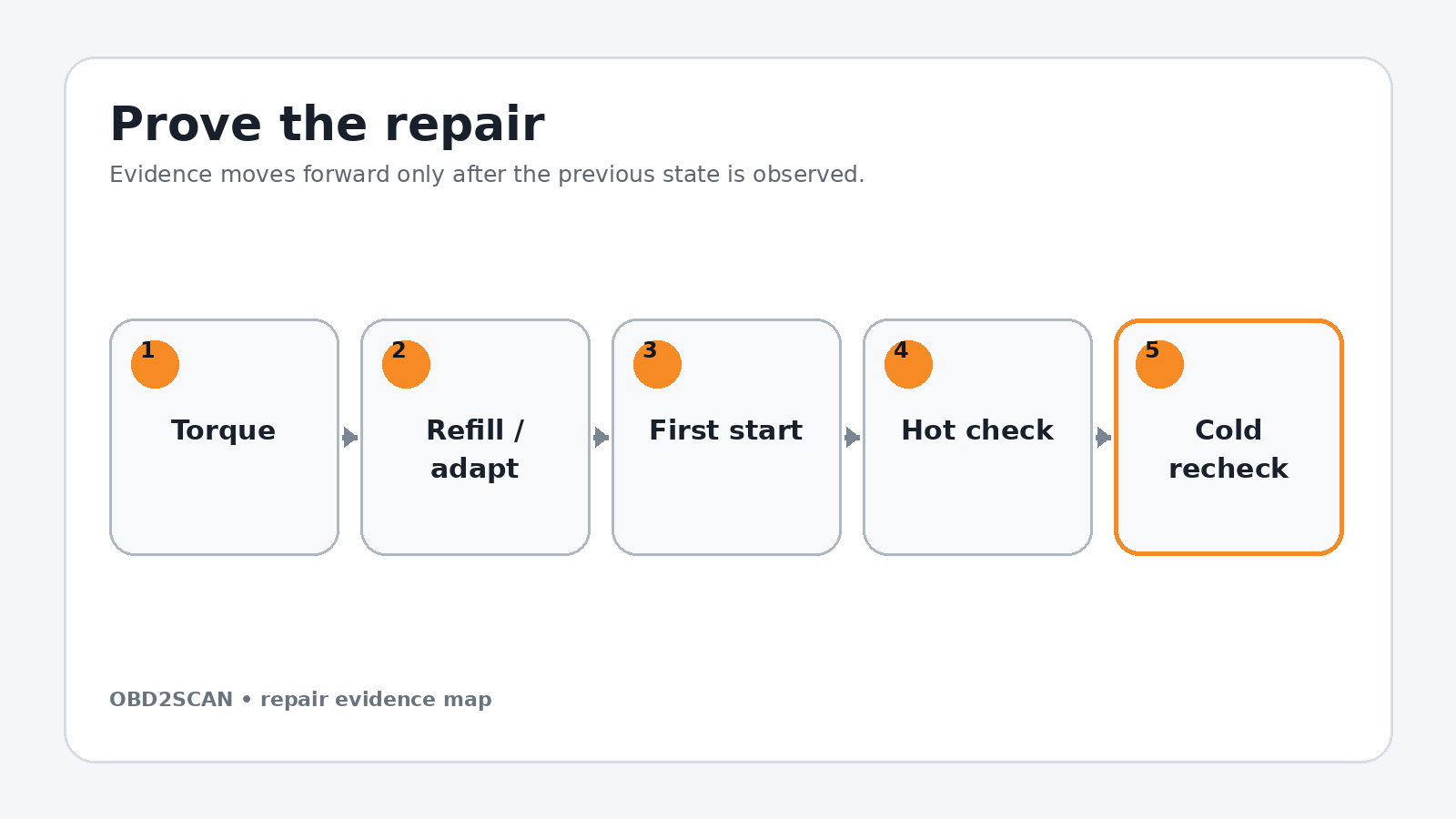
Before road speed, press the brake pedal, steer lock-to-lock and creep over a small surface change while listening. Stop for a clunk, changing brake pedal, ABS warning or tire contact. On the road, build speed gradually and confirm straight tracking, centered steering and no vibration.
After roughly 10 miles, recheck wheel-bolt torque and visually inspect all joints. Do not retorque torque-to-yield suspension hardware casually; inspect witness marks and use the prescribed replacement process if movement is suspected. Keep the alignment printout as the objective completion record.
Completion standard: Ride-height final torque, alignment printout, centered wheel and quiet road test.
Common ways this repair goes wrong
- Diagnosing every front clunk as a full control-arm set
- Heating a seized pinch bolt without protecting aluminum, hoses and boots
- Letting the knuckle hang from the brake hose or CV joint
- Final-torquing bonded bushings at full droop
- Mixing torque locations in a multi-link suspension
- Skipping the post-repair alignment and steering-center check
A repair is not improved by clearing a code, adding sealant, tightening beyond specification or skipping a blocked step. When a checkpoint fails, return to the last verified state and correct the cause before more parts are installed.
Exact repair checklist
- VIN, engine/chassis code and installed component revision match the planned procedure.
- The failed component or interface was proven before disassembly; the before-state is saved.
- All seals, fluids, required new hardware and special tools are present before access is opened.
- Connectors, hoses, fastener lengths, routing and timing/alignment references are photographed and labeled.
- Open fuel, oil, coolant, intake or refrigerant interfaces are protected and every plug is counted.
- Replacement parts seat without force; every structural or sealing fastener starts by hand.
- Final torque, angle, sequence and ride-height/temperature conditions match current service data.
- All fluids, bleed routines, adaptations or calibrations required by the exact vehicle are complete.
- First start passes the listed stop rules; the repaired area is checked before trim or shields hide it.
- The original symptom is repeated hot and cold, the final scan is saved and the next-morning recheck passes.
Minimum record to retain
Retain the VIN, engine or chassis code, before-scan, symptom conditions, disassembly photos, connector labels, fastener map, service-data revision and every measured value. Record the exact fluid specification and quantity added, all adaptations or bleed routines completed, the first-start observations and a cold recheck. A later technician should be able to tell what was directly observed, what was replaced and which same-condition test proved the repair without relying on the invoice description.
- The upper pinch bolt can dominate labor and may require the job to stop for knuckle-safe removal.
- Bonded-rubber bushing fasteners are finally tightened at simulated ride height.
- The documented forward-lower ball-joint nut is 110 Nm and wheel bolts 120 Nm.
- A four-wheel alignment is required after geometry-affecting arm replacement.
This workflow is marked completed only when its stated repair and post-repair checks are represented. It does not certify an unseen vehicle, replace current service information or convert a different engine/chassis variant into the documented configuration.






Comments 0
Questions, fixes, and real-world diagnostic notes from readers.
Be the first to share a diagnostic result or ask a follow-up question.