
Mercedes W204/W212 Alternator and Belt: Prove Charging, Then Replace

Bottom line: A complete M272/M273-era Mercedes charging repair that separates battery, regulator and alternator faults, isolates the B+ cable, renews the belt drive and verifies output under load.
Can you know how to repair it from this page? Yes—after the vehicle and failure match. The article identifies the staged parts and tools, access layers, removal and installation sequence, torque gates, fluid or adaptation work, first-start stop rules and the same-condition test that closes the job.
In this case
- Repair at a glance
- Confirm the repair before disassembly
- Parts, tools, and consumables to stage
- Preparation and safety boundary
- Remove the access layers without losing the map
- Exact repair sequence
- Reassembly and torque control
- Fluids, adaptations, and first start
- Prove the repair under the original condition
- Common ways this repair goes wrong
- Exact repair checklist
- Minimum record to retain
Repair at a glance
| Field | Repair detail |
|---|---|
| Applies to | Documented M272/M273 W204/W212-related layout after engine/VIN confirmation |
| Repair trigger | Alternator or regulator proven by output, command and voltage-drop tests |
| Parts | Correct alternator or regulator, belt, idlers/tensioner and combi-valve gasket as needed |
| Time / difficulty | About two hours when access and fasteners cooperate |
| Stop point | B+ cable remains live, battery is damaged, or a pulley is seized |
| Proof complete | Stable charging at idle and load, correct belt tracking, no warning after drive cycle |
Confirm the repair before disassembly
Charge and test the battery first. Measure open-circuit condition, cranking voltage and charging voltage at the battery, then compare voltage at the alternator B+ and engine ground under load. A failed battery, open fusible link, high-resistance cable or missing alternator command can imitate a bad alternator.
Use scan data and a current clamp where available. If output is low, determine whether the regulator can be serviced separately and whether the rotor slip rings are still suitable. The battery-warning diagnostic path keeps the charging source, storage device and distribution path from being replaced as one guess.
Do not continue when: B+ cable remains live, battery is damaged, or a pulley is seized.
Parts, tools, and consumables to stage
Stage the complete job before access is opened. Part numbers, seals, bolt-reuse rules and fluid specifications must be matched to the VIN, engine or chassis code; a familiar model name is not precise enough.
| Parts and consumables | Tools and support equipment |
|---|---|
| • Engine/VIN-correct alternator or voltage regulator after testing • Correct-length serpentine belt • Tensioner and idlers that fail play/noise inspection • Combi-valve gasket if its sealing joint is opened • Protective B+ terminal cap or nut if damaged • Battery only if it independently fails capacity and conductance testing | • E10, E12 and E14 sockets • 10, 13 and 17 mm tools • Flex-head ratchets, extensions and breaker bar • T20 bit for regulator-only service • 5 mm locking pin for the tensioner • Torque wrench and belt-routing reference • Digital multimeter, current clamp and scan tool |
Preparation and safety boundary
Save codes and settings, switch ignition off, remove the key and wait for modules to settle. Remove the cabin-filter airbox to reach the battery, loosen the negative terminal with a 10 mm tool and isolate the cable so it cannot spring back. Verify the alternator B+ terminal is no longer live before a wrench approaches it.
Do not cut a reusable belt merely for convenience. Use the tensioner to unload it unless the belt is already condemned and the procedure explicitly benefits from removal. Keep the locking pin fully seated and hands out of the spring path. A cracked tensioner stop or partial pin engagement can release stored energy.
Remove the access layers without losing the map
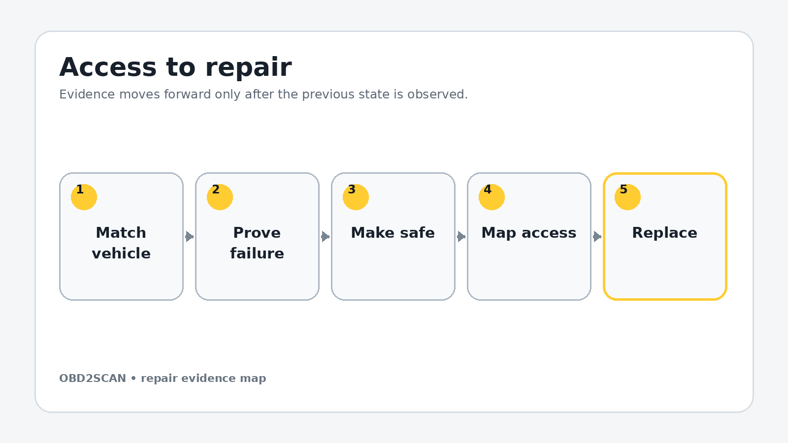
Remove the front engine cover and passenger-side intake snorkel. Photograph belt routing. Rotate the tensioner counter-clockwise with the 17 mm tool, install the 5 mm locking pin and remove the belt. Remove the water-pump idler with E12 and the lower idler with E14 as required for clearance.
Remove the tensioner’s two E14 mounting bolts. Spin each pulley by hand; replace any with roughness, noise, play or heat discoloration. Move the combi valve by removing its three E10 fasteners, releasing the large air hose and sliding the changeover valve from its bracket while leaving sound vacuum lines undamaged.
Use separate trays for each access layer, label connectors by destination and photograph every hidden hose before it moves. Mark fastener length and location on a drawn component outline. Reassembly should follow a map created during removal, not memory or wire reach.
Exact repair sequence
Complete the following sequence in order. A bold lead identifies the action; the remaining sentence states the checkpoint that must be true before the next action begins.
- Free the alternator harness. Release the spring clip or replace its cable tie without nicking the harness. Note the routing that keeps the wires away from the belt.
- Break loose the upper alternator bolts. Use E12 and short extensions. Leave one threaded a few turns until the lower fasteners are controlled.
- Reach the two lower bolts. Use the correct E12/10 mm access from above or below after removing shields. Support the alternator before the final bolt exits.
- Rotate the alternator rearward. Create access without pulling on the cable. Disconnect the regulator plug by its lock.
- Remove the B+ connection. Lift the protective cap, remove the 13 mm nut and move the now-dead cable aside without bending the terminal eye.
- Choose regulator or complete-unit repair. For a proven regulator-only fault, place the alternator pulley-down, remove the T20 rear cover and three regulator fasteners, then inspect brush and slip-ring condition.
- Install the regulator carefully. Retract the brushes with a pick only as designed, seat the regulator squarely and reinstall its T20 fasteners and cover. If bearings, windings, pulley or slip rings are faulty, use the correct complete alternator instead.
- Reconnect B+ before mounting hides it. Position the alternator rear-up, hand-start the B+ nut, tighten to current service data, close the protective cap and reconnect the regulator plug.
- Install all four alternator bolts by hand. Seat the unit against the timing cover and tighten evenly with E12/10 mm tools to the engine-specific values. Restore the harness clip.
- Refit the combi valve. Use a sound gasket, start all three E10 fasteners by hand and reconnect its hose, vacuum/changeover valve and bracket.
- Install tensioner and idlers. Start fasteners by hand. The documented idler value is 25 Nm; obtain the engine-specific tensioner and alternator values before final tightening.
- Route the new belt exactly. Confirm the smooth side and ribbed side contact the correct pulleys. Hold the tensioner, remove the pin slowly and inspect every rib around the full route.
Reassembly and torque control
Reconnect the battery negative only after the B+ cap, alternator plug, harness routing and belt seating pass inspection. Refit the battery airbox and intake snorkel, but leave the decorative engine cover off for the first running observation.
Start with the battery and charging baseline so before-and-after values use the same measurement points. A dashboard voltage display is useful, but a meter at the battery and alternator reveals cable drop that a single displayed number can hide.
| Fastener or setting | Documented value | Applicability gate |
|---|---|---|
| Water-pump and lower idler fasteners | 25 Nm | Documented M272/M273-era layout |
| Alternator mounting | Use current engine/VIN data | Four fasteners; do not infer from tool size |
| Alternator B+ terminal | Use current alternator data | Protect terminal against rotation |
| Tensioner and combi valve | Use current engine/VIN data | Confirm gasket and bolt type |
Torque boundary: Values in this table belong to the documented configuration. Check current VIN/engine-specific service data, bolt material, replacement rule and torque sequence before applying them.
Fluids, adaptations, and first start
Switch ignition on and confirm normal warning-lamp behavior, then start. Watch the belt from a safe distance: every rib must remain centered and the tensioner should not hammer through excessive travel. Shut down for chirping, belt walk, smoke or a battery lead heating rapidly.
Measure voltage at the battery at idle and under electrical load, then measure alternator B+ to battery-positive and case to battery-negative voltage drop. Smart charging varies; compare command, current and battery state rather than declaring one universal voltage mandatory. Around 13.6 V was the documented post-repair observation, not a specification for every condition.
Prove the repair under the original condition
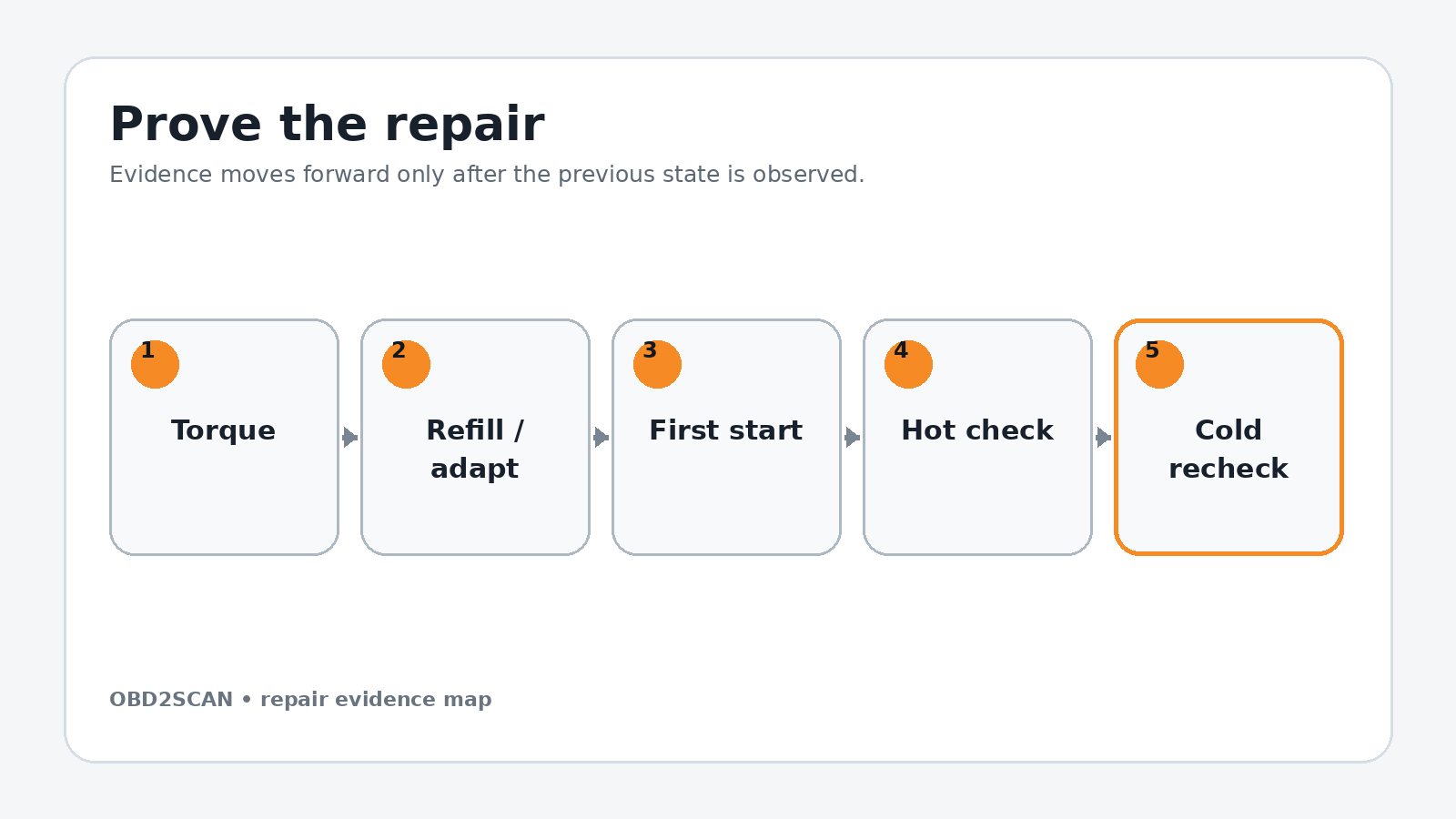
Load the headlights, blower and rear defogger while monitoring voltage and current. Scan for generator communication, undervoltage and lost-initialization faults. Restore window, roof or steering-angle initialization only as the vehicle requires after battery disconnection.
After a road drive, shut down and inspect belt dust, pulley alignment and terminal temperature. Restart hot and confirm the warning stays off. The repair is complete when the charging system meets command under load, cable drops are acceptable and the belt drive remains quiet and centered.
Completion standard: Stable charging at idle and load, correct belt tracking, no warning after drive cycle.
Common ways this repair goes wrong
- Replacing the alternator before testing the battery, cables and control command
- Leaving the B+ cable live
- Confusing a worn regulator with failed bearings or slip rings
- Routing the belt from memory
- Releasing a partially engaged tensioner lock
- Using one unloaded voltage number as the entire repair verification
A repair is not improved by clearing a code, adding sealant, tightening beyond specification or skipping a blocked step. When a checkpoint fails, return to the last verified state and correct the cause before more parts are installed.
Exact repair checklist
- VIN, engine/chassis code and installed component revision match the planned procedure.
- The failed component or interface was proven before disassembly; the before-state is saved.
- All seals, fluids, required new hardware and special tools are present before access is opened.
- Connectors, hoses, fastener lengths, routing and timing/alignment references are photographed and labeled.
- Open fuel, oil, coolant, intake or refrigerant interfaces are protected and every plug is counted.
- Replacement parts seat without force; every structural or sealing fastener starts by hand.
- Final torque, angle, sequence and ride-height/temperature conditions match current service data.
- All fluids, bleed routines, adaptations or calibrations required by the exact vehicle are complete.
- First start passes the listed stop rules; the repaired area is checked before trim or shields hide it.
- The original symptom is repeated hot and cold, the final scan is saved and the next-morning recheck passes.
Minimum record to retain
Retain the VIN, engine or chassis code, before-scan, symptom conditions, disassembly photos, connector labels, fastener map, service-data revision and every measured value. Record the exact fluid specification and quantity added, all adaptations or bleed routines completed, the first-start observations and a cold recheck. A later technician should be able to tell what was directly observed, what was replaced and which same-condition test proved the repair without relying on the invoice description.
- The alternator B+ lead stays live until the battery negative is isolated.
- Four alternator fasteners and the rear electrical connections are accessed after the combi valve moves.
- Documented idler fasteners are 25 Nm.
- Charging voltage and belt tracking are checked after installation.
This workflow is marked completed only when its stated repair and post-repair checks are represented. It does not certify an unseen vehicle, replace current service information or convert a different engine/chassis variant into the documented configuration.








Comments 0
Questions, fixes, and real-world diagnostic notes from readers.
Be the first to share a diagnostic result or ask a follow-up question.