
How to Install and Use the MRCARTOOL M50 Inclinometer

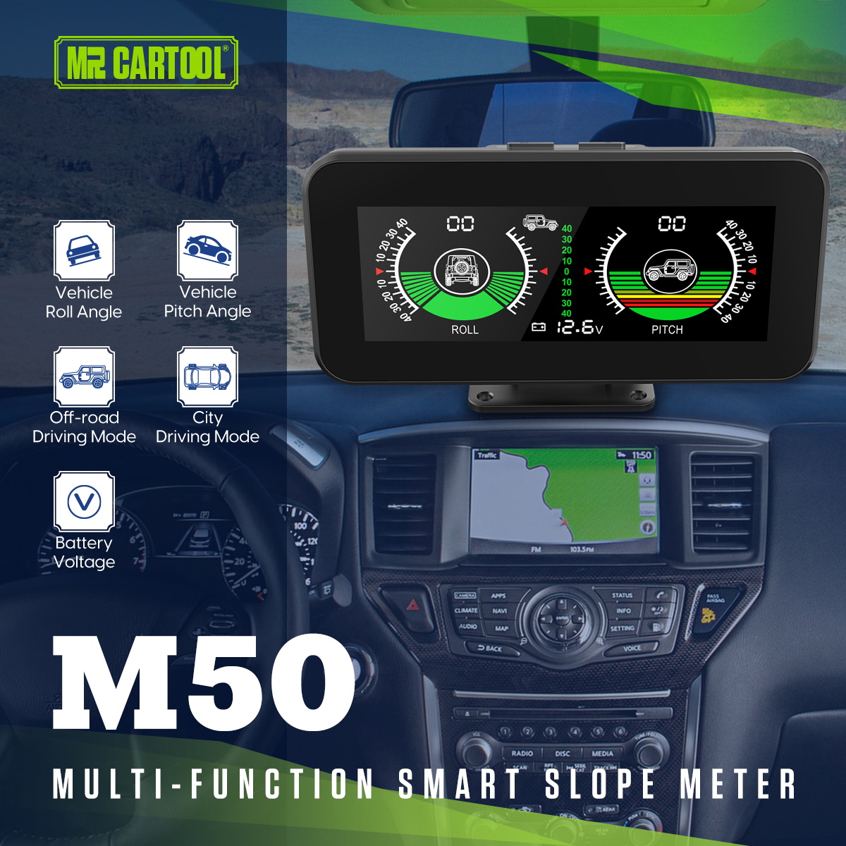
The MRCARTOOL M50 inclinometer displays vehicle pitch, roll and supply voltage on a dashboard screen with city and off-road modes. Good readings depend more on installation than on button pressing: the bracket must be rigid, the display must align with the vehicle centerline, and zero must be set only when the vehicle is on a verified level surface at normal ride height. The stated ±40° pitch/roll span is the instrument range—not a safe operating angle for any vehicle.
Quick answer: Dry-fit M50 outside the road-view, instrument and airbag zones. Align its face square to the vehicle and make the bracket rigid. Power it with the supplied cigarette-lighter cable or have a qualified installer connect the supplied hardwire lead to a correctly fused, vehicle-approved switched circuit; input must remain within DC 10–30 V. Park on a verified level surface, load the vehicle normally, then short-press On/Off to reset pitch and roll. Hold the function-select button for 5 seconds to enter city/off-road mode selection, choose the required mode, then hold for another 5 seconds to save. Short-press function select to adjust brightness. Verify zero, positive/negative direction and voltage before relying on trends.
In this guide
Understand the M50 and its limits
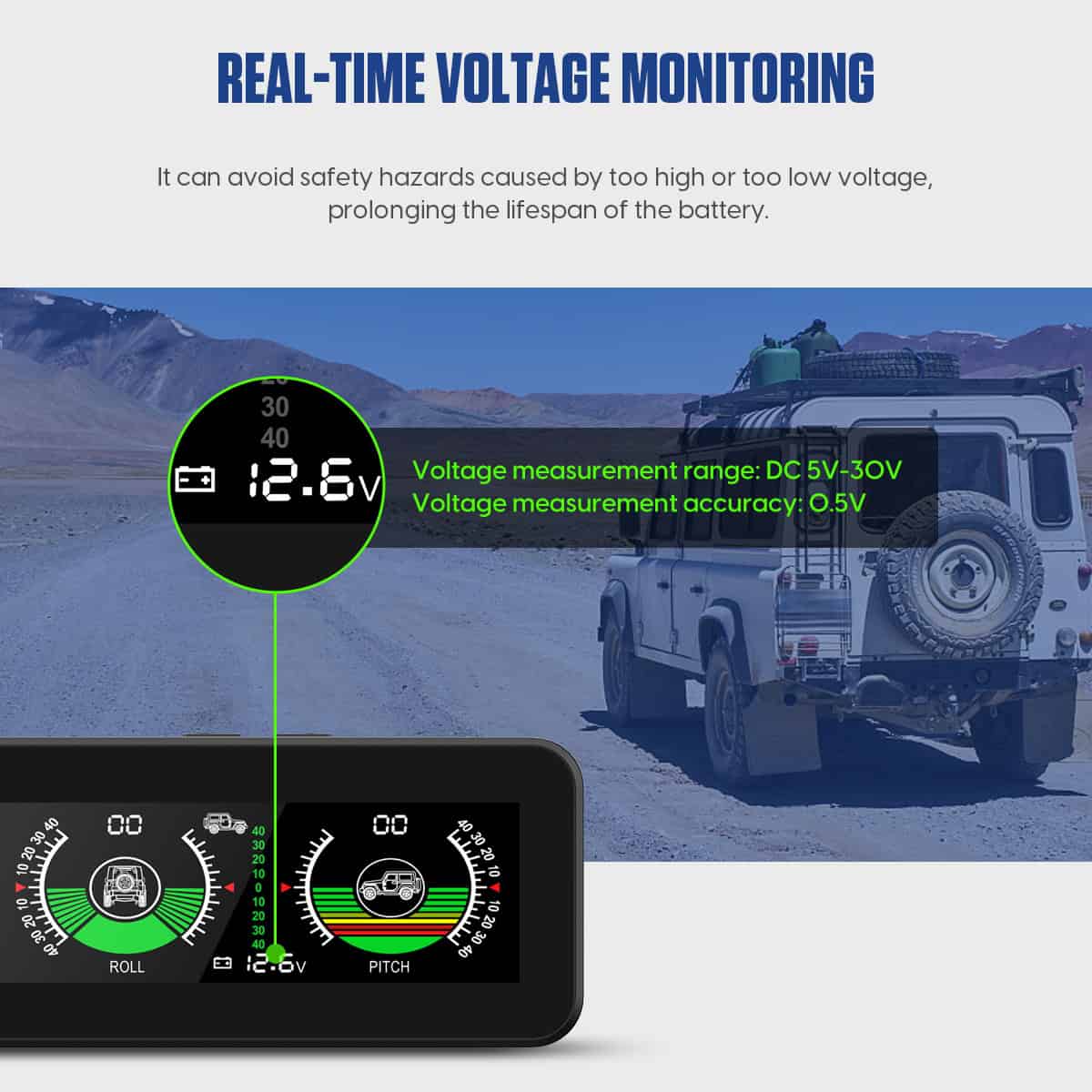
The current exact product page specifies DC 10–30 V input, a DC 5–30 V measurement range with 0.5 V stated accuracy, a -40°C to 80°C operating-temperature range and -40° to +40° pitch and roll display spans. The unit measures 127 × 25 × 60 mm and weighs 230 g. The package includes a bracket, cigarette-lighter cable, refitted hardwire cable and printed manual.
The M50 uses a multi-axis gyroscope to report the instrument’s orientation. It does not measure tire contact, available traction, center of gravity, side-slope stability or the terrain beyond the vehicle. Vehicle suspension movement, dashboard flex, cargo, tire pressure and mounting alignment can all change the reading. A number within ±40° does not mean the vehicle can safely drive at that angle; the vehicle manufacturer, conditions and trained driver control the decision.
Never drive toward an alarm threshold to test it. A rollover can occur before the M50 display limit and without a perfect static relationship between dashboard angle and terrain. Keep speeds low where appropriate, follow vehicle and route limits, use a spotter when needed, wear restraints and turn around before a slope becomes uncertain. The M50 is supplementary information, not a stability-control system.
Mount and align the display
1. Choose a rigid, unobstructed position
Sit in the normal driving position and dry-fit the M50 low on the dashboard. It must be visible with a short glance without hiding the road, warning lamps or required instruments. Keep the screen and bracket outside steering-wheel and passenger-airbag covers and away from curtain-airbag trim. Check vents, demister airflow, sunlight reflection and passenger visibility. A flexible mat or loose tray is unsuitable because it can tilt independently of the vehicle.

2. Align with the vehicle axes
Center the display face perpendicular to the vehicle’s longitudinal centerline: the M50 left/right roll axis should match the vehicle left/right axis, and its front/rear pitch axis should match the vehicle centerline. Use fixed cabin references rather than judging the screen alone. A unit rotated on the dashboard mixes pitch and roll; braking can then appear partly as side angle and cornering partly as nose-up or nose-down.
3. Lock the bracket before zeroing
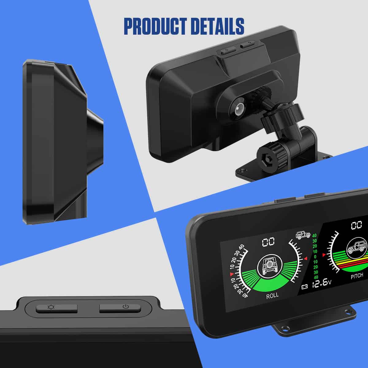
Adjust the holder for a readable screen, tighten every joint and mark the bracket position if it can be disturbed. Press gently in several directions; the indicated angle should not change because of bracket play. Do not cut the housing, expose its circuit board or install it where trim modifications compromise airbags or structure. If permanent attachment needs drilling or trim removal, use vehicle information and a qualified installer.
Connect power safely
4. Use the plug-in cable for the first setup
The cigarette-lighter cable is the reversible way to validate placement and operation. Confirm the outlet voltage is within DC 10–30 V and whether the outlet switches off with the vehicle. Route the cable along fixed trim, away from pedals, steering, shifter, seat tracks, sharp edges and airbag seams. Provide strain relief so vibration cannot tug the rear connector or rotate the bracket.
5. Hardwire only to an approved protected circuit
The supplied refitted power lead does not by itself identify a safe vehicle connection. A qualified installer should use the correct circuit diagram, fuse protection, polarity, conductor protection and grounding method for the vehicle. Use a circuit whose operating and sleep behavior matches the installation plan. Never probe or tap an unknown wire, safety-restraint circuit, network wire or high-voltage system. Verify key-off current and shutdown so the accessory cannot discharge the battery.
The M50 voltage field observes the voltage presented at its own input. Wiring resistance, socket condition and circuit loading can make that value differ from a calibrated measurement directly at the battery. Use it for trends and warning context; diagnose a charging fault with a suitable meter and the vehicle test procedure.
Zero pitch and roll correctly
6. Prepare a true reference condition
Park on a known level, firm surface—not merely a place that looks flat. Set normal tire pressures and ride height, unload unusual cargo and let self-leveling suspension settle if equipped. Point the wheels straight, close doors and keep people from entering or leaning on the vehicle during zeroing. The M50 and bracket should be at their normal operating temperature and final installed position.
7. Short-press On/Off to reset both angles
With the vehicle stationary on the verified reference, short-press the On/Off button. The exact product instructions say this resets roll and pitch. Confirm both fields return to their baseline. Do not press the reset while parked on a cambered road, ramp, trail obstacle or tilted campsite; that would redefine the current slope as zero and make later readings misleading.
8. Verify direction instead of assuming it
After zeroing, move to a mild, known incline under controlled conditions or gently load one side while stationary according to a safe workshop method. Confirm the nose-up/nose-down and left/right indicators change in the expected direction and return near zero on the reference surface. If axes appear mixed, realign the bracket rather than using mental correction while driving.
Choose city/off-road mode and brightness
9. Enter and save driving mode
The product page gives an exact timing sequence: press and hold the function-select button for 5 seconds to enter the city/off-road selection interface. Select the desired mode using the labels shown on the exact display, then press and hold for 5 seconds again to save. Do this while parked. After saving, cycle power and confirm the selected mode remains visible before beginning a trip.
The page does not define every internal difference between city and off-road modes, so do not assume one changes the physical sensor range or makes steeper driving safe. Treat the selection as a display/alarm profile and verify its visible behavior. If an alarm value or symbol differs from the current unit, use the supplied printed manual rather than a menu sequence from another M-series model.
10. Set brightness
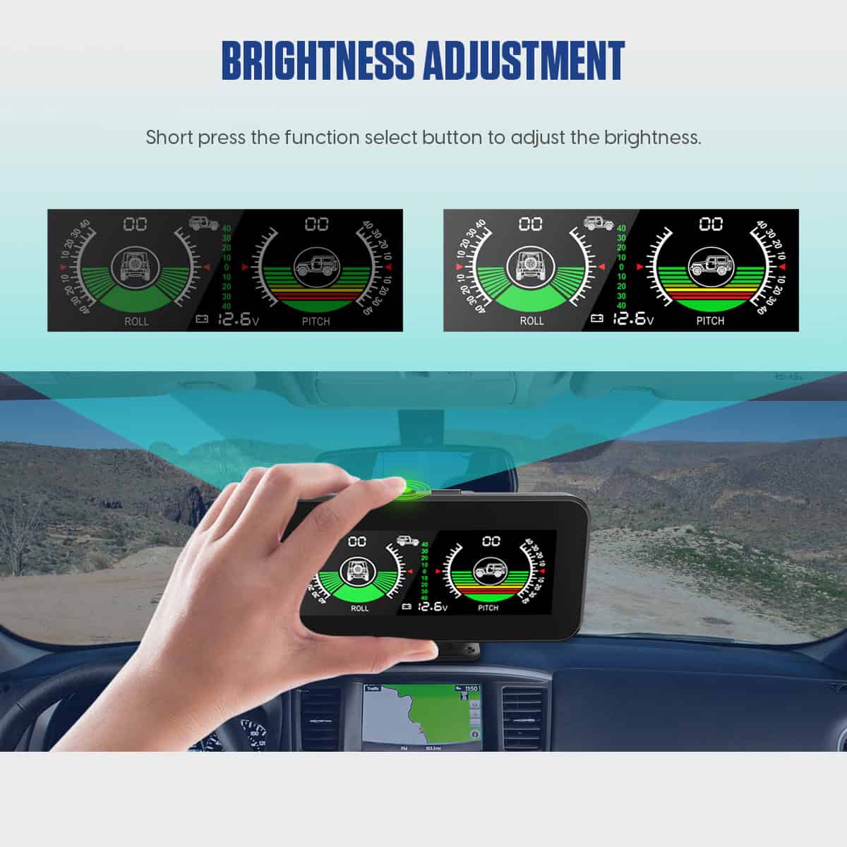
Short-press the function-select button to adjust brightness. Check the selected level in daylight, shadow and darkness. The screen should be readable with a brief glance but should not create windshield reflection or reduce night vision. Stop before adjusting it; repeated top-button presses while moving divert attention and can disturb the bracket.
Verify readings and interpret alarms
11. Compare zero and repeatability
Return to the same level reference after the first drive. Pitch and roll should return close to the established baseline. A consistent offset suggests bracket movement, vehicle loading, suspension change or a zeroing issue. Record the mounting position and baseline if the readings matter operationally. Repeat after tire, suspension, roof-load or cargo changes because those factors can alter body attitude.
12. Treat beeps as early prompts
The exact page says M50 beeps when pitch or roll exceeds its default alarm value, but it does not publish the value. Do not reverse-engineer it by approaching rollover risk. If an alarm sounds in use, reduce inputs, stop where safe and reassess terrain, vehicle position and load. An alarm that seems early can still be useful; an alarm that has not sounded is not proof of stability.
Dynamic readings during braking, acceleration, cornering and bumps include body motion and sensor response, not just ground slope. Use a stable low-speed or stopped reading when judging a static incline. Never stare at the display through a maneuver. A trained spotter with a clear view of wheels and obstacles can provide information the dashboard cannot.
Troubleshooting
| Symptom | Check first |
|---|---|
| No power | Outlet state, DC 10–30 V supply, fuse, polarity, cable seating and connector damage |
| Angles not zero on level ground | Surface verification, vehicle load, tire pressure, bracket play and correct reset |
| Pitch changes during turns | Display may be rotated relative to the vehicle centerline |
| Readings jump over bumps | Dynamic body motion and loose mount; evaluate stable conditions |
| Voltage differs from battery meter | Socket voltage drop, wiring resistance, circuit load and meter test location |
| Mode will not save | Use the full 5-second enter and 5-second save holds while parked |
| Screen reflects at night | Short-press brightness adjustment and reconsider screen angle |
| Alarm meaning is unclear | Stop safely; inspect pitch, roll, mount, terrain and exact printed manual |
Final M50 checklist
- Rigid legal mount outside sight-line, instrument, vent and airbag zones
- Display square with vehicle centerline and bracket joints locked
- Cable protected from controls, pedals, seat tracks, heat, edges and airbags
- Plug-in or hardwired supply verified within DC 10–30 V
- Hardwire circuit correctly fused and key-off current checked
- Vehicle at normal load and tire pressure on a verified level surface
- Pitch and roll reset only on that reference surface
- Axis directions verified and baseline repeatable
- City or off-road mode entered with 5-second hold and saved with 5-second hold
- Brightness readable without glare
- Voltage treated as an input trend, not standalone charging diagnosis
- ±40° display range never treated as a vehicle safety limit
The M50 becomes useful when its physical reference is trustworthy. Mount it rigidly and square, power it through a protected vehicle-approved path, zero it only on a known level surface and verify both axes. Use city/off-road mode and brightness as display choices, voltage as a trend and beeps as prompts to stop and reassess. The driver, vehicle limits, traction, load and terrain still determine what is safe.











Comments 0
Questions, fixes, and real-world diagnostic notes from readers.
Be the first to share a diagnostic result or ask a follow-up question.