
BMW i3 Drivetrain Error and No READY: The ‘Crash’ Code Was a Broken 12-Volt Wire

No Ready? Follow Terminal 30C
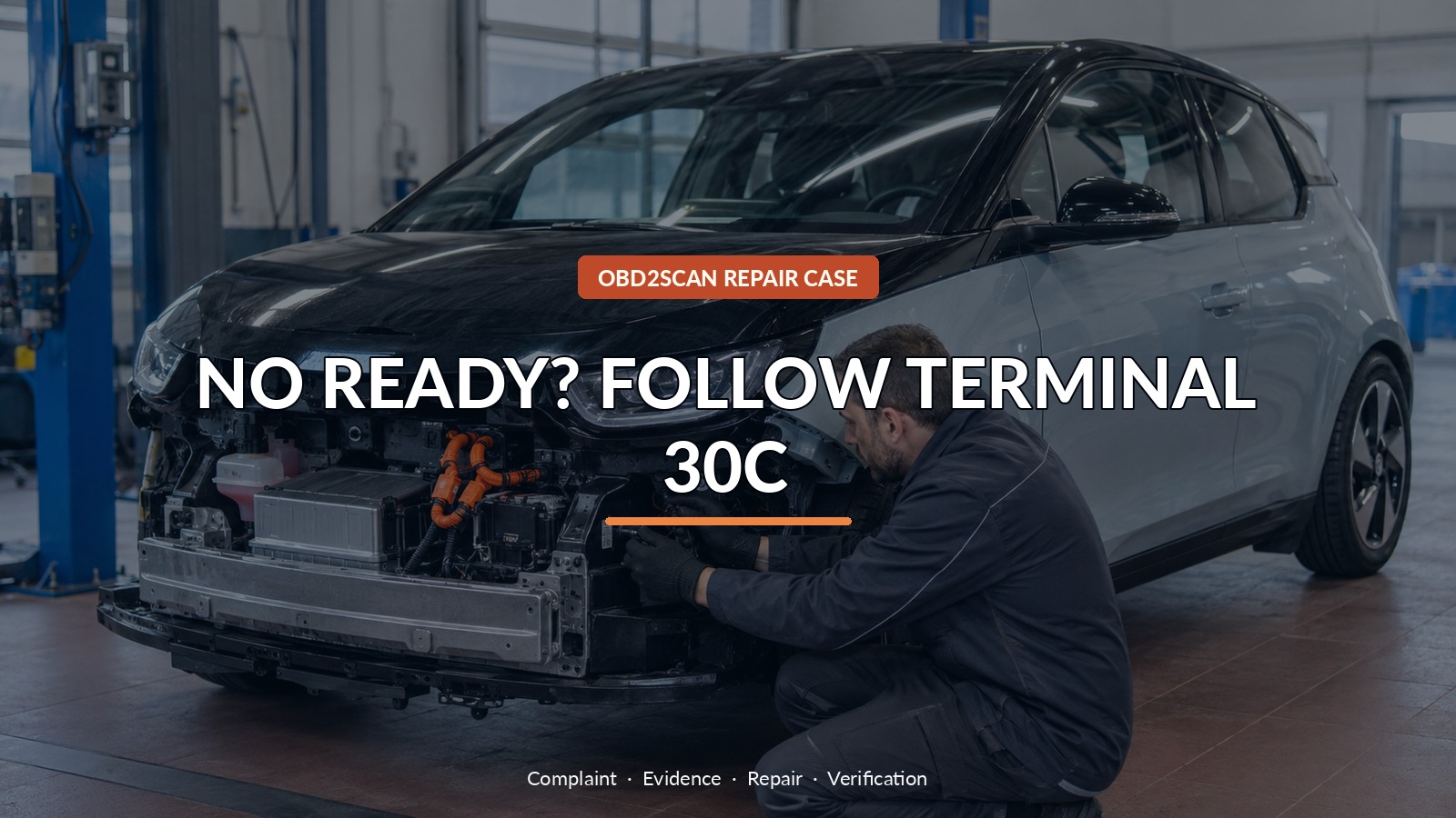
A BMW i3 that will not enter READY can display language dramatic enough to make a traction battery or crash shutdown feel inevitable. That was not the result in this documented repair. The car had lost a small Terminal 30C supply through one broken 12-volt wire. Locating and repairing that conductor restored charging and READY mode without replacing a high-voltage component.
The right first instrument was a meter and scope, used on the low-voltage side after the wiring path was known. A AUTOOL DM303 can support that kind of accessible voltage, continuity, and signal work. DM303 can support accessible low-voltage, continuity and waveform checks after BMW wiring information identifies the circuit; it cannot make the high-voltage system safe, interpret BMW test plans or prove where a concealed wire is open from one reading.
This is one car’s evidence trail, not a claim that a Terminal 30C wire explains every i3 drivetrain warning. The useful lesson is the order: preserve the fault state, separate high-voltage safety from low-voltage diagnosis, prove where power stops, and verify the same functions that originally failed.
Quick answer: A no-READY i3 does not prove high-voltage battery failure. In this case, point-to-point testing found an open Terminal 30C wire; repairing it restored charging and READY.
In this guide
- Start with the no-READY condition, not the worst code
- Separate the 12-volt and high-voltage jobs
- Build a power-distribution map from the wiring diagram
- Use continuity to shrink the open circuit
- Expose the harness only where the evidence points
- Repair the conductor without creating a second weakness
- Clear faults only after restoring the feed
- Verify charging and READY mode under the original conditions
Start with the no-READY condition, not the worst code
The i3’s customer-facing message described a drivetrain problem, but the actual complaint was more specific: the vehicle would not switch to READY. Begin there. Record whether the charge port responds, whether the selector can engage a drive position, the condition of the 12-volt battery, and every control-unit fault before clearing anything. A crash-related description is a clue about why a controller inhibited operation; it is not physical proof that the car was in a collision or that a high-voltage pyrofuse has opened. On an EV, severe wording should increase discipline, not accelerate parts ordering.
Separate the 12-volt and high-voltage jobs
High-voltage isolation belongs to trained personnel with the correct PPE and current BMW procedure. Low-voltage diagnosis is still not casual, but it answers a different question. In this case, the missing condition was a 12-volt feed used by the safety and control chain. Establish a stable 12-volt baseline first and confirm whether the relevant controller wakes up. Do not probe orange connectors or defeat an interlock to chase a low-voltage fault. If the service plan requires de-energizing the high-voltage system, stop and complete that process before accessing any shared area.
Build a power-distribution map from the wiring diagram
A wiring diagram turns a vague drivetrain warning into a list of junctions, connectors, fuses, and branches. Mark where Terminal 30C originates, where it passes beneath the battery carrier, and where it reaches the high-voltage safety connector. Then measure at accessible points from the load back toward the source. The purpose is not to collect many voltages; it is to find the last point with a correct supply and the first point without one. Check the ground reference as carefully as the feed so a poor test ground does not imitate an open conductor.
Use continuity to shrink the open circuit
With the battery disconnected through the approved process, continuity can narrow the failed section. Test short segments instead of one long end-to-end path whenever connectors allow it. Flex the harness gently while observing the reading, because a fractured strand can make intermittent contact when moved. Continuity is not load capacity: a few surviving strands may beep yet collapse under current. Pair resistance or continuity with an appropriate loaded voltage check. In the documented i3, that combination pointed to an open roughly 50 centimeters from the safety connector, beneath the 12-volt battery carrier.
| Evidence | What it supports | What it does not prove |
|---|---|---|
| No READY plus drivetrain warning | A safety/control condition is inhibiting operation | A failed traction battery |
| Terminal 30C present at source, absent downstream | An open or high-resistance section between points | The exact physical damage location |
| Broken conductor at predicted harness point | A cause matching the electrical measurements | That routing damage has been corrected |
| Charging and READY return after repair | Functional closure under the original complaint | A model-wide common failure |
Expose the harness only where the evidence points
Only then should trim, carrier hardware, or harness wrap be disturbed. Photograph clip locations and evidence of rubbing, tension, water, or previous repair before moving the loom. Open the wrap around the predicted point and inspect each conductor rather than pulling until something separates. Finding a broken wire is the turning evidence because it explains the measured open and the lost controller feed. It also creates a second question: was the conductor cut by a sharp edge, stretched by routing, or damaged during earlier work? Correct the cause as well as the copper.
Repair the conductor without creating a second weakness
Use the conductor gauge, splice method, sealing, strain relief, and routing specified for the circuit. A bulky splice left against the carrier can become the next flex point. After repair, perform a gentle pull check, restore abrasion protection, and secure the loom with its original movement allowance. Before reconnecting everything, confirm the repaired segment has low resistance and no short to adjacent circuits or ground. This is a reliability repair inside a control path; twisting wires together to see whether READY returns would create uncertain resistance and a future roadside failure.
Clear faults only after restoring the feed
Reconnect the low-voltage system and follow BMW’s wake-up and diagnostic sequence. Confirm the Terminal 30C supply at the receiving side before deleting stored faults. Then clear only after saving the original report, cycle the vehicle as directed, and rescan every affected controller. Some secondary communication faults may have been consequences of the missing feed; they should become history once all modules power correctly. A code that immediately returns means the circuit, connector, or controller still needs work. A clear dashboard by itself is not the end of the repair.
Verify charging and READY mode under the original conditions
Close the case by recreating the failed functions: connect a known-good compatible charge source, watch the normal port sequence, allow charging to begin, and then verify that the car enters READY and can select drive under controlled conditions. Repeat a shutdown and wake-up rather than relying on one successful attempt. The documented car charged and drove after the harness repair. Record the repaired location, before-and-after voltage, scan state, charge result, and READY result so the owner has evidence that the frightening warning was traced to a defined low-voltage failure.
The expensive-looking message was real, but its cause was ordinary electricity in an important place. This repair succeeded because the technician did not let the word “drivetrain” skip the power-distribution map. For another i3, the same process may lead elsewhere. The repeatable takeaway is to protect the high-voltage boundary, prove the low-voltage feed point by point, repair the reason the conductor failed, and test charging plus READY before calling the car fixed.








Comments 0
Questions, fixes, and real-world diagnostic notes from readers.
Be the first to share a diagnostic result or ask a follow-up question.