
2015 Mazda3 Lit Every Warning Lamp: A Loose Camera Connector Split the CAN Bus

Every Warning Light? Compare Can At Two Points
The Mazda3 could travel 50 miles or 300 before its tach dropped to zero and nearly every warning lamp appeared. About 40 communication codes followed, and several modules had already been replaced after an earlier collision. The way out was not a better parts list. It was comparing the same network at two places during the failure.
This case needs non-destructive connections at identified junctions so measuring equipment can compare locations without cutting the harness. The AUTOOL 92-Piece Circuit Test Lead Kit can help provide those adapters around a suitable multi-channel scope setup. The 92-piece lead kit can help connect suitable measuring equipment at identified junctions without cutting the harness. It cannot replace a multi-channel scope, supply Mazda topology, decode CAN or justify piercing and unplugging unknown circuits.
CAN High and Low looked different at the front body control module and the instrument-cluster end when communication failed. The front-camera connector was a loop in the bus and was not fully seated. Reseating made both captures match; opening it reproduced the exact warnings, tach dropout and codes. Long road verification remained unavailable.
Quick answer: CAN captures diverged across a loose camera-loop connector; reseating normalized them and opening it reproduced the exact warnings and U-codes.
In this guide
- Forty U-codes need a map, not forty diagnoses
- Use the collision history without blaming it
- Compare CAN at two accessible points
- The signals diverged across the cabin
- A camera connector completed the network loop
- Reseat it and deliberately reproduce the fault
- Restore trim and connector retention
- Keep extended road verification explicitly open
Forty U-codes need a map, not forty diagnoses
Forty U-codes are usually reports about a smaller physical event. Save the entire scan and group codes by who lost whom, when they were set and which network they use. The driver interview supplies the recurrence range, dashboard sequence and ignition-cycle reset. Do not clear the car before that map exists. A large number of codes does not mean a large number of failed modules. Here, the tachometer fell first, warning lamps stayed until a restart, and the event could hide for hundreds of miles—classic reasons to monitor a shared path.
Use the collision history without blaming it
The prior collision on the front side and the replaced ABS, restraint, stop-start and body modules changed probability, but they did not prove workmanship caused the fault. Inspect repaired areas and grounds without turning history into a verdict. A network can be damaged far from the impact, and new modules can be victims of the same open circuit. Use the accident to choose accessible measurement locations and connector checks. Keep every observation labeled as present evidence or background so the repair remains fair and technically defensible.
Compare CAN at two accessible points
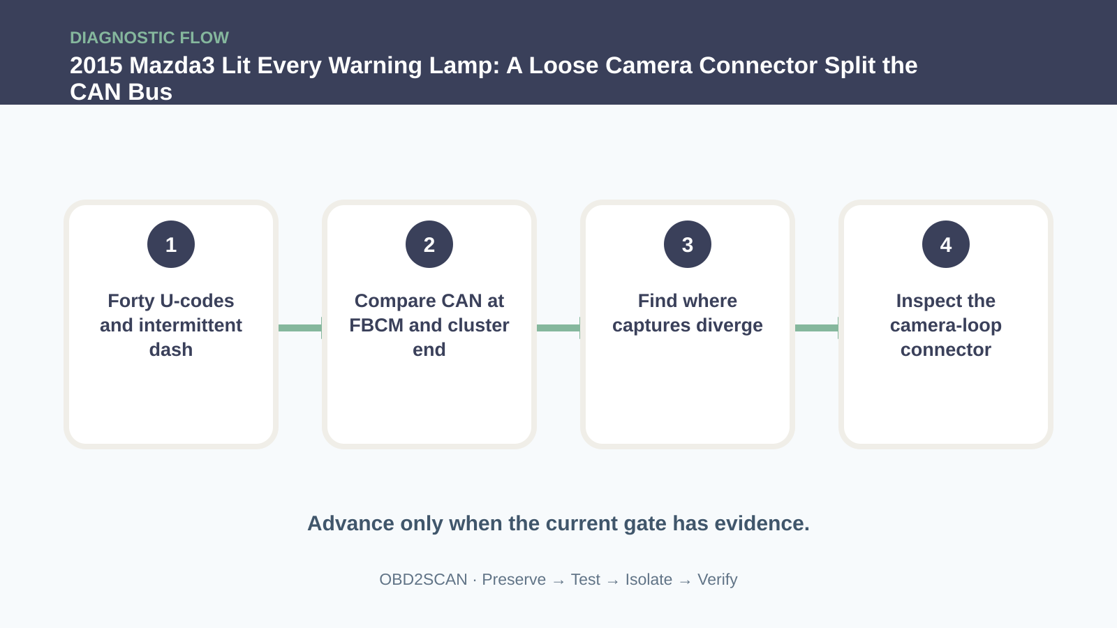
At first the network communicated normally. When the fault finally appeared, the diagnostic connection dropped and the CAN waveform showed abnormal spikes. A single capture near one module confirmed a physical problem but not where it began. The useful plan was to measure CAN High and Low at the front body control module and simultaneously near the instrument cluster, which sat toward the other end of the network. Use service information for pins and access, keep probes secure, and avoid routing test leads where they can interfere with pedals or airbags.
The signals diverged across the cabin
On one continuous bus, corresponding data should arrive at both locations with the expected relationship. During the fault, packets and physical signals no longer matched. That meant the network was being separated or altered between the two points. Resistance checks with the vehicle powered down found no simple short, illustrating why static tests can miss a connector that opens only with body flex or temperature. Location comparison converted “bad CAN” into “bad CAN somewhere between here and there,” a far smaller search area.
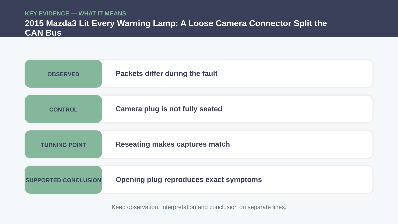
| Evidence | Observation | Meaning |
|---|---|---|
| Complete scan | Roughly 40 communication DTCs | Shared network failure is likely |
| Two-point live capture | Packets diverge during the event | Fault lies between measurement points |
| Camera-loop connector | Plug is not fully seated | Bus can split with movement |
| Connector opened deliberately | Tach, lamps and codes return | Exact symptom is causally reproduced |
A camera connector completed the network loop
The wiring diagram identified four junction areas, including a front-camera connector near the A-pillar. That connector completed a loop in the high-speed bus rather than merely serving an optional camera. It was not fully engaged. A bump, temperature change or body movement could interrupt the path and split the network. This architectural detail is why deleting an apparently unrelated option from a mental map is dangerous. Connector purpose comes from the circuit diagram, not the label printed on the nearby component.
Reseat it and deliberately reproduce the fault
Reseat the connector until its lock is fully engaged, inspect terminal tension and harness strain, and confirm both network captures match again. The original diagnostician then opened the connector deliberately. The waveform deteriorated and the same tach drop, warning lamps and DTCs returned. Reintroducing a fault is powerful causal evidence when it can be done safely and reversibly. Do not shake a moving vehicle or disturb restraint wiring to provoke an intermittent; reproduce at a controlled connector with the vehicle stationary.
Restore trim and connector retention
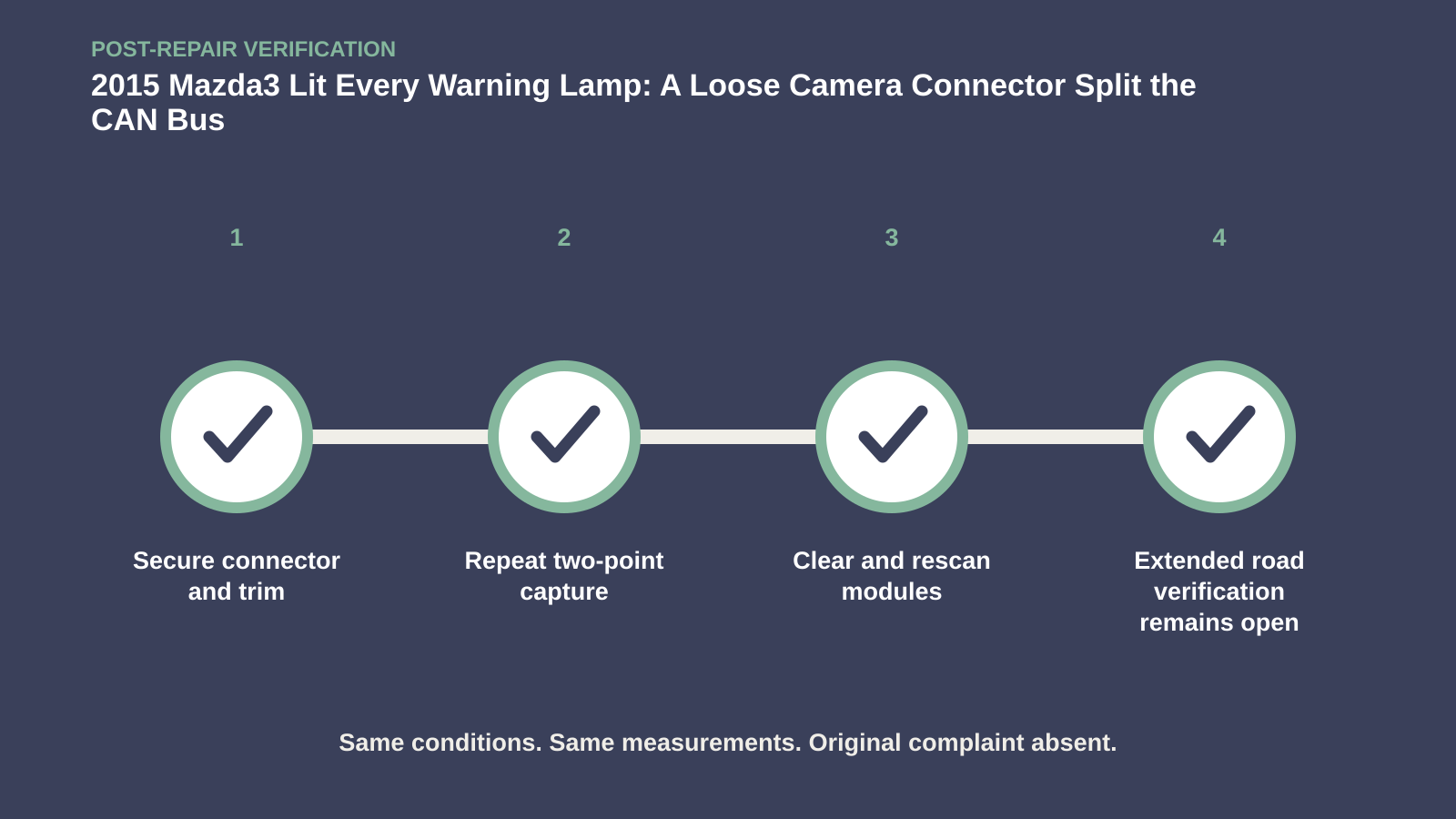
Restore the connector, retention and trim so vibration cannot work it loose again. Clear the codes after retaining the evidence, run a complete scan and compare CAN at both points. Check that the camera and every related module communicate. The published case could not keep the car for extended road testing, so it stops at strong reproduced cause and normalized signals. It would be inaccurate to turn that limitation into a hundreds-of-miles no-return claim. The repair is well supported; endurance verification remains open.
Keep extended road verification explicitly open
A complete handoff would request the customer monitor the original mileage window and return immediately if the tach or lamps recur. Ideally, the shop would road-test beyond the prior 300-mile maximum while logging communication, then rescan without cycling the ignition after any event. Shorter controlled vibration and heat checks can challenge connector retention but are not equivalent to the exact road interval. This explicit boundary makes the article more useful: readers can see what was proved, what was fixed and what evidence was unavailable.
One connector divided the network; two measurement points divided the diagnostic problem. Reseating and deliberate reproduction proved cause, while the missing long drive stayed honestly open.





Comments 0
Questions, fixes, and real-world diagnostic notes from readers.
Be the first to share a diagnostic result or ask a follow-up question.