
Jaguar X-Type P132A Lost Power Under Acceleration: CAN Was Fine, the Turbo Actuator Motor Was Not

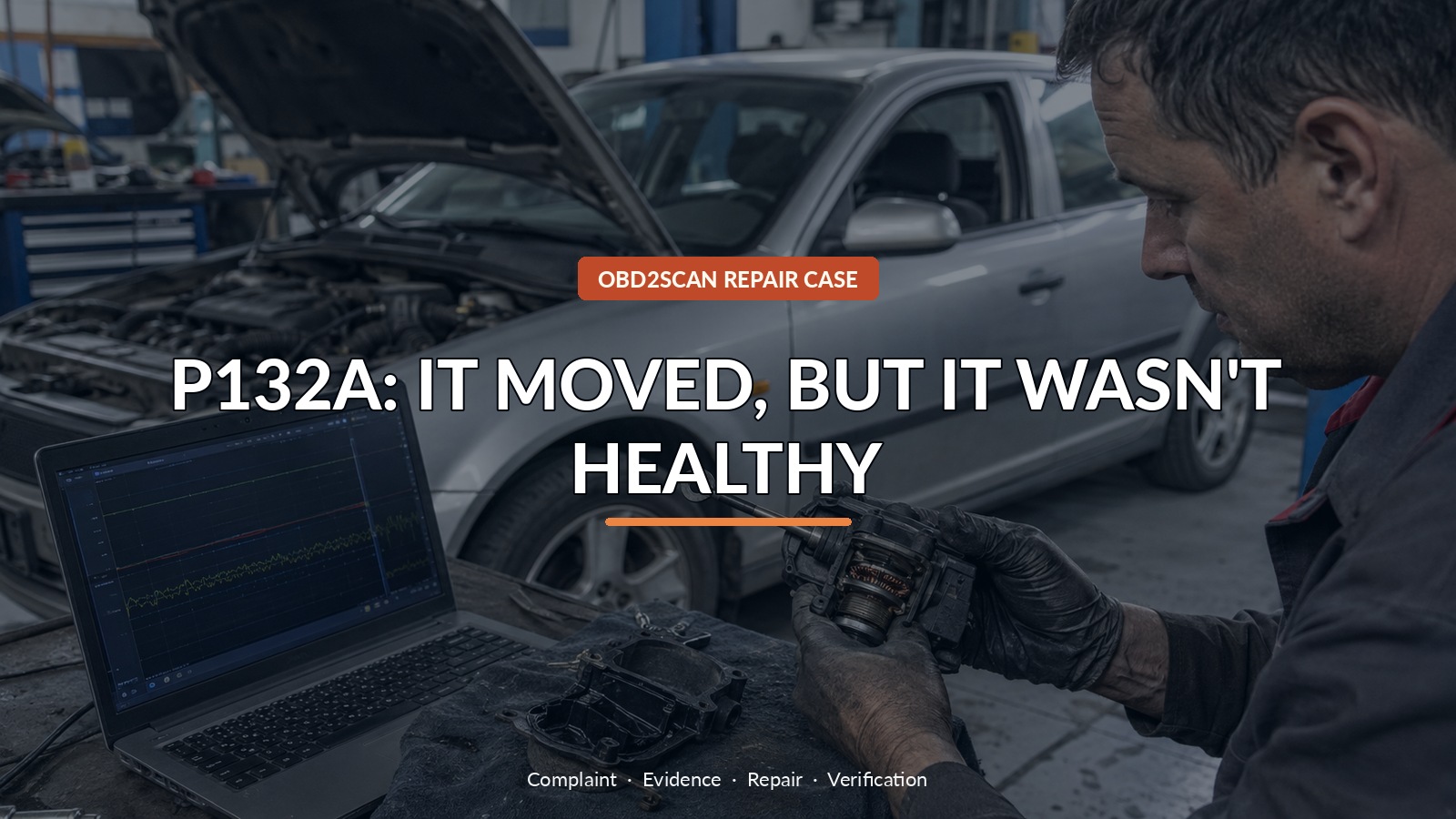
P132A: It Moved, But It Wasn’T Healthy
The Jaguar X-Type lost power abruptly whenever the driver accelerated and recovered only after the ignition was cycled. A split intake hose was found and repaired, but the limp mode returned. Code P132A pointed toward turbo boost control, and the actuator rod could be seen moving. That visual movement looked reassuring. It was also incomplete evidence: the actuator’s CAN communication was healthy while the small motor doing the work was arcing internally.
A meter with automotive waveform capability is useful here only after the actuator pinout is known and the questions are separated. The AUTOOL DM303 can support accessible power, ground and K/CAN checks. DM303 can support accessible power, ground and K/CAN waveform checks after Jaguar data identifies the pins; a handheld trace cannot decode proprietary actuator position, replace simultaneous current capture or certify a cleaned motor as a durable repair.
This case is not an instruction to open and clean every Jaguar turbo actuator. It shows how to distinguish three layers inside one assembly—module communication, motor power and mechanical effort—before choosing a repair.
Quick answer: The turbo actuator moved and communicated, but its motor current was sporadic and peaked near 11 A. Brush and commutator wear caused P132A and limp mode.
In this guide
- Cycling the ignition only reset limp mode
- Repair the obvious intake split but do not stop there
- Read P132A against the actuator architecture
- Separate CAN communication from motor work
- Voltage noise is a clue; current shows the effort
- Open the actuator only after the circuit earns it
- Use cleaning as confirmation, not a durability promise
- Repeat acceleration and compare the current trace
Cycling the ignition only reset limp mode
The first road test reproduced a sharp transition into limp mode. Cycling the ignition restored normal power until the next acceleration. That reset behavior did not identify the failed part; it showed that the PCM deliberately suspended boost control after detecting something implausible. The return of P132A without the earlier EGR code moved the EGR valve down the list. The repaired intake split also stayed repaired, so the investigation continued instead of crediting an obvious defect that had not changed the symptom.
Repair the obvious intake split but do not stop there
Service information revealed that the electronic turbo actuator did not send a simple analog position voltage. It had a motor power and ground pair plus a CAN pair for position and status communication. That architecture changes the test plan. A position-sensor circuit description in a code does not guarantee a dedicated sensor wire exists. The PCM can report a position problem because the actuator module sends that information over the bus.
Read P132A against the actuator architecture
CAN High, CAN Low and their differential signal were well formed. Decoding showed valid frames without obvious errors, and live data changed. This cleared the physical communication layer during the captured period; it did not clear the actuator as a complete unit. A module can communicate perfectly while its internal motor, gears or feedback element struggles. Treating ‘no U-code’ as proof of actuator health would collapse several separate functions into one.
Separate CAN communication from motor work
Power and ground measurements showed substantial induced noise while the actuator moved. Voltage spikes alone can be difficult to interpret because a switching motor naturally creates them. Adding current made the effort visible: the trace was sporadic, with fast peaks reaching about 11 A rather than smooth ramps into and out of movement. The rod moved, but it did so through unstable brush contact and arcing. Movement answered ‘does it move at all?’ Current answered ‘how is the motor achieving that movement?’
| Layer | Evidence | Conclusion |
|---|---|---|
| Communication | Stable CAN frames and live data | Bus path worked during capture |
| Visible movement | Rod travelled during command | Mechanism was not completely seized |
| Motor effort | Sporadic current, peaks near 11 A | Internal electrical/mechanical condition was poor |
| Confirmation | Cleaning reduced peaks near 2.9 A | Brush/commutator condition caused the abnormal effort |
Voltage noise is a clue; current shows the effort
Once circuit integrity and CAN were documented, the actuator was removed and opened for investigation. The commutator and brushes showed contamination and wear consistent with the current pattern. Cleaning the contact surfaces and spaces between armature segments was used to test the diagnosis, not sold as a permanent remanufacture. Afterward, current peaks fell to about 2.9 A and induced voltage reduced sharply, while the actuator moved more smoothly.
Open the actuator only after the circuit earns it
Because the cleaning exercise proved the internal source but did not reverse wear, replacement of the electronic actuator remained the reliability-minded recommendation. Some assemblies require calibration or are supplied only with the turbocharger, depending on exact part and market. Confirm serviceability, part matching and setup procedure before separating one. A successful workshop experiment is not automatically a customer-ready long-term repair.
Use cleaning as confirmation, not a durability promise
The car regained power and the code did not return during the documented post-cleaning test. To verify the result properly, repeat the same acceleration that triggered limp mode, record actuator command and current, check boost response and rescan after a complete drive cycle. Idling in the bay is weak proof because the failure occurred under rapid load transition.
Repeat acceleration and compare the current trace
If another X-Type has P132A, inspect the intake path, power, ground, wiring, linkage and CAN according to its exact engine before condemning the actuator. A stuck vane system can make a healthy motor work hard, and a poor supply can distort current. The transferable sequence is communication first, electrical effort second, physical inspection third, and loaded verification last.
The actuator passed the two checks people notice most easily: it moved and it talked. It failed the check that showed how hard it was working. That distinction kept a split hose, CAN network and PCM from becoming the next guesses. For an owner, ‘power returns after restart’ is worth reporting. For a technician, the case closes only when the same acceleration no longer produces abnormal current or limp mode.









Comments 0
Questions, fixes, and real-world diagnostic notes from readers.
Be the first to share a diagnostic result or ask a follow-up question.