
Ferrari F355 Surged at Warm Idle After New Sensors: The Front and Rear O2 Plugs Were Crossed

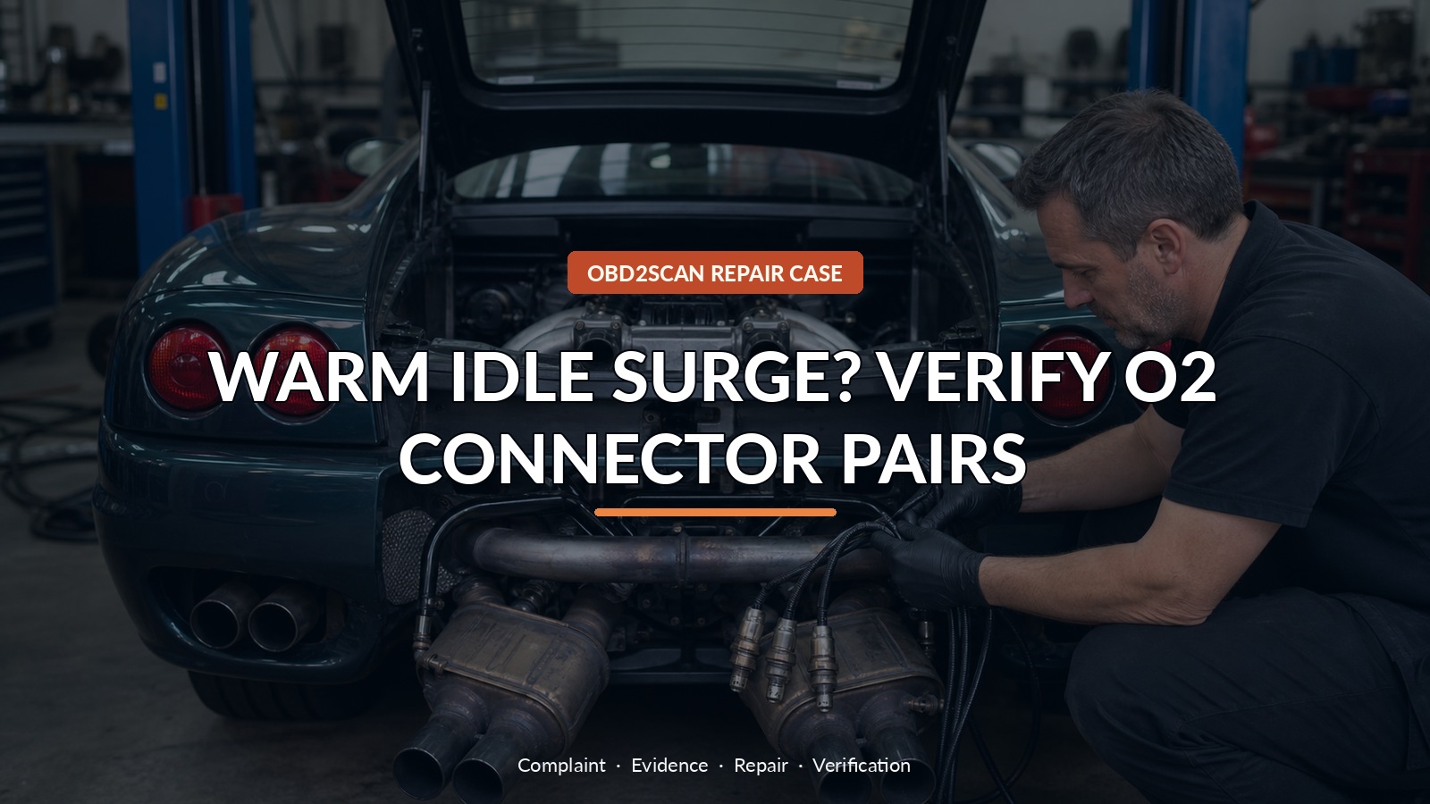
Warm Idle Surge? Verify O2 Connector Pairs
The 1999 Ferrari F355 surged badly only after warming into closed-loop operation. Both upstream oxygen-sensor codes returned even after the front sensors had been replaced; a mass-airflow sensor and coolant-temperature sensor had also made no difference. With four similar zirconia sensors, two catalysts and nearly identical connectors arranged close together, the expensive-looking problem came down to a simple routing mistake: the front and rear O2 connectors had been crossed on both banks.
A compact scope/meter such as the AUTOOL DM303 can help compare accessible oxygen-sensor voltages and slower switching behavior once the Ferrari diagram and connector identity are established. DM303 can support accessible oxygen-sensor voltage and slower waveform comparisons with wiring information; it cannot label identical Ferrari connectors by appearance, replace four-channel correlation or prove catalyst health from a brief idle trace.
This article is not a Ferrari connector map. Its method is to follow causality: watch all four signals, identify which pair changes with the surge, and verify physical routing before replacing a sensor whose code may only describe the ECM’s confusion.
Quick answer: The engine followed the signals labeled downstream because identical front and rear O2 plugs were crossed. Correct routing restored normal trim and warm idle.
In this guide
- Warm closed loop defined the test window
- Two bank codes make a common cause more plausible
- Watch all four sensors before replacing a fifth part
- Match the surge to the signal that leads it
- Disconnect one logical pair at a time
- Identical plugs turn routing into a diagnostic check
- Reconnect by function and let fuel trim relearn
- Verify idle, switching and catalyst separation together
Warm closed loop defined the test window
The temperature boundary was the first useful clue. The engine behaved better cold and began hunting as closed loop took control. That focused attention on feedback used after warm-up without proving the O2 sensors themselves were bad. Two simultaneous front-sensor codes on separate banks made a common cause more plausible than two identical new sensors failing together. Fuel pressure, intake integrity and basic airflow still deserved checks, but the four O2 signals could show how both banks were being controlled.
Two bank codes make a common cause more plausible
At hot idle, the upstream signals did not switch at the expected rhythm. Both banks followed the same slow rich-to-lean trend, while fuel trim chased the oscillation. The downstream sensors showed good delayed catalyst behavior on first inspection. Nothing appeared open circuit, and airflow and throttle relationships looked reasonable. Watching longer supplied the clue: engine speed changes aligned more closely with the pair labeled downstream than with the pair labeled upstream.
Watch all four sensors before replacing a fifth part
Correlation does not require guessing which wire color the harness builder intended. When the engine surged, note which waveform moved first and which followed. Here the apparent post-catalyst pair seemed to influence fuel control. Disconnecting the supposed upstream sensors did not stop the surge. Disconnecting the supposed downstream pair did. That reversible test showed the ECM was using the physical rear connectors as its front feedback, or the labels and physical placement no longer matched.
Match the surge to the signal that leads it
Some strategies can substitute a downstream sensor after an upstream failure, so that possibility was considered. The immediate warm closed-loop behavior and absence of a good reason to reject both new upstream signals made substitution less convincing. More importantly, all four sensors shared the same connector style and terminal arrangement, and the front and rear plugs on each bank sat close together with similar lead lengths. The harness could be assembled incorrectly without force or an obvious mismatch.
Disconnect one logical pair at a time
Each connector was traced to the physical sensor rather than identified by where it happened to lie. Both banks had front and rear connections crossed. The usual colored identifiers were absent. This kind of fault often follows exhaust or sensor work, but the exact moment of creation could not be established. The useful finding was physical: the ECU pins intended for pre-catalyst control were connected to post-catalyst sensors.
| Observation | What it changed |
|---|---|
| Both banks show similar slow control | Search for one shared setup problem |
| Unplugging labeled front pair changes little | Those plugs may not lead to front sensors |
| Unplugging labeled rear pair stops surge | ECM fuel feedback is arriving through that physical pair |
| All connectors identical and nearby | Cross-connection is physically possible |
| Correct pairing restores trim and switching | Routing mistake confirmed |
Identical plugs turn routing into a diagnostic check
Fault memory was cleared and the plugs were restored to their correct functional pairs. Adaptation was monitored rather than assumed to reset with the codes. As the engine warmed, the true upstream sensors began regular switching, fuel trim settled into single digits and idle stopped surging. The downstream signals lagged and smoothed in a way consistent with oxygen storage in the catalysts.
Reconnect by function and let fuel trim relearn
Verification included both banks because the original problem affected both. The engine was allowed to pass through the same warm-up transition, not started already hot. Upstream activity, downstream delay, fuel trim and idle speed were reviewed together. A single clean minute would not prove catalyst efficiency or long-term sensor health, but it did show that correct connector pairing restored the control relationship that had been inverted.
Verify idle, switching and catalyst separation together
On another F355, warm surge could still come from intake leakage, fuel pressure, airflow measurement, temperature input, ignition, injectors or a genuine O2 fault. Do not swap connectors experimentally. Trace them using the wiring diagram and physical sensor locations, mark them before disconnection and change one pair only when the evidence says labels and behavior disagree.
The case was solved by asking which signal controlled the symptom, not which connector somebody had called ‘front.’ That distinction saved another round of high-cost parts. Before any multi-sensor exhaust job, label both ends and photograph the routing. Afterward, let warm-up behavior confirm that upstream sensors control mixture and downstream sensors report what the catalysts did with it.





Comments 0
Questions, fixes, and real-world diagnostic notes from readers.
Be the first to share a diagnostic result or ask a follow-up question.