
2016 Range Rover TDV6 P2453 or P2455? Test the DPF Pressure Signal Chain

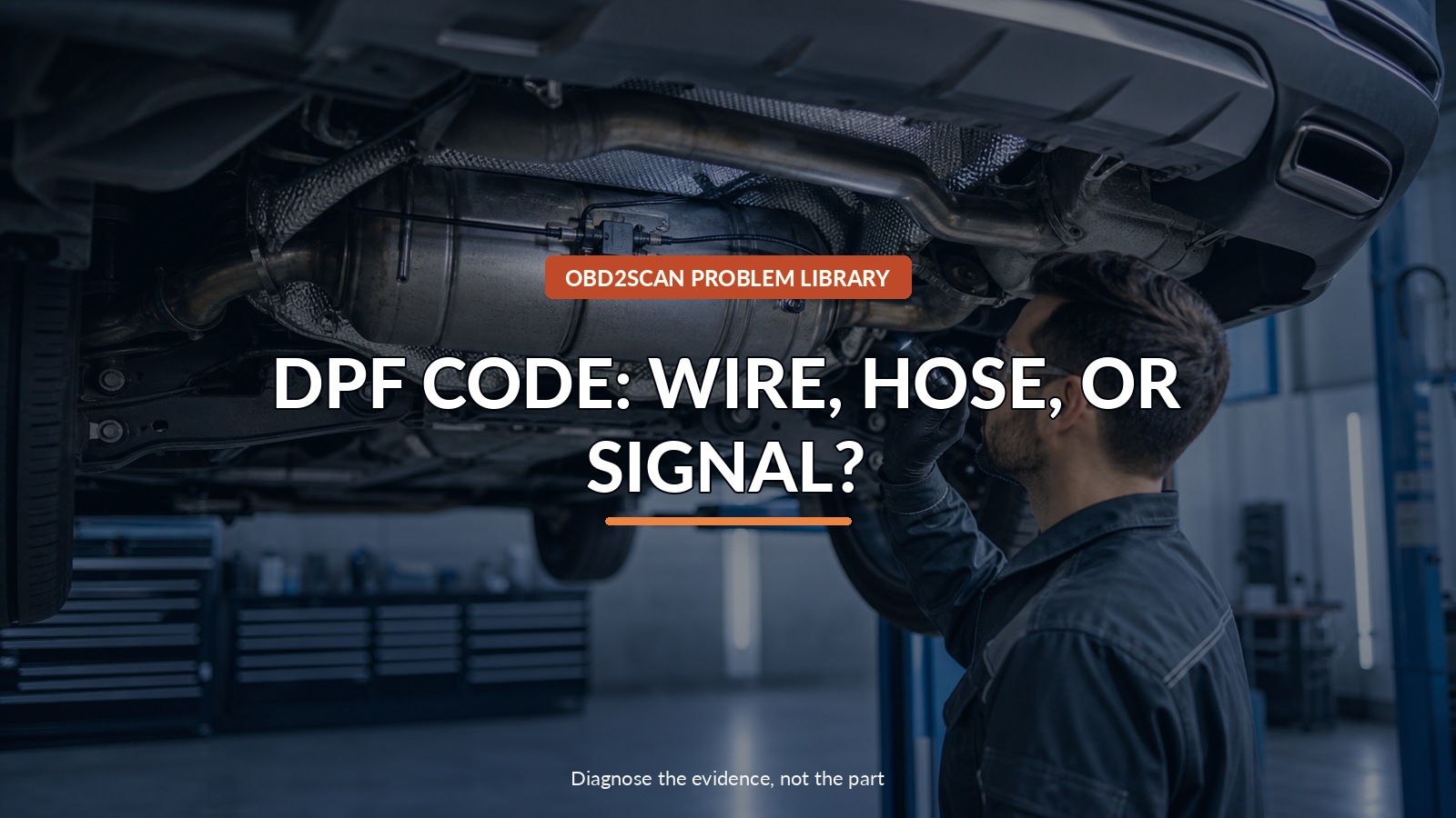
Dpf Code: Wire, Hose, Or Signal?
P2453 or P2455 contains “diesel particulate filter pressure sensor” in its description, but it does not say “replace the DPF.” On the covered 2016 Range Rover diesels, Jaguar Land Rover’s own sequence begins with the differential-pressure sensor wiring. Keep three witnesses separate: the electrical circuit, the two pressure hoses, and the pressure difference across the filter.
A low-range differential-pressure gauge can provide an independent pneumatic comparison when connected to cool, correctly identified hoses within its rating. The AUTOOL PT503 mini differential pressure gauge is one option for that narrow task. It cannot validate sensor electronics, find an intermittent harness fault, command regeneration, judge ash loading from one reading, or prove the DPF needs replacement.
The diagnostic order matters because an open wire, short, split hose, plugged pressure takeoff, biased sensor, and truly restricted filter can produce very different repairs while sharing similar dashboard language.
Quick answer: Preserve the exact DTC subtype, inspect differential-pressure sensor wiring first, then prove hose integrity, zero, and pressure response before judging the filter.
In this guide
- Do not translate the code into a blocked filter
- Confirm the TDV6 VIN and hardware gate
- Preserve code status before clearing
- Let the wiring testify first
- Inspect hoses and establish a zero
- Compare differential pressure only under specified conditions
- Keep regeneration and parts decisions downstream
- Verify the circuit through the original state
Do not translate the code into a blocked filter
Save all PCM and related module codes with subtype, status, mileage, and freeze frame. JLR’s bulletin names P244A-95, P2453-28, and P2455-22; the suffixes matter because they describe failure modes more precisely than the five-character base code. Record regeneration history, soot/ash estimates where supported, exhaust temperatures, differential-pressure sensor data, engine load, and recent short-trip use.
Do not initiate a forced regeneration from a generic instruction. Stop work if exhaust components are hot, wiring is melted, or fuel/oil conditions are unsafe. Exhaust temperature can ignite nearby material, burn people, damage an already-faulted system, or worsen an engine issue. Regeneration belongs in an approved area after the underlying code branch and oil/fuel conditions are checked.
Confirm the TDV6 VIN and hardware gate
LTB01192NAS1 covers listed VIN ranges of 2016 Range Rover Sport (LW) and Range Rover (LG) with the 3.0L TDV6 Gen 2 in North America. The bulletin lists different differential-pressure sensor part numbers for single-speed and twin-speed transfer-case configurations.
Confirm the full VIN, engine, transfer-case equipment, sensor and hose routing, software level, previous DPF repairs, and latest JLR procedure. A 2016 badge alone does not select a part. A technical bulletin is also separate from recall or emissions-warranty eligibility.
Preserve code status before clearing
An intermittent open may disappear when a harness is moved, and a high/low signal code may not reset at idle. Photograph the original scan and record key-on/engine-off pressure signal before clearing. Compare barometric and exhaust data only according to current service definitions.
Build a simple incident card:
| Witness | As-found record | Decision it can change |
|---|---|---|
| Electrical | DTC subtype, supply, ground, signal, wiggle response | Wiring repair versus pneumatic checks |
| Pneumatic | Hose routing, cracks, blockage, condensation, zero | Hose/takeoff repair versus sensor comparison |
| Filter | Differential pressure at specified speed/load | Restriction investigation after circuit integrity |
If one witness is missing, do not let another answer for it.
Let the wiring testify first
JLR instructs technicians to inspect the differential-pressure sensor wiring for a short or open before replacing the sensor. Use the exact wiring diagram, connector face, terminal tools, and approved harness-repair method. Inspect heat damage, chafe, tension, water intrusion, pin fit, previous probes, and routing near exhaust components.
Voltage, ground, and signal tests must be made in the specified connected or disconnected state. An ohmmeter can show continuity through a single strand that fails under load. A stable signal at idle cannot disprove a vibration- or heat-triggered interruption. If a wiring fault is found, repair it first and perform JLR’s post-repair diagnostic sequence rather than stacking a sensor onto the job.
Inspect hoses and establish a zero
Work only when exhaust components are cool. Mark the two pressure hoses before removal so they cannot be reversed. Inspect for melting, cracking, softness, kinks, condensation, soot blockage, loose fit, and plugged exhaust takeoffs. Do not blow unrestricted shop air toward the sensor or DPF.
With both sides at the same known pressure, the sensor and independent gauge should establish a plausible zero according to the service procedure. A nonzero offset can come from a biased sensor, unequal trapped pressure, blocked line, hose reversal, or the test setup. Correct the plumbing evidence before interpreting filter restriction.
Compare differential pressure only under specified conditions
Use JLR’s engine speed, temperature, and load conditions; no universal pressure number fits every DPF, altitude, flow rate, or soot state. Record pressure at the same points before and after a controlled change. Keep hoses secured away from hot or rotating parts.
A pressure increase with exhaust flow is expected. A value that is implausible key-on/engine-off, fixed across large flow changes, or inconsistent with an independent pneumatic reading points toward sensing or plumbing. High repeatable differential pressure after hose and sensor integrity is proved opens a filter-loading investigation—it still does not decide whether soot, ash, damage, or another engine fault is responsible.
Keep regeneration and parts decisions downstream
The bulletin’s workshop path can lead to sensor replacement after the wiring gate and uses approved diagnostic software afterward. Follow the current version; do not generalize old software-pack instructions or part numbers to every market. If codes persist through the specified cycles, JLR directs additional sensor-related work in its professional procedure.
Before any regeneration or DPF replacement, investigate conditions that created abnormal loading: temperature-sensor plausibility, fueling, boost and air leaks, EGR behavior, oil consumption, drive pattern, and interrupted regenerations. A new filter without the cause can become the next blocked filter.
Verify the circuit through the original state
Restore hose orientation, clamps, heat protection, wiring routing, and connectors. With the approved battery support and diagnostic platform, run the specified ignition cycles, read all codes, and compare sensor data at key-on/engine-off, idle, and the original safe load.
The result is complete when wiring remains stable under heat/vibration conditions, the pneumatic zero and flow response are plausible, relevant codes do not return, and any regeneration history behaves normally. A cleared P2453 after replacing a filter is not evidence that the filter was the cause.



Comments 0
Questions, fixes, and real-world diagnostic notes from readers.
Be the first to share a diagnostic result or ask a follow-up question.