
Audi Q5 U060B00? The Broken Wire May Be Hidden Under the Tape

U060B00: Look Under The Tape
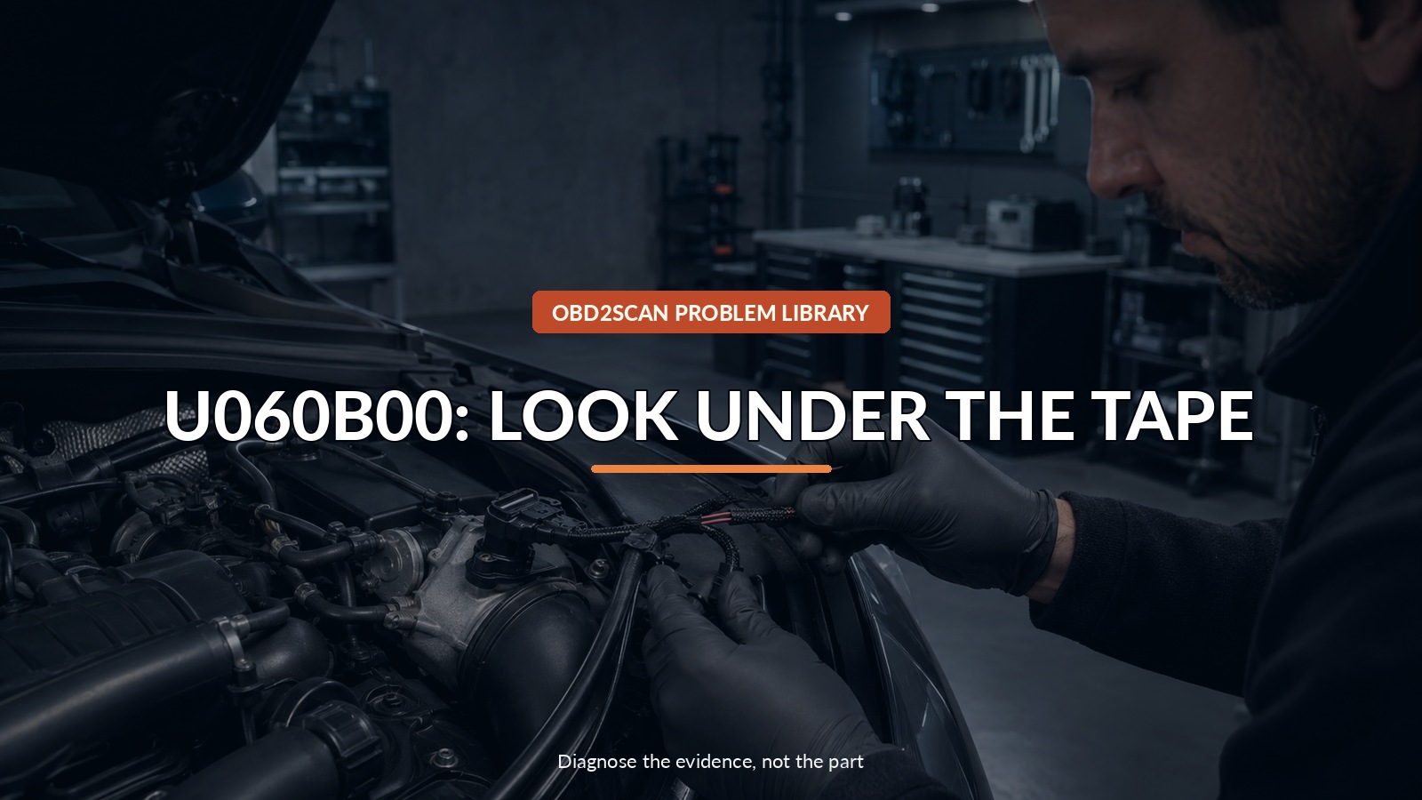
An Audi Q5 with U060B00 does not automatically need a boost-pressure sensor. In Audi TSB 2074392/2, vibration can break a wire close to the G31 charge-pressure-sensor connector, and the damage may remain hidden until the connector is professionally de-pinned or the harness tape is opened. Preserve the intermittent code before anyone moves the loom.
Once Audi’s wiring diagram identifies the exact low-voltage circuit and expected state, a circuit tester can help establish voltage or continuity. An AUTOOL BT160 can support that bounded measurement on an identified 12V/24V vehicle circuit. It cannot safely de-pin T3y, expose a hidden break without inspection, interpret network communication, or replace Audi’s specified harness repair.
Intermittent evidence is fragile: touching the loom may temporarily restore the conductor. Save the fault state first, then let movement, inspection, and measurement answer the same question in that order.
Quick answer: Preserve the intermittent U060B00, then inspect the short G31/T3y harness flex point even when intact insulation hides the broken conductor.
In this guide
- Write down what the road was doing when the MIL appeared
- Preserve U060B00 before disturbing the harness
- Check the January 2025 production boundary
- Locate G31 and the T3y flex point
- Do not stop when the insulation looks intact
- Measure only from the correct Audi wiring information
- Repair length and strain relief as a system
- Verify with movement, a rescan, and an evidence photo
Write down what the road was doing when the MIL appeared
Intermittent wiring faults need a scene. Note engine speed, acceleration, road texture, temperature, rain, and whether the lamp disappeared after a restart. Did it happen while crossing a rough expansion joint, climbing under boost, or idling smoothly? Save a short dashboard video only when parked safely; never chase a warning with a phone in hand.
Those observations help separate an event influenced by vibration from a fault that is present continuously. They do not prove a broken conductor, but they give the technician a condition to reproduce. If the Q5 loses substantial power, runs roughly, or displays a stop warning, reduce load and seek assistance rather than repeatedly forcing the event.
Preserve U060B00 before disturbing the harness
Perform a complete scan and record whether U060B00 is static, intermittent, pending, or history. The bulletin locates it in engine electronics J623 and defines it as lost communication with turbocharger/supercharger boost sensor “A.” Save freeze-frame or extended environment data where available, plus any supply-voltage or network codes from other modules.
Do this before wiggling, disconnecting, or unwrapping the harness. Simply touching a weak conductor may restore contact and erase the most useful symptom. Clearing codes at the start also removes the link between the failure and the driving condition that set it. A clean scan after manipulation is not proof that the repair is complete.
Check the January 2025 production boundary
Audi lists 2022–2025 Q5 vehicles and says an optimized production process began on January 16, 2025. Build date is context, not a substitute for VIN and current dealer information. A vehicle produced after that date can still have a damaged wire for another reason; an earlier vehicle with U060B00 still needs evidence at the specified connector.
| Finding | What it supports |
|---|---|
| Scoped model, pre-improvement build, vibration-linked U060B00 | Inspect Audi’s named flex point early |
| Same code with multiple low-voltage/module faults | Stabilize battery and network basics before narrowing |
| Harness intact at T3y | Continue current guided fault finding |
| Physical break found near G31 | Perform the specified connector/harness repair |
The bulletin is service information, not a recall declaration. Confirm warranty or campaign status for the individual VIN rather than inferring it from model year.
Locate G31 and the T3y flex point
Audi directs attention to connector T3y at charge-pressure sender G31 and the short harness section where it leaves the main bundle. The relevant failure is not necessarily at the sensor body. Look for tension, a sharp bend, evidence that the loom has been pulled during previous service, and a section that moves more than its support points.
Do not tug hard on individual wires. A conductor can be fractured inside intact insulation, and pulling may convert an intermittent fault into a complete open or move the break away from its original location. Use the current component location and wiring diagram; modern engine bays contain several visually similar three-wire sensors.
Do not stop when the insulation looks intact
Audi warns that the damage may become visible only after de-pinning the connector or removing harness tape. That work requires correct terminal-release tools, cavity identification, and a plan to preserve the original pin order. Before opening anything, photograph the connector, wire colors, harness exit, clips, and tape overlap.
A technician can gently flex the identified section while monitoring the relevant signal, supply, ground, or continuity under the correct conditions. The purpose is to correlate movement with a repeatable electrical change. Avoid piercing insulation unnecessarily; poorly sealed probe holes create future corrosion. If no change occurs, do not manufacture one by bending the loom beyond its installed range.
Measure only from the correct Audi wiring information
A code saying “lost communication” does not tell you which cavity should have power, ground, signal, or network activity. Use the exact wiring diagram for the VIN. Check meter reference points and load state; an unloaded continuity beep can pass through a nearly broken conductor that fails when current flows.
Likewise, a powered probe is not permission to inject voltage. Never apply power to an unknown sensor or module circuit. Start with passive voltage, ground-quality, and continuity/voltage-drop tests specified by Audi. Compare the suspect wire with the other conductors in the same connector only when the diagram confirms they serve comparable functions.
Repair length and strain relief as a system
Audi’s repair does more than join a severed copper strand. It specifies a replacement connector housing, repair wires, crimps, protective cap, finished branch length, exit position, tape, and harness support. Those details control strain: an electrically perfect splice placed at the same flex point may fail again.
This is why a twisted-and-taped roadside joint is not an equivalent repair. The connector must seal, terminals must lock, crimps must be made with the correct tooling, and the repaired branch must move without pulling at G31. Preserve unedited, in-focus evidence of the original damage for the repair record while protecting the owner’s face, plate, and personal data.
Verify with movement, a rescan, and an evidence photo
After reassembly, clear the documented faults and repeat the original operating condition as safely as possible. Monitor the boost-sensor signal and code status while applying only normal harness movement. The MIL should remain off, the signal should stay plausible, and no supply, ground, or network codes should appear in other modules.
The handoff should show the original U060B00 state, the exact broken-wire location, the completed strain-relieved repair, and the postrepair scan. If the code returns with the T3y repair intact, reopen guided diagnosis rather than replacing G31 or J623 from the fault text alone. The value of this repair is not that the lamp went dark once; it is that the vibration-linked failure can no longer be reproduced.



Comments 0
Questions, fixes, and real-world diagnostic notes from readers.
Be the first to share a diagnostic result or ask a follow-up question.