
How to Walnut-Blast Intake Valves with the AUTOOL HTS558

Intake-valve walnut blasting is safe only when the abrasive stays inside one controlled cleaning loop: compressed air carries media to a confirmed-closed intake valve while recovery pulls spent shell and loosened carbon back out of the same sealed port. The AUTOOL HTS558 walnut blasting machine supplies those blast and recovery paths; the technician must control the engine opening, valve position and inspection endpoint.
Quick answer: Remove the intake components by the vehicle procedure, protect every opening, rotate the engine manually until the exact target intake valve is visibly fully closed, load fresh dry compatible walnut media, and seal the correct HTS558 adapter. Start recovery before abrasive flow, clean in short passes, stop to inspect, and remove every visible particle before rotating the engine or moving to another port.
In this guide
The one-port-at-a-time safety boundary
This procedure covers accessible intake ports and intake valves where the vehicle maker permits walnut blasting. It does not authorize combustion-chamber blasting, open-valve cleaning, improvised spark-plug-hole work or abrasive contact with a coating or component not approved for the method.
Each port is a separate job. Prove its valve closed, protect its neighbors, clean and recover, pass a visual residual check, then cover the finished port before the crankshaft moves. That discipline prevents a clean-looking engine from hiding abrasive inside a cylinder.
| Control point | HTS558 setup | Pass condition |
|---|---|---|
| Media | Fresh dry compatible walnut shell; current product specification describes 0.6–1.2 mm and about 2–4 kg | No moisture, clumps, unknown debris or blocked filter clearance |
| Recovery | Built-in 1200 W recovery motor and filter path | Stable suction through sealed adapter before blasting |
| Blast energy | Compatible external dry-air supply | Stable delivery within delivered-machine and lowest component limits |
| Target | One accessible intake port with intake valve fully closed | Closure confirmed by vehicle procedure and direct evidence |
| Endpoint | Short pass followed by inspection | Approved deposit condition, no damage and no residual loose media |
For a broader machine walkthrough, filter care and full shutdown details, see the complete AUTOOL HTS558 setup and maintenance guide; the sequence below concentrates on a repeatable intake-port cleaning cycle.
Before you start
- Confirm carbon deposits are relevant to the complaint and record codes, live data and comparable before images.
- Obtain the engine-specific intake-removal, manual crank-rotation, valve-position and reassembly procedure.
- Prepare new seals, port plugs, borescope or strong light, controlled vacuum equipment and a complete tool/fastener inventory.
- Wear eye, hearing, hand and respiratory protection selected for the walnut-media SDS and shop assessment.
- Inspect the HTS558 cord, ground, latches, filter, bucket, recovery hose, gun, nozzle, adapters, seals and casters.
- Use a dry compatible compressor supply and grounded outlet matching the delivered machine nameplate.
If you cannot directly prove the target intake valve fully seated and protect every neighboring opening, do not connect compressed air or introduce walnut media.
HTS558 intake-valve walnut-blasting procedure
Step 1: Confirm that cleaning is the right repair path
Diagnose before disassembly. Record the symptom, fault codes, misfire counts, fuel trims and mechanical test results that matter for the engine. Carbon can contribute to airflow and combustion complaints, but ignition, injection, timing, compression, air leaks and oil entry can produce similar symptoms.
Create a baseline image of each accessible valve under consistent lighting. Define the post-cleaning tests now so the job is judged by vehicle behavior as well as appearance.
Step 2: Expose the intake ports and control every opening
Cool and isolate the vehicle as the service procedure requires, then remove the intake manifold and related components in the specified order. Label connectors, lines and fasteners, and prevent debris from entering exposed fuel, coolant, vacuum or electrical connections.
Plug or cover every intake runner except the port being inspected. Count protection pieces in and out. Stop if liquid, foreign material, damaged surfaces or an unapproved coating is visible.
Step 3: Build the HTS558 blast-and-recovery loop
With power and air disconnected, attach the recovery hose and elbow, then fit the chosen blasting tube to the gun through the elbow’s intended opening. Select the adapter by actual port geometry; it must cover the port without damaging an edge or forcing nearby components.
Trace the path by hand: compressor to gun and nozzle, then target port to elbow, recovery hose, filter and bucket. Support both hoses so their weight cannot pull the adapter seal open.
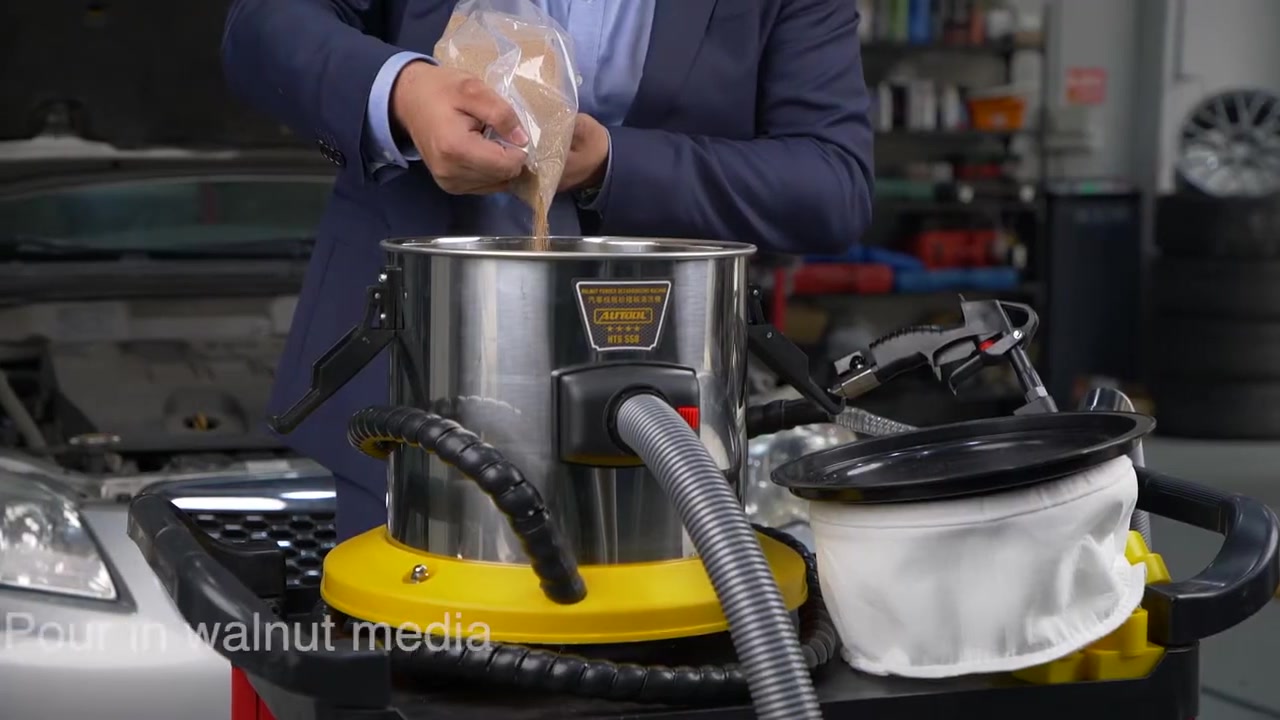
Step 4: Load clean, dry walnut media
Open the machine only while isolated. Lift the head as directed, remove and protect the filter’s clean side, and inspect the bucket for water, oil, metal, glass, carbon clumps or old unknown abrasive.
Load fresh media compatible with the delivered HTS558. The current product record describes 0.6–1.2 mm walnut shell and about 2–4 kg, but keep the filter and airflow path clear and confirm the delivered revision. Refit the filter and latch the head evenly.
Step 5: Prove the exact intake valve fully closed
Rotate the engine manually using the approved tool, direction and reference points. Use direct sight and a borescope where needed to confirm the target intake valve is fully seated. Piston height alone does not prove valve position, and the starter motor is not a controlled positioning tool.
Recheck every neighboring cover after rotation. If the target cannot be seen or valve closure remains uncertain, stop before air or media is introduced.
Step 6: Seal the adapter and test recovery first
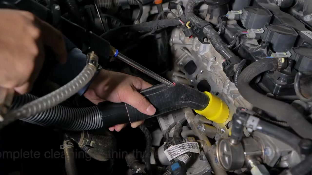
Seat the correct adapter squarely on the selected port and support the hose. Connect grounded power, leave the gun released and switch recovery on. Listen for stable flow and inspect the adapter perimeter, elbow, hose, filter path and machine connection.
Weak suction, a collapsing hose or a seal that shifts must be corrected before blasting. More compressor pressure cannot repair a poor recovery path.
Step 7: Set dry air and verify nozzle control
Connect the dry filtered air supply with the gun released. Set the machine and compressor only within the delivered instructions and the lowest-rated hose, coupler, adapter and nozzle. Confirm stable flow under actual demand rather than relying only on the compressor tank gauge.
With recovery established, use an allowed brief air-only check to prove the nozzle is clear. Keep the tip off the valve, seat, stem and runner wall. If flow pulses or stops, isolate the machine and clear the cause away from the engine opening.
Step 8: Blast in short passes with recovery running
Start abrasive flow only after the adapter remains sealed. Sweep the nozzle across approved deposit surfaces, keep it moving and release the gun before changing angle or hand support. Recovery stays on throughout the pass.
Stop after a short observable cycle and inspect. A one-to-three-minute product example is not a universal timer; deposit hardness, access, media, air delivery and engine surfaces differ. Continue only while deposit removal is controlled and the underlying surface remains protected.
Step 9: Recover and inspect before moving the crank
Release abrasive but keep recovery active while sweeping the port and adapter area. Then use approved vacuum, controlled air where permitted, bright light and a borescope to inspect the valve pocket, runner, sealing edges, recesses and neighboring openings.
Remove every visible walnut particle and carbon fragment. Do not depend on walnut shell being combustible. If an area cannot be inspected, restore access or use an approved recovery method before rotating the engine.
Step 10: Protect the completed port and repeat
Photograph the result from the baseline angle and cover the completed port. Move to the next runner only after that port passes surface and contamination checks. Rotate the crank by the approved method and independently prove the next valve closed.
Recheck adapter seal, nozzle clearance, recovery airflow, filter state and media dryness at every move. Never assume one setup remains valid across differently shaped runners.
Step 11: Shut down, reassemble and verify the vehicle
Release the gun, keep recovery on for final collection, then switch recovery off. Close and depressurize the air supply, disconnect air, switch off power and unplug before opening or cleaning the machine.
Make a final counted inspection of all ports and protection pieces. Install required new seals, use specified fastener sequence and torque, reconnect every line and sensor, then run leak checks, a diagnostic scan, required adaptations and the approved functional test against the original baseline.
Three gates for a finished port
A brighter valve face is useful evidence, but release the engine only when all three gates pass.
| Gate | Pass | Failure response |
|---|---|---|
| Surface | Required deposit removed without visible contact damage | Stop blasting and assess the surface |
| Contamination | No loose walnut or carbon in target or neighboring openings | Continue controlled recovery and inspection |
| Vehicle | Correct reassembly, no leak/new code, required function restored | Reopen diagnosis rather than promising a cleaning cure |
Never blast when the target intake valve position is uncertain or recovery is not sealed and stable. Lost abrasive can enter the cylinder or another engine opening, and the absence of immediate noise does not prove the engine is safe to start.
Common mistakes
- Inferring valve closure from piston position or a nearby valve.
- Holding the blast gun beside rather than through the recovery elbow.
- Loading damp, reused or unknown media.
- Increasing pressure to overcome a blocked filter or weak seal.
- Using elapsed time instead of inspected surface condition as the endpoint.
- Rotating or restarting the engine before all visible media is removed.
Frequently asked questions
Does AUTOOL HTS558 include an air compressor?
No. Its electric motor powers recovery; walnut blasting requires a compatible external dry compressed-air supply.
How long should I blast each intake valve?
Use short passes and inspect. A product example is not a universal endpoint; stop at the approved surface condition with no damage or residual media.
Can I blast with the intake valve open?
No. For this intake-port procedure, the exact target valve must be visibly and procedurally confirmed fully closed before abrasive flow.
Can recovered walnut shell be reused?
Do not assume it can. It may contain oil, moisture, metal or carbon contamination; fresh dry media is the controlled starting point.
Does a clean before-and-after image prove the repair?
It proves visible deposit change only. Reassembly, leak checks, scan data and the original symptom determine the vehicle result.
One-port cleaning record
- Target valve identity and full closure confirmed.
- Neighboring ports and connections protected and counted.
- Correct adapter sealed and recovery stable before blast.
- Fresh dry media and stable air delivery verified.
- Short-pass surface result photographed.
- No visible loose media or carbon remains.
- Completed port covered before crank rotation.
- Reassembly and vehicle validation recorded.
The best HTS558 result comes from repeating the same disciplined cycle at every port: prove closed, seal, recover, blast briefly, inspect completely and protect the result. Control of the engine opening matters more than speed.







Comments 0
Questions, fixes, and real-world diagnostic notes from readers.
Be the first to share a diagnostic result or ask a follow-up question.