
How to Use the FXTUL F8-B Motorcycle Dash Cam and HUD

The FXTUL F8-B is a motorcycle dash camera, HUD and tire-pressure display. This guide combines the exact F8-B touchscreen, dual-camera, TPMS and parking-function record with a motorcycle-safe mounting, wiring, setup and verification workflow.
Quick answer: Inventory the exact F8-B kit, plan the display, front/rear cameras and harness route, then isolate the motorcycle battery. Mount without blocking controls or sightlines, route every cable clear of heat, steering and suspension and have each labeled power lead connected by the delivered diagram—not by color guesswork. Fit and leak-check the front/rear TPMS sensors, complete stationary settings and camera playback checks, then prove full movement clearance and perform only a controlled legal ride check.
In this guide
Before you start
An accessory display can create electrical faults, battery drain, steering restriction, tire-valve leakage or rider distraction when it is mounted or wired incorrectly. Stabilize the motorcycle, keep its exact wiring and trim procedure open and use qualified electrical installation when a feed or protection requirement is uncertain. The F8-B must support the ride without becoming another hazard or obscuring an original warning.
- confirm the exact F8-B 5-inch main unit and inventory both cameras, extension leads, power harness, brackets, remote, TPMS sensors, hardware, memory card and delivered manual;
- verify the motorcycle electrical system is within the published 5-40V input range and identify exact protected connection points from its wiring information;
- plan display and camera mounts that preserve sightline, instruments, steering, suspension, controls and service access;
- inspect valve stems and establish the correct front and rear cold pressures with an accurate gauge;
- check local recording, privacy, screen-use and mounting rules; and
- prepare suitable support, trim tools, loom protection, torque information and leak-check materials before disassembly.
Keep the manual supplied with the F8-B beside the motorcycle’s exact wiring, trim, tire-pressure and accessory-installation information. The delivered harness labels and vehicle procedure control if another display, video or remembered wire color differs.
F8-B controls and specifications
The current product record highlights Five-inch touchscreen, Front and rear recording, Tire-pressure monitoring, Ride-data display, Parking-event functions. Confirm each relevant control on the physical unit before use; related motorcycle displays can look similar while using different brackets, connectors, harness leads, cameras and menus.
| Specification or function | Current model |
|---|---|
| Working Current | 600mA |
| Operating Temperature | -20°C to +80°C |
| Display | 5.0-inch touchscreen |
| Power Supply | 5-40V DC |
| Resolution | 854×480 |
| Storage | 32GB memory card shown in the current product package |
The current F8-B record specifies 5-40V DC input, 600mA working current, 10mA standby current, a 5-inch 854×480 display and operation from -20°C to +80°C. Its text lists a 110-degree camera angle while several exact gallery panels list 140 degrees, and the page says waterproof without publishing an ingress rating. This guide therefore makes no exact field-of-view or submersion claim: aim both real cameras on the motorcycle and protect every component and connector from pressure washing, immersion and water traps.
How to use the F8-B
Step 1: Confirm the F8-B kit and motorcycle fitment
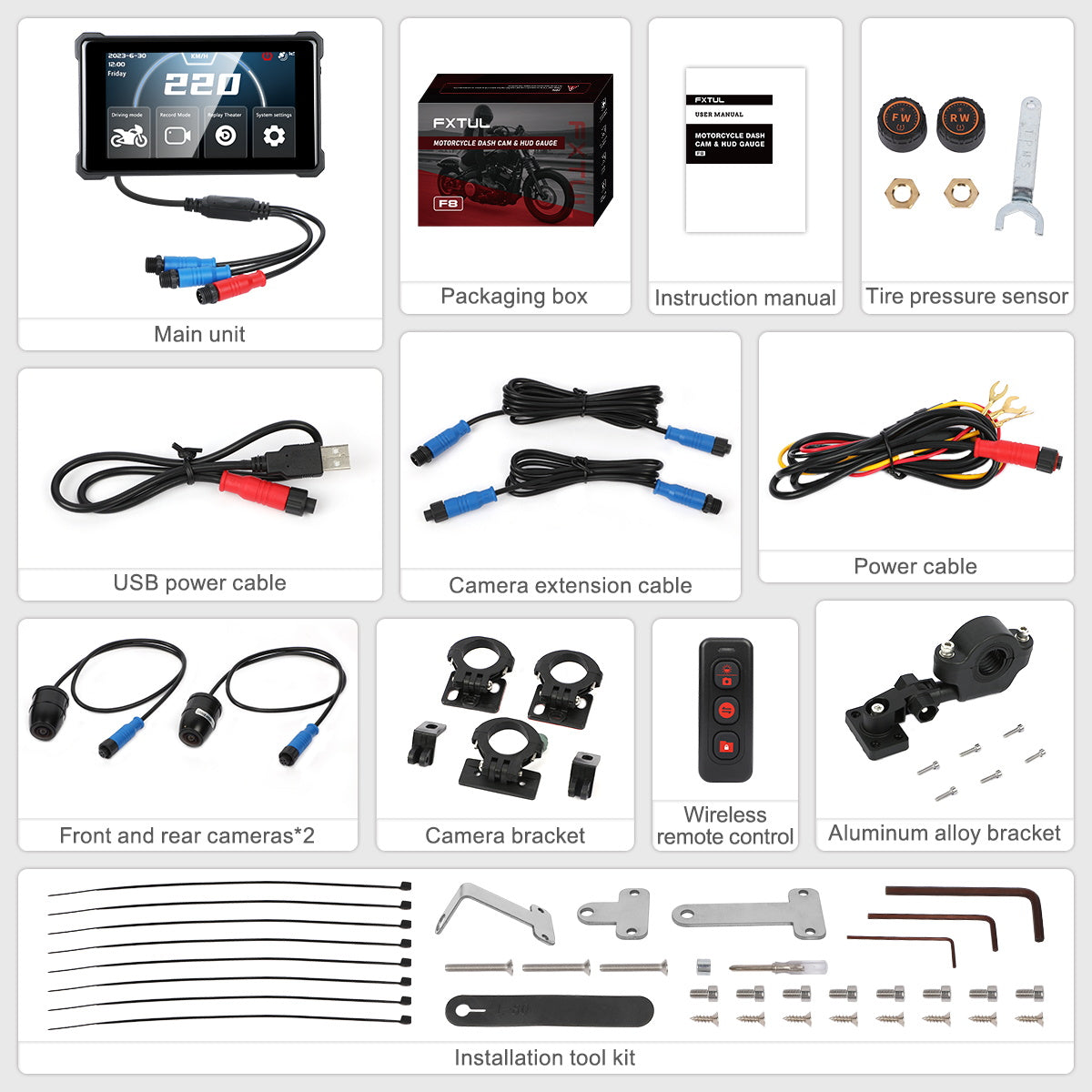
Match the main unit label and 5-inch touchscreen to F8-B, then inventory the front and rear cameras, extension leads, exact power harness, display and camera brackets, wireless remote, front/rear tire-pressure sensors, installation hardware, 32GB card and delivered manual. Confirm the motorcycle's 5-40V electrical system, handlebar or cockpit space, valve stems and service procedure are compatible before altering the vehicle.
Before moving on, confirm the main unit is the 5-inch touchscreen F8-B, every supplied part is identified, the motorcycle is compatible and the exact protected wiring points and full-clearance mounting plan are documented.
Step 2: Plan every mount, cable and legal requirement
Choose a display position visible without blocking instruments, warning lamps, steering, switches or the forward view. Plan front and rear camera views, remote access and a harness route clear of heat, sharp edges, fuel-system parts, steering, suspension and service points. Check local recording, privacy and display-use rules before installation.
Step 3: Secure the motorcycle and isolate battery power
Stabilize the motorcycle on suitable support, switch the ignition off and follow its service information before removing trim or the seat. Disconnect the battery by the motorcycle-approved sequence, normally controlling the negative connection first, and protect the loose terminal so it cannot spring back. Do not identify a circuit by wire color alone.
Step 4: Mount the touchscreen without obstructing control
Assemble the supplied aluminum-alloy display bracket in the delivered orientation, use the correct spacer and fasteners for the selected bar or structure and tighten only to the applicable bracket and vehicle limits. Sweep the steering from lock to lock and confirm the screen, bracket and harness cannot contact a control, tank, fairing, cable or brake hose.
Step 5: Mount the front and rear cameras in protected views
Identify the front and rear modules and extension leads before routing. Mount each camera on a rigid location with the intended horizon orientation, an unobstructed field of view and protection from direct exhaust heat, suspension travel, tire spray and impact. Leave adjustment available until the live image is checked.
Step 6: Route and secure the display, camera and remote wiring
Follow the existing harness path where suitable, allow service and steering loops and protect every pass-through or edge. Join only the matching keyed connectors without forcing them, keep connections away from water traps and secure the loom at intervals without crushing it. Verify full steering and suspension movement again before electrical connection.
Step 7: Connect the power harness by the delivered wiring diagram
Have a qualified motorcycle electrical installer identify the exact battery, ground and any switched or parking-function feeds required by the delivered F8-B harness. Connect every labeled lead exactly as shown in the supplied manual, preserve the specified circuit protection and terminal hardware and insulate the finished joints. Never guess lead purpose from red, yellow or black color or bypass a required fuse.
Step 8: Install and verify the front and rear TPMS sensors
Confirm the valve stems are serviceable and that the sensors marked for the front and rear wheel match their intended positions. Set cold tire pressure with an accurate gauge to the motorcycle and tire specification, install the supplied retaining hardware and external sensors by the delivered method and check for leakage. The F8-B display is a monitor, not a substitute for a calibrated gauge or valve inspection.
Step 9: Restore power and complete stationary setup
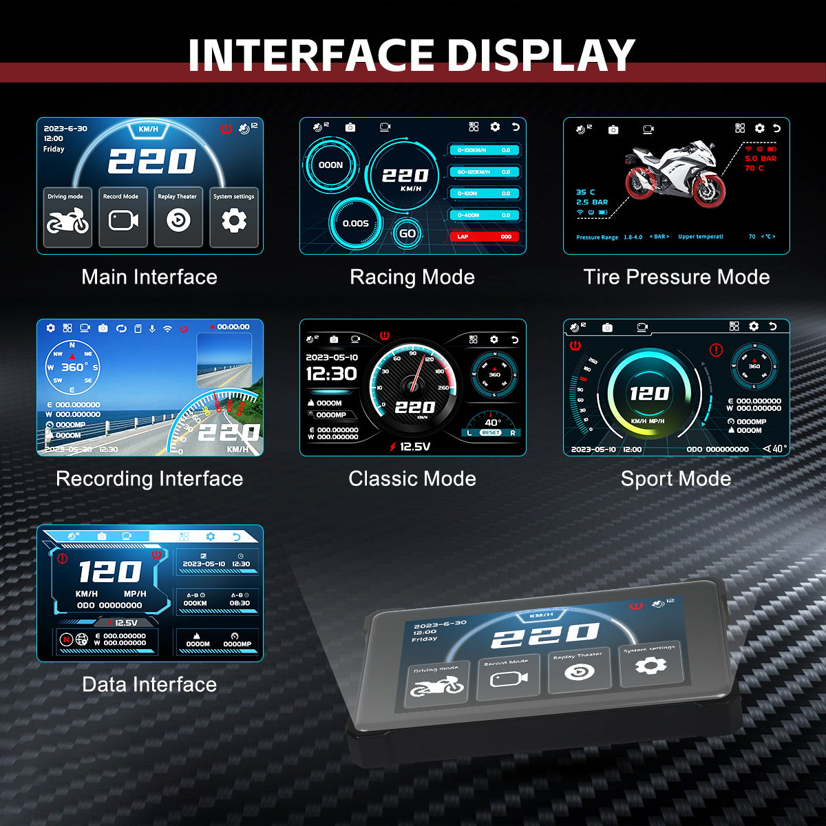
Reconnect the battery by the motorcycle procedure, refit enough structure to make the area safe and power the F8-B with the motorcycle stationary. Confirm normal startup, stable voltage and no heat, odor, blown protection or warning. Set language, date and time, units, display layout, recording options, memory card and TPMS warnings only from the delivered menu and the motorcycle's actual specifications.
Step 10: Aim both cameras and verify recording and playback
Use the live or split display to level the front and rear views while the motorcycle remains stationary, then secure the camera adjustments. Make a short controlled recording and verify both channels, date/time, card status, loop or event lock behavior and playback. A visible image is not proof that both files are being saved correctly.
Step 11: Configure remote, app and parking functions carefully
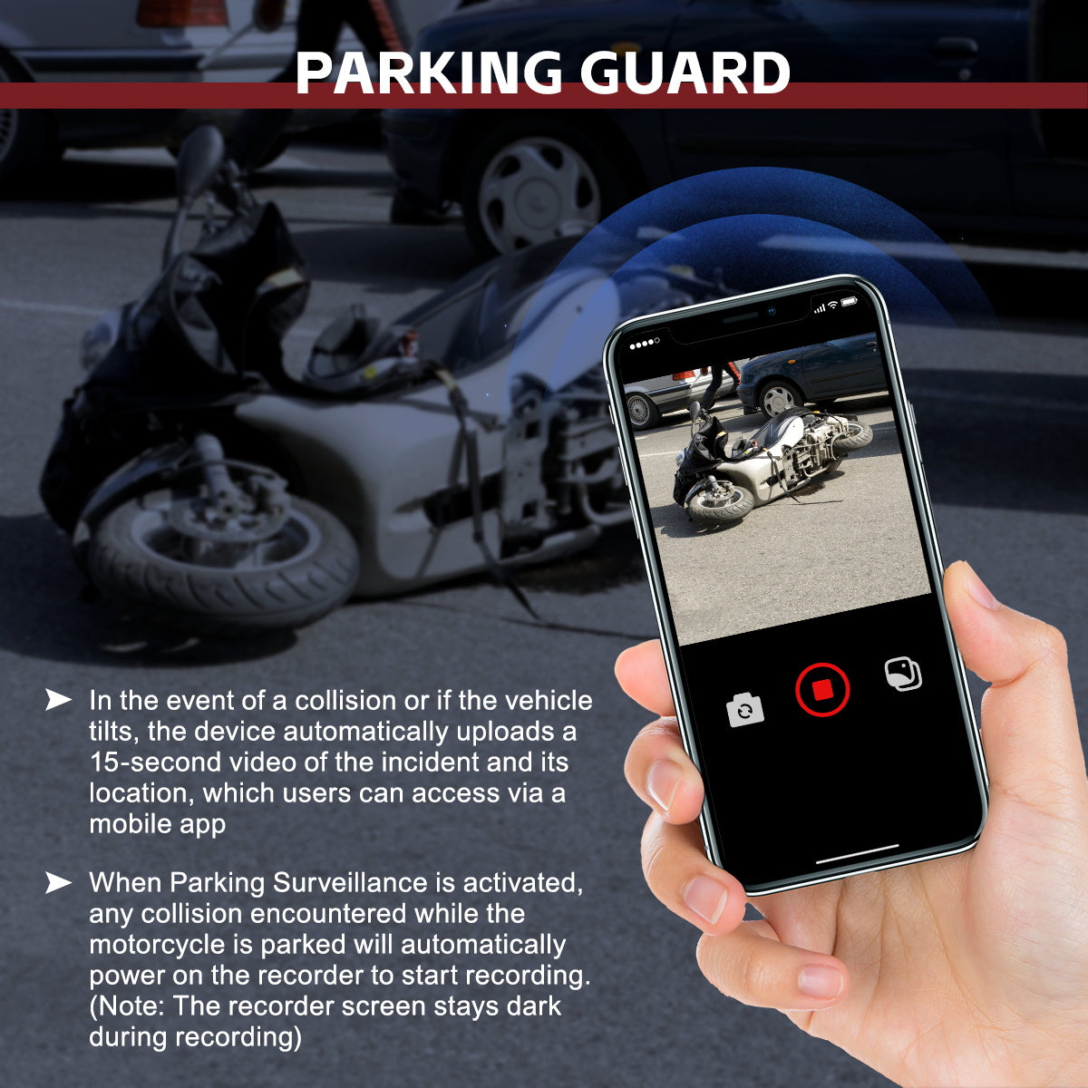
Pair or configure the wireless remote, 2.4GHz app connection and parking-event functions only through the delivered instructions. Test controls while stationary and verify where an incident clip and location can be found. Because parking surveillance may operate with a dark screen and draw standby current, confirm the chosen feed is intentional and monitor battery condition before relying on long parking periods.
Step 12: Finish the installation and perform a controlled ride check
Recheck fasteners, connector seals, loom support, tire-sensor leakage and lock-to-lock plus full-suspension clearance, then reinstall every seat, fairing and cover. Perform the first ride only in a safe legal area: confirm the display remains readable without distraction, cameras stay aimed, pressure data is plausible and no cable or bracket moves. Do not configure the unit while riding or use racing timers on public roads.
Before normal riding, confirm all trim and battery protection are restored, lock-to-lock and suspension clearance remain free, both channels save playable footage, both tire sensors are leak-free and no bracket, warning or cable is abnormal.
Read and verify the result
A successful installation is verified at three levels. Mechanically, no bracket, sensor or loom moves and full steering and suspension travel remain free. Electrically, startup is normal with stable power, no heat, odor, fault or unintended battery drain. Functionally, both cameras record and play back, pressure readings agree reasonably with a gauge, the remote and app behave as configured and the display remains useful without drawing the rider’s attention away from the road.
- Turn the handlebar fully both ways and compress or unload suspension as the service procedure permits; no cable, brake hose, throttle line, screen or bracket may tighten or touch.
- Record and play a short front/rear clip, then confirm date, time, card status and event or loop behavior rather than judging from live view alone.
- Compare each cold TPMS value with an accurate gauge and recheck both external sensors for leakage after installation and the first ride.
- Verify parking-event behavior and standby draw over an appropriate period before leaving a small motorcycle battery connected for extended storage.
- Repeat the original-instrument and warning-lamp check; an accessory display must not hide or replace required vehicle indications.
Stop and isolate power for a hot wire or connector, repeated fuse operation, unstable display, burning odor, battery discharge, camera or bracket movement, tire-valve leakage, implausible pressure, restricted steering or controls, cable contact with heat or motion, or any original warning. Do not keep riding to see whether a mechanical, electrical or tire fault clears itself.
Common mistakes and care
- Vehicle wiring must be identified from exact service information; do not assign a F8-B harness lead by color alone.
- Mount the display and route wiring so steering, braking, throttle, suspension, instruments and the rider's view remain unobstructed through their full travel.
- Use the motorcycle and tire maker's cold-pressure values and verify them with an accurate gauge; TPMS is a warning aid, not the pressure-setting authority.
- Do not adjust the display, app, cameras or racing modes while riding, and never perform acceleration timing on a public road.
- Parking surveillance can operate with a dark display and consume standby power; verify the intended feed and monitor motorcycle battery condition.
- The current product sources conflict on camera angle and provide no numeric ingress rating; do not infer a precise field of view or permission to pressure-wash or submerge components.
- Do not copy an installation sequence from a different motorcycle HUD; a smaller button-operated unit can use different brackets, connectors and wiring from the 5-inch touchscreen F8-B.
- Do not assign the power-harness leads from color alone or add an unfused connection because the screen powers up on a bench supply.
- Do not tighten a display or camera bracket until steering, suspension, fairing and service-clearance checks are complete.
- Do not set TPMS limits from a generic screen example; use the exact motorcycle and tire cold-pressure requirements.
- Do not treat a dark parking screen as proof that the unit is off, and do not pressure-wash a component without a confirmed numeric ingress rating.
- Do not operate menus, replay footage or run acceleration timers while riding or on public roads.
Frequently asked questions
Can I connect the F8-B power wires by color?
No. Identify each labeled F8-B lead from the delivered wiring diagram and each motorcycle connection from exact service information. Wire colors can vary by product revision and vehicle; preserve the specified circuit protection and use qualified installation when a feed is uncertain.
Does the F8-B tire-pressure display replace a tire gauge?
No. Set both cold pressures from the motorcycle and tire specification with an accurate gauge, then compare the F8-B readings. Investigate a mismatch or leak rather than changing pressure to make the screen look expected.
Why can the F8-B draw power while its screen is dark?
Parking surveillance is described as recording after an event while the display remains dark, and the current specification lists standby current. Confirm the intended parking feed, test the function and monitor battery condition before extended parking or storage.
Final F8-B checklist
- Exact F8-B main unit, cameras, harness, brackets, remote, TPMS sensors and supplied instructions confirmed
- Display and camera positions preserve sightline, instruments, controls and service access
- Battery isolated for installation and every labeled lead connected by the exact protected wiring procedure
- Harness secured clear of heat, edges, steering and suspension through full travel
- Front and rear TPMS sensors correctly assigned, cold pressure verified and valve leakage absent
- Both camera channels record and play back with correct time and stable mounting
- Remote, app and parking behavior verified while stationary; standby impact understood
- All trim restored and a controlled legal ride check completed without distraction, movement or warnings
The F8-B is complete only when installation quality and rider attention are both protected: mount rigidly, wire from exact data, prove every moving clearance, verify saved footage and tire pressure, and keep configuration work off the road.



Comments 0
Questions, fixes, and real-world diagnostic notes from readers.
Be the first to share a diagnostic result or ask a follow-up question.