
How to Use the AUTOOL TWB203/TWB205 Wheel Balancer

The AUTOOL TWB203/TWB205 is a professional wheel balancer. This guide combines the exact TWB203/TWB205 configuration with first-party wheel-balancing service guidance and keeps every TWB205-only aid clearly separated.
Quick answer: Start with an inspected tire and wheel, remove old weights and contamination, then center the assembly with the correct adapter. Enter and verify the wheel dimensions, select the matching correction planes, run the guarded spin, place the indicated weights and always verify with a second spin. If the result changes after remounting or needs excessive weight, correct centering or tire-and-rim condition before adding more weight.
In this guide
Before you start
A wheel balancer spins a heavy assembly at speed. The machine must already be installed, commissioned, calibrated and guarded, and the operator must understand the delivered controls. Balancing corrects mass distribution; it does not make a damaged tire, bent rim, poor centering, runout, loose hub or worn suspension safe. Inspect those conditions before treating the display as an instruction to add weight.
- identify the data plate as TWB203 or TWB205 and confirm current commissioning, calibration and pre-use inspection status;
- confirm the complete assembly is within the listed 65kg wheel and 10-26 inch rim envelope;
- inspect tire pressure, tread, bead seating, valve, repairs, rim damage and obvious radial or lateral runout;
- remove old weights, mud, stones, adhesive residue and loose debris, then dry the correction surfaces;
- inspect the 40mm shaft, centering adapters, quick nut, guard, display, controls and weight platform; and
- keep the rotating envelope clear and plan the approved clip-on or adhesive weight planes for the actual wheel.
Use the AUTOOL manual download center to locate the current instructions when a manual is available. The delivered model label and current vehicle service information control if an older image or remembered setting differs.
TWB203/TWB205 controls and specifications
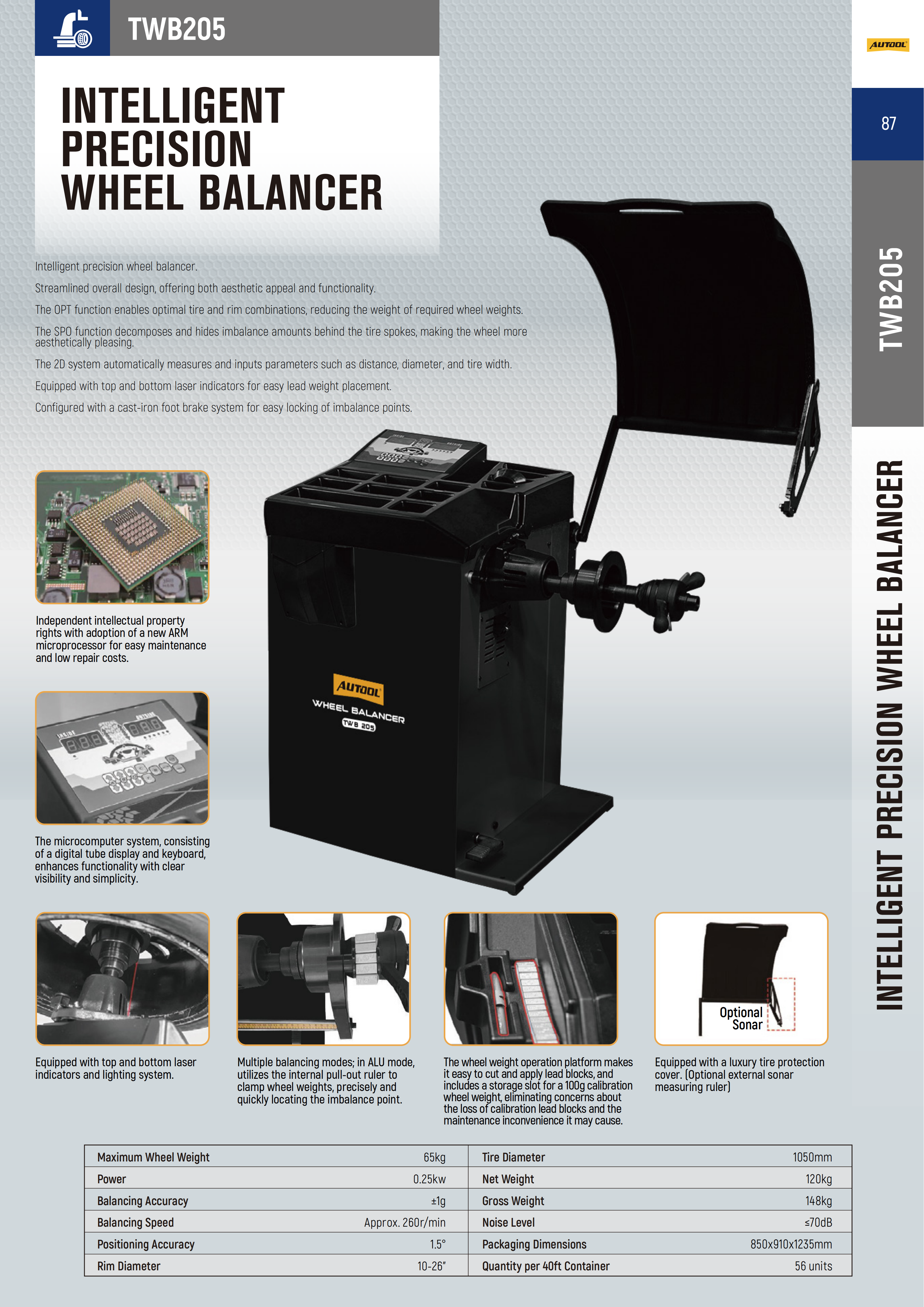
The current product record highlights TWB203 enhanced dynamic balancing, TWB205 automatic wheel-data input, TWB205 placement assistance, TWB205 OPT and SPO modes, Shared professional capacity. Confirm each relevant control on the physical unit before use; related AUTOOL models can look similar while using different ranges, air sources or operating modes.
| Specification or function | Current model |
|---|---|
| Rim Diameter | 10-26in |
| Model Positioning | TWB203: enhanced dynamic; TWB205: intelligent precision |
| Maximum Wheel Weight | 65kg |
| Power | 0.25kW |
| Balancing Accuracy | ±1g |
| Balancing Speed | Approximately 260 r/min |
| Positioning Accuracy | 1.5° |
| Maximum Tire Diameter | TWB203: 1100mm; TWB205: 1050mm |
| Noise Level | ≤70dB |
| TWB205 Assistance | 2D automatic measurement, top/bottom lasers, foot brake, OPT and SPO |
The current exact product record lists a 65kg maximum wheel weight, 10-26 inch rim range, approximately 260rpm balancing speed, ±1g balancing accuracy and 1.5-degree positioning accuracy. TWB203 accepts up to a listed 1100mm tire diameter; TWB205 lists 1050mm. These are machine specifications, not permission to service a damaged or incompatible assembly. TWB205-only 2D input, laser, foot-brake, OPT and SPO functions must never be inferred on TWB203.
How to use the TWB203/TWB205
Step 1: Confirm the variant and start with a commissioned machine
Read the machine data plate and controls to identify TWB203 or TWB205. Use this operating sequence only after qualified installation, commissioning and calibration. Confirm the wheel is within the 65kg and 10-26 inch machine envelope and open the tire, wheel and vehicle service information before work.
Before moving on, confirm the exact TWB203 or TWB205 variant, commissioning and calibration status, complete guard function, listed wheel capacity and an undamaged tire-and-rim assembly.
Step 2: Precheck the tire and wheel before balancing
Record the customer symptom and inspect tire pressure, tread, bead seating, damage, prior repairs, rim condition, valve and runout indicators. Wheel balancing can correct mass imbalance; it cannot repair a bent rim, shifted belt, damaged tire, loose hub or worn steering and suspension part.
Step 3: Remove old weights and clean the assembly
Remove the existing clip-on and adhesive weights, then clean mud, stones, loose debris and adhesive residue from the wheel. Dry the correction areas so a new adhesive weight can bond and so contamination does not become part of the measurement.
Step 4: Inspect the shaft and choose the centering adapter
Check the 40mm shaft, cone or wheel-specific adapter, pressure cup, quick nut, guard and contact surfaces for dirt, wear or damage. Select the centering method approved for that wheel design; a cone that merely fits through the center bore does not guarantee repeatable centering.
Step 5: Mount and center the wheel without visible wobble
Slide the wheel onto the shaft in the intended orientation, fit the selected adapter and secure it evenly. Rotate the assembly by hand and watch the wheel-to-adapter contact. Stop and remount if it rocks, sits against debris or shows obvious centering error.
Step 6: Enter and verify the wheel dimensions
On TWB203, enter the distance, rim diameter and width using the delivered controls and measured wheel data. On TWB205, use the 2D automatic distance, diameter and width input where fitted, then verify the displayed values rather than assuming automatic input is correct.
Step 7: Select the correct balancing mode and correction planes
Choose the mode for the actual wheel and approved weight locations: normal dynamic balancing for conventional inner and outer correction planes, or the matching alloy-wheel mode when adhesive placement is required. Use TWB205 SPO only when the exact wheel and on-screen workflow support hidden weights behind spokes.
Step 8: Lower the guard and run the measurement
Confirm no tool, hand, loose clothing or bystander is in the rotating envelope. Lower the protection cover and start the spin by the delivered control sequence. Stand clear until the machine has stopped and never try to slow the rotating tire by hand.
Step 9: Locate the indicated inner and outer correction points
Read the imbalance value for each correction plane and rotate the wheel to the indicated position only after the spin has ended. On TWB205, use the foot brake and top or bottom laser only as labeled to hold and identify the point; do not assume those controls exist on TWB203.
Step 10: Apply the specified weights to prepared surfaces
Confirm the permitted clip-on or adhesive weight type and exact correction plane for the wheel. Clean and dry the adhesive location, apply the displayed amount at the indicated point, and press adhesive weights for full contact. Do not stack weights to hide a centering or runout problem.
Step 11: Run a verification spin and correct the cause of inconsistency
Repeat the measurement with the wheel mounted exactly as before. If the residual result is outside the shop and vehicle acceptance criteria, correct the weight placement and rerun. If values move materially after a simple remount, clean and recenter the wheel and inspect the adapter, shaft, rim and tire instead of chasing the display with more weights.
Step 12: Investigate excessive correction and finish the job
When unusually high correction remains, inspect centering, radial or lateral runout, rim deformation and tire condition. Use TWB205 OPT only through its exact prompts for tire-to-rim optimization. After a verified result, remove the wheel safely, restore valve and wheel requirements, install it to the vehicle procedure and confirm whether the original vibration remains.
Before removing the wheel, confirm the verification spin is repeatable, every weight is secure, no unexplained excess correction remains and the result is recorded for the vehicle-level vibration check.
Read and verify the result
Use the verification spin—not the first displayed weight—as the completion test. A repeatable acceptable residual result shows that the assembly is balanced on the current mounting and correction planes. It does not prove the tire is round, the rim is straight or the vehicle has no hub, bearing, steering or suspension fault.
- Repeat the spin without changing the mounting; the result should remain inside the shop and vehicle acceptance criteria.
- If a weight amount or position changes materially, inspect weight adhesion, selected mode, entered dimensions and wheel movement before correcting it.
- If the result changes after removing and remounting the wheel, correct the centering method, adapter cleanliness or contact condition.
- If unusually high correction is requested, inspect tire and rim runout and damage; on TWB205, use OPT only through the exact prompted process.
- After vehicle installation, road-check the original symptom under safe conditions; a remaining vibration needs a broader vehicle diagnosis.
Stop if the guard or control does not work normally, the wheel cannot be centered without wobble, an adapter is damaged, the assembly exceeds the machine boundary, the tire or rim is unsafe, a weight or tool is loose, or the machine vibrates or sounds abnormal during spin. Isolate the machine and obtain qualified service rather than bypassing a guard, calibration or brake function.
Common mistakes and care
- Operate only a correctly installed, guarded, commissioned and calibrated machine on a level controlled workshop floor.
- Keep hands, tools, clothing and bystanders outside the rotating wheel envelope; never brake a spinning wheel by hand.
- Do not balance a damaged tire or wheel, exceed the 65kg listed wheel limit or use an adapter that cannot center the wheel repeatably.
- Use TWB205-only 2D, laser, foot-brake, OPT and SPO functions only when those controls are present and the exact task calls for them.
- A zero or acceptable balance result does not rule out runout, tire construction faults, hub issues or steering and suspension causes of vibration.
- Do not leave old weights, stones, mud or adhesive residue on the assembly and then balance their mass into the result.
- Do not accept a cone or adapter merely because it fits; prove centering by hand rotation, repeat spin and remount repeatability.
- Do not enter guessed wheel dimensions or select an alloy or hidden-weight mode without confirming the actual correction planes.
- Do not stack more weight to chase a result that moves after every spin or remount; investigate the setup and assembly.
- Do not use the TWB205 foot brake to stop a powered spin or place hands inside the wheel envelope before motion has ended.
Frequently asked questions
What is the difference between TWB203 and TWB205?
TWB203 is the enhanced dynamic model with multiple balancing modes and an easy-maintenance layout. TWB205 adds 2D automatic wheel-data input, top and bottom laser guidance, a cast-iron foot brake, OPT tire-to-rim optimization and SPO hidden-weight placement. Use only the functions physically present on the exact variant.
Why do the numbers change after I remove and remount the wheel?
A material change usually points to centering or contact repeatability before it points to a need for more weight. Clean the shaft and wheel contact surfaces, inspect the adapter, confirm the wheel seats evenly and repeat the remount test.
Why does the vehicle still vibrate after an acceptable balance?
Balance is only one cause of vibration. Check tire and rim runout, tire construction or damage, hub cleanliness, wheel mounting and torque, bearings, steering and suspension, and whether the symptom is speed-, load- or braking-related.
Final TWB203/TWB205 checklist
- Exact TWB203 or TWB205 variant and commissioned condition confirmed
- Tire, rim, valve, pressure, damage and runout precheck completed
- Old weights and contamination removed; correction surfaces clean and dry
- Correct centering adapter fitted and mounting shown repeatable
- Wheel dimensions and balancing mode verified for the actual correction planes
- Inner and outer weights secure at the indicated positions
- Verification spin accepted without unexplained movement or excess correction
- Wheel installed and original vibration reassessed through the vehicle procedure
A reliable balance is a repeatable process: clean the assembly, center it correctly, verify the entered geometry, place weights only where the chosen mode expects them and prove the result with another spin. When the numbers move, investigate the mounting and wheel instead of letting extra weight hide the cause.



Comments 0
Questions, fixes, and real-world diagnostic notes from readers.
Be the first to share a diagnostic result or ask a follow-up question.