
How to Use the AUTOOL FN606 Fuel Injector Cleaner and Tester

The AUTOOL FN606 is a fuel-injector cleaner and tester. This guide turns the current model-specific controls and official operating sequence into a practical start-to-finish workflow.
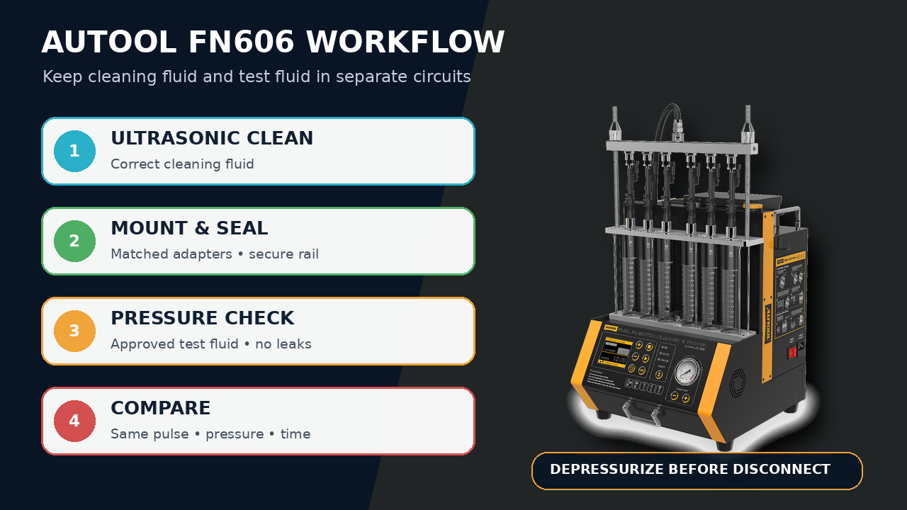
Quick answer: Remove and identify the gasoline injectors safely, clean them in approved ultrasonic fluid, then mount up to six compatible injectors on the FN606. Use approved test fluid, verify sealing at controlled pressure, compare spray and volume under identical settings, and return pressure to zero before disconnecting.
In this guide
Before you start
Injector service combines flammable-vapor risk, pressurized liquid and electrically driven components. Work in a grounded, ventilated area with no smoking, flame, spark-producing tool or hot surface. Relieve vehicle fuel pressure and remove the injectors by the exact vehicle procedure before using the bench.
- confirm the model label reads AUTOOL FN606, the delivered mains input matches the outlet and the bench provides one pump across the six-position bench;
- identify every injector by cylinder and verify injector type, impedance, drive voltage, adapter and service limits from reliable vehicle or injector data;
- inspect the detachable ultrasonic tank, measuring cylinders, test rail, seals, electrical leads, splash guard, pump circuit and drain path;
- prepare approved ultrasonic cleaning fluid and approved non-corrosive injector test fluid in separate labeled containers—never gasoline;
- confirm all measuring cylinders are empty and readable and the recovery container has enough capacity; and
- wear eye protection and fluid-resistant gloves, with spill control and a suitable fire plan available for the work area.
Use the AUTOOL manual download center to locate the current instructions when a manual is available. The delivered model label and current vehicle service information control if an older image or remembered setting differs.
FN606 controls and specifications
The current product record highlights Six-injector comparison, Detachable heated ultrasonic tank, Extended voltage control, Advanced pulse control, Single-pump test circuit. Confirm each relevant control on the physical unit before use; related AUTOOL models can look similar while using different ranges, air sources or operating modes.
| Specification or function | Current model |
|---|---|
| Power Input | 110/220V; match the delivered unit label |
| Cleaning and Test Modes | 3 cleaning functions + 12 testing functions |
| Injectors Tested at Once | 6 compatible fuel injectors |
| Supported Injector Types | Standard, GDI, EFI and FSI long fuel injectors |
| Injector Drive Voltage | 12V; adjustable 12-70V; 120-180V |
| Ultrasonic Tank Capacity | 550 mL detachable tank |
| Heated Ultrasonic Cleaning | Included; up to 50°C |
| Pulse Width Range | 0-40 ms; 0.1 ms steps |
| Simulated Speed Range | 0-7500 rpm |
| Measuring Tube Capacity | 110 mL each |
The current first-party table lists six-injector capacity, a detachable 550 mL tank heated up to 50°C, 0-40 ms pulse width, 0-7500 rpm simulation and 12V, adjustable 12-70V and 120-180V drive ranges. These are machine capabilities, not universal injector settings. The injector data and delivered instructions determine the permitted voltage, pressure, pulse and time.
How to use the FN606
Step 1: Remove and identify the injectors safely
Work in a ventilated area with no smoking, flame, spark-producing tool or hot surface. Relieve vehicle fuel pressure by the OEM procedure, disconnect power, remove the gasoline injectors, cap open vehicle lines and label each injector by cylinder. Confirm the injector type, electrical requirement and permitted bench adapter before it approaches the machine.
Before moving on, confirm vehicle fuel pressure is relieved, every injector is identified, no ignition source is present and gasoline has not been selected as bench test fluid.
Step 2: Inspect the FN bench and separate the two fluids
Confirm the exact FN606 label, delivered mains input, detachable 550 mL ultrasonic tank, six measuring cylinders, rail, electrical leads, adapters, drain path and splash guard are clean and undamaged. Keep ultrasonic cleaning fluid separate from manufacturer-approved injector test fluid; never use gasoline as bench test fluid.
Step 3: Prepare the injectors for ultrasonic cleaning
Remove replaceable filter baskets, O-rings or caps only as the injector service procedure requires. Suspend or connect the injector bodies so the required working section is exposed to cleaning fluid without submerging an electrical connector that must remain dry. Add enough approved ultrasonic cleaning fluid before enabling ultrasound; never run the tank dry.
Step 4: Select heat, pulse and cleaning time from known limits
Use heating only when the cleaning fluid and injector procedure permit it, and never exceed the FN platform’s stated 50°C limit. Select the injector drive setting from verified injector data; use 12V for a compatible conventional injector and use the adjustable 12-70V or 120-180V ranges only when the exact injector requires them. Do not discover voltage by trial.
Step 5: Run the cleaning cycle and monitor every injector
Start the documented ultrasonic or pulse-assisted cleaning function and observe the tank continuously. Stop for unusual noise, overheating, arcing, a loose electrical connection, falling fluid level or fluid contacting an unapproved area. Allow the injectors and cleaning fluid to cool before moving to the test bench.
Step 6: Mount equal injectors on the test rail
Install up to six compatible injectors with the correct adapters and fresh service seals where required. Align each injector over its 110 mL measuring cylinder, lock the rail evenly and fit the splash guard. Tug-check the rail and every adapter before adding test fluid or pressure.
Step 7: Fill the test circuit and establish safe pressure
Add only approved non-corrosive injector test fluid to the designated test-fluid circuit, confirm the drain is closed and prime the circuit by the current machine instructions. The FN606 uses one test-fluid pump for the complete six-position bench. Raise pressure only to the injector or service specification while watching every seal and connection.
Step 8: Check sealing before dynamic testing
With the injectors commanded closed under the specified test pressure, look for drips at each nozzle and leakage at every temporary adapter. Stop and depressurize for an external connection leak. Record a nozzle leak separately from an adapter leak; do not continue a spray test through an unsafe seal.
Step 9: Compare spray pattern and delivered volume
Choose only a labeled current test mode, then set time, simulated speed and pulse width within the injector specification and the FN ranges. Start at a conservative condition, observe atomization and pulse response, and compare all cylinders under the same setup. Let the cycle finish before reading fluid volumes at eye level.
Step 10: Repeat, depressurize, drain and preserve the result
Repeat an unexpected result after swapping or reseating one controlled variable, not after changing several settings at once. When testing is complete, stop the pumps, return pressure to zero, switch off and disconnect power before loosening the rail. Drain test and cleaning fluids into labeled containers, clean the tank and lines, reinstall service parts and preserve the injector-to-cylinder result map.
Before touching the rail or a hose, confirm the pumps are stopped, pressure reads zero, mains power is off and both fluids are routed into their correct labeled recovery containers.
Read and verify the result
Compare only injectors tested with the same adapters, pressure, pulse width, time and simulated condition. Read volume at eye level after flow settles, and pair it with spray shape, atomization, response and closed-nozzle leakage. One attractive spray image without a controlled volume comparison is incomplete evidence.
- A leaking temporary adapter is a setup fault; a nozzle drip with a sealed rail is an injector observation. Record them separately.
- Swap or reseat one controlled variable when a result is unexpected. If the difference follows the bench position, inspect that position before condemning the injector.
- Compare left and right FN608 rail groups only after confirming both pump circuits use equivalent settings and stable flow.
- Preserve the injector-to-cylinder map so a cleaning or replacement decision remains traceable when parts return to the vehicle.
Stop for fuel odor, vapor, arcing, fluid leakage, a loose rail, abnormal pump noise, pressure that will not stabilize, an empty ultrasonic tank, overheating or test fluid approaching a cylinder limit. Switch the function off, return pressure to zero and disconnect mains power before touching the rail or hoses.
Common mistakes and care
- Use only removed gasoline injectors whose type, voltage and adapters are confirmed for the exact FN setup.
- Keep fuel vapor, gasoline, flame, smoking and spark-producing equipment out of the work area.
- Use approved ultrasonic cleaning fluid in the cleaning tank and approved non-corrosive test fluid in the test circuit; never substitute gasoline.
- Do not run the ultrasonic tank dry or exceed the stated 50°C heating limit.
- Depressurize the test circuit completely before moving the rail, hose, adapter or injector.
- Do not use gasoline as bench test fluid or mix ultrasonic cleaning fluid into the pressure-test circuit.
- Do not guess an injector voltage from connector shape, vehicle brand or another injector in the same family.
- Do not run ultrasound dry, exceed the 50°C limit or heat a fluid whose supplier does not permit it.
- Do not loosen an injector, rail or hose while the gauge or machine indicates pressure.
- After service, drain and clean the machine as directed and store fluids in correctly labeled approved containers.
Frequently asked questions
Can I use gasoline as test fluid in the FN606?
No. Use only the approved non-corrosive injector test fluid identified by the current machine guidance. Keep gasoline and its vapor out of the bench test circuit and work area.
Which injector drive voltage should I select?
Use verified injector or vehicle service data. The available 12V, adjustable 12-70V and 120-180V ranges are not a trial sequence; the wrong voltage can damage an injector or produce a misleading result.
Should I clean or test first?
For a normal cleaning service, preserve an initial observation when needed, clean the injectors, then perform the controlled sealing, spray and volume comparisons. Keep all post-cleaning test conditions identical across the set.
Final FN606 checklist
- Vehicle fuel pressure relieved; injectors removed and mapped by cylinder
- Exact injector type, adapters, drive voltage and limits confirmed
- Cleaning fluid and test fluid kept separate; gasoline excluded
- Rail secured and seal check completed before dynamic testing
- Spray, leakage and volume compared under identical settings
- Pressure returned to zero; machine drained, cleaned and powered off
Used this way, the FN606 turns injector cleaning into a controlled comparison. Clean first, prove the temporary seals, preserve identical test conditions and carry the cylinder map back to the vehicle diagnosis.


Comments 0
Questions, fixes, and real-world diagnostic notes from readers.
Be the first to share a diagnostic result or ask a follow-up question.