
How to Use the FXTUL UNT60 Fuel Injector Cleaner and Tester

The FXTUL UNT60 cleans compatible removed motorcycle fuel injectors in an ultrasonic bath, then uses a separate pressurized test-fluid circuit to observe leakage, spray behavior and relative delivery. The safe sequence is clean, isolate, change to the test setup, pressurize to the injector’s documented condition, run only the relevant program, record the result, depressurize and drain.
Keep the two liquids separate. Dedicated ultrasonic cleaning agent belongs in the open bath; approved injector testing agent belongs in the reservoir, pump, test rail and glass cylinders. Neither fluid is gasoline, kerosene or an unidentified solvent, and a number printed as a machine range or manual example is not automatically the correct setting for your injector.
Updated August 28, 2026.
In this guide
Decide whether the UNT60 fits the job
| Situation | Decision | Why |
|---|---|---|
| Up to two removed motorcycle port-fuel injectors fit the supplied top-feed adapters, electrical leads and 0–0.6 MPa machine range | Continue after checking injector service data | UNT60 can clean and compare compatible injectors under controlled off-vehicle conditions |
| The injector is direct-injection, side-feed, piezoelectric or otherwise not expressly supported by the adapters and drive | Stop | Physical fit alone does not prove electrical, pressure or material compatibility |
| The injector is still on the vehicle or fuel pressure has not been relieved | Use the vehicle service procedure first | UNT60 is an off-vehicle cleaner and tester, not an on-car flushing machine |
| You do not have the injector’s required pressure, pulse width or evaluation limit | Obtain service data or use qualified injector service | A copied display value can produce a misleading result or damage a component |
| The machine label does not match the grounded supply | Do not connect power | This manual edition lists 220 V ±10% at 50 Hz; the delivered unit’s rating plate always controls |
| A glass cylinder, cord, hose, O-ring, adapter, lead or machine case is damaged | Do not operate | The job combines mains power, liquid and pressure |
Understand the controls and programs before filling
The upper display shows the selected function and pulse width. The lower display shows working time or injection count. The left arrow pairs change pulse width and time/count; the center buttons start, pause and stop; the right arrows select a function. The pressure knob changes test-circuit pressure only after the pump is running. Turn it gradually and read the gauge—never use knob position as a pressure measurement.
| Program | Purpose | What it can show |
|---|---|---|
| 01 | Ultrasonic cleaning | Pulsed injector actuation while the lower injector section is in dedicated bath cleaner |
| 02–04 | Idle, medium and high simulated-speed tests | Spray behavior at three steady programmed conditions |
| 05 | Accelerating test | A repeating rise through simulated speed |
| 06 | Variable-speed test | Repeating idle, medium and high simulated conditions |
| 07 | Leakage test | Whether fluid escapes when the injector should remain sealed under the specified test condition |
| 08–10 | Idle, medium and high spray-volume tests | Relative delivered volume collected in the two cylinders under identical settings |
| 11 | Unit information | Machine information, not an injector test |
The UNT60 can display pulse widths from 0 to 20.0 ms, pressure from 0 to 0.6 MPa, a timer up to 20 minutes and simulated speed up to 7500 rpm. Those are equipment capabilities. Use the injector or vehicle manufacturer’s test conditions and limits whenever they exist.
Prepare the machine, injectors and fluids
Have the exact vehicle fuel-system procedure, injector specifications, eye protection, fluid-resistant gloves, absorbent material, a stable labeled waste container, approved replacement O-rings, a material-compatible O-ring lubricant, dedicated ultrasonic injector cleaner and dedicated injector test fluid. Read both fluid labels for ventilation, contact time, filtration, reuse and disposal.
Place the UNT60 upright on a stable, level, dry bench in a ventilated area. Keep ignition sources away. The manual specifies 0–40°C, relative humidity below 85% and no open flame. Keep the plug, outlet, switches, leads and machine exterior dry throughout the job.
FXTUL UNT60 step-by-step procedure
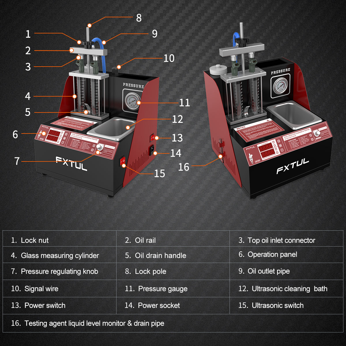
Step 1: Confirm the exact machine and power rating
Read the machine label and confirm UNT60. Match its voltage and frequency to a grounded outlet. Do not infer dual-voltage capability from a marketing image: this manual edition lists 220 V ±10% and 50 Hz, while the unit in front of you is the final authority.
Identify the bath, glass cylinders, cylinder drain/return handle, test rail, locking pole, outlet hose, signal leads, pressure gauge, pressure knob, side sight/drain tube, main power switch and separate ultrasonic switch.
Completion check: The power is still disconnected, the rating matches the supply and you can distinguish every wet-path control.
Step 2: Relieve pressure and remove the injectors through service information
Follow the vehicle manufacturer’s procedure to relieve fuel pressure, isolate power where required, disconnect the rail and remove the injectors. Cap open vehicle fuel connections and move liquid fuel away from the UNT60 bench.
Do not guess a fuse, pressure-relief point, connector latch, rail order or torque from this guide. Those details vary by motorcycle and engine.
Stop: If fuel continues to escape, an injector is seized, or exact removal information is unavailable, do not proceed at the machine.
Step 3: Identify and label each injector
Record cylinder location before cleaning. Inspect the body, electrical pins, inlet, outlet and filter area. Measure coil resistance if the controlling service procedure requires it. Set aside any cracked, corroded, burnt or electrically out-of-range injector rather than assuming cleaning will repair it.
Remove or retain O-rings, caps and filters only as the injector service procedure directs. Plan new approved seals for reinstallation; a test-bench seal is not automatically a reusable vehicle seal.
Common mistake: Mixing injector positions before the baseline condition and cylinder assignment are recorded.
Step 4: Inspect the UNT60 and choose the correct adapters
With both switches off and the cord unplugged, inspect the bath, cylinders, gauge, hoses, side sight tube, rail, locking hardware, adapters, signal leads, cord and case. A chipped or cracked measuring cylinder, swollen hose, cut O-ring or loose electrical part is a stop condition.
Dry-fit each injector to the cleaning support and intended top-feed test adapter. It must seat squarely without forcing the connector or loading the injector body sideways.
Completion check: Two injectors, their original positions and every required adapter are positively identified.
Step 5: Keep the cleaning and testing fluids separate
Label one container ultrasonic cleaner and the other injector test fluid. Confirm that each product is approved for its circuit and compatible with the injector materials. Never put gasoline or kerosene in the UNT60. Do not substitute alcohol or another workshop liquid unless the exact current UNT60 and fluid manufacturer instructions expressly approve it.
Keep the pressure circuit drained or isolated while using the open bath. Do not pour test fluid into the bath and do not pour used bath cleaner into the side fill/sight tube.
Critical check: If a liquid cannot be positively identified, do not use or reuse it.
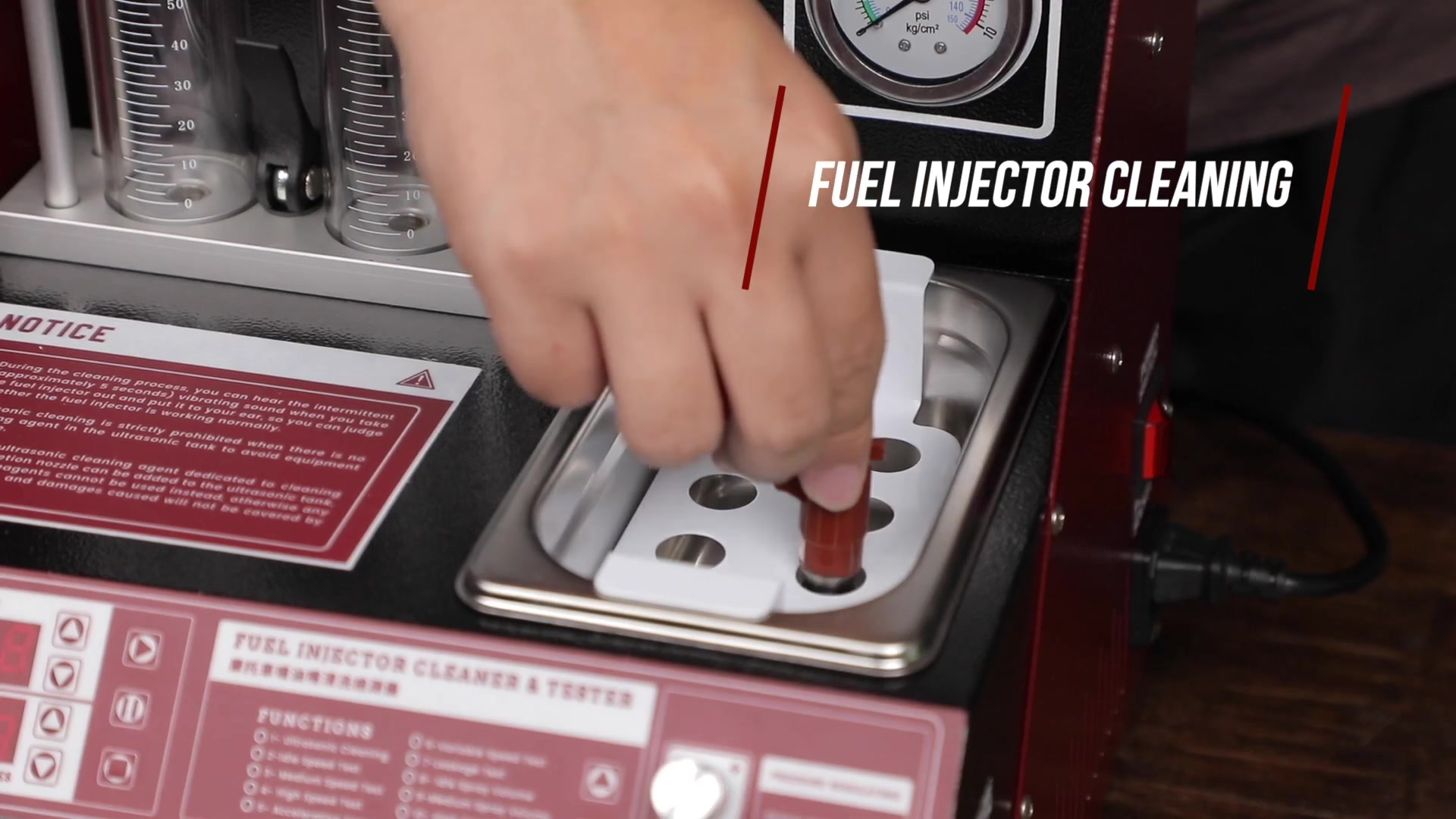
Step 6: Install the cleaning support and pulse leads with power disconnected
Mount the cleaning support over the ultrasonic bath. Seat each compatible injector so the working end will reach the cleaning zone while the electrical connector remains above the liquid. Connect the matching pulse lead by its connector body; never pull the wire or force misaligned pins.
Route leads so they cannot fall into the bath or be trapped by the bracket. Keep all external connectors dry.
Completion check: Injectors are secure, connectors are dry and no lead carries the injector’s weight.
Step 7: Add only dedicated ultrasonic cleaning agent
Pour dedicated injector ultrasonic cleaner slowly into the bath. Cover the lower working portion supported for cleaning, without submerging electrical connectors or exceeding the fluid maker’s immersion boundary. The bath capacity is 1300 ml, but capacity is not a fill target.
Wipe splashes from the machine and bench. Confirm liquid is present before the ultrasonic switch can be used; never run an empty bath.
Stop: If liquid reaches a connector, switch or the exterior electrical area, do not connect power until everything has been corrected and dried.
Step 8: Select program 01 and a controlled cleaning time
After the mechanical and liquid setup is complete and dry, connect the matching grounded supply and turn on the main power. Use the function arrows to select 01 Ultrasonic Cleaning. Set a duration permitted by the injector and cleaner instructions; the panel’s 20-minute range and the manual’s default are not universal prescriptions.
Press Start, then switch on the separate ultrasonic function. Confirm that the display counts normally and that the supported injectors remain stable.
Completion check: Program 01 is active, bath liquid covers only the intended wet section and all electrical connections remain dry.
Step 9: Monitor the full cleaning cycle from a normal working position
Watch for stable support, normal display behavior and contained liquid. Do not hold a vibrating injector next to your ear. Do not reach into the bath, touch a wet connector or leave the machine unattended.
Stop immediately for smoke, a burning smell, unusual impact noise, displaced injectors, leaking liquid, an abnormal display or loss of ultrasonic action. Turn off the ultrasonic switch, press Stop if responsive, turn off main power and unplug before touching the setup.
Common mistake: Extending time because contamination is visible. Repeated exposure must stay within the injector and fluid limits.
Step 10: End cleaning and isolate power before wet handling
When the timer completes, switch off the ultrasonic function, stop the program, turn off main power and unplug the cord. Allow motion and dripping to stop before lifting the support.
Remove the injectors by their bodies. Let excess cleaner drain back into the bath, then place each injector in its labeled clean tray. Keep electrical connectors dry and follow the cleaner instructions for rinsing or drying.
Completion check: The machine is unplugged, injectors remain identified and no bath liquid has entered the pressure circuit.
Step 11: Prepare the separate pressure-test circuit
Confirm the pressure knob is at minimum and the machine remains unplugged. Put the cylinder drain/return system in its normal fill/return condition so test fluid can circulate rather than collect unexpectedly. Confirm the glass cylinders are empty.
Using a clean funnel, add dedicated injector test fluid slowly through the test-circuit fill opening. The manual calls for about 1000 ml. Watch the side sight tube, prevent overflow and keep the fluid clean; do not treat 1000 ml as a reason to exceed the machine’s visible safe level.
Critical check: The pressure circuit receives approved test fluid only—not the bath cleaner, gasoline, kerosene or vehicle fuel.
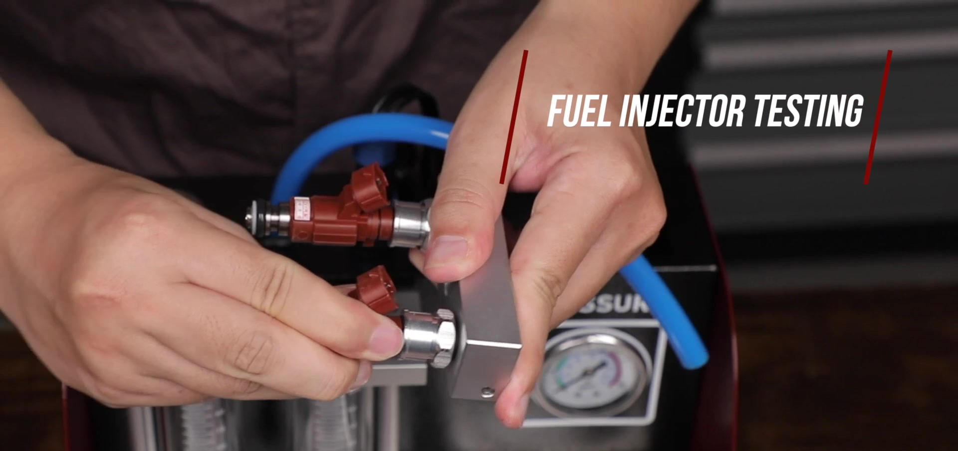
Step 12: Fit the top-feed adapters and seals
Choose the exact top-feed connectors that match the injector inlet. Inspect every adapter seal and injector O-ring. Apply only a light film of service-data-approved, test-fluid-compatible lubricant where the seal procedure permits it.
Insert each injector straight into its adapter without cutting or rolling the O-ring. Do not use the locking pole to force a mismatched injector into place.
Completion check: Both injectors seat to the same depth, seals are not pinched and the bodies are not under side load.
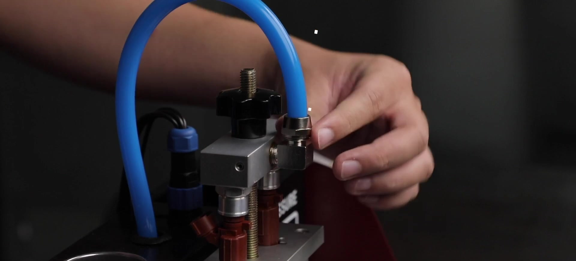
Step 13: Secure the test rail evenly
Install the adapters in the rail, place the rail and injector outlets squarely over the upper plate, and lower the locking bar. Tighten the two ends evenly until the assembly is secure. Excess force can damage an injector, adapter, rail or glass support.
Connect the blue outlet hose to the rail fitting and make sure its connector is fully seated. Route the hose without a kink, sharp bend or pull on the rail.
Completion check: The rail is level, the injectors align with the two cylinders and the hose cannot whip or detach.
Step 14: Connect the injector signal leads
Match each signal lead to its injector connector and push it straight into place. Keep the leads away from the bath and rail locking hardware. Reconfirm that the machine is dry before connecting power.
If a connector fits only under force or leaves exposed loose terminals, stop and obtain the correct adapter. An improvised electrical connection can produce a false comparison or damage the injector driver.
Completion check: Both connectors are fully supported and each injector still aligns over its own cylinder.
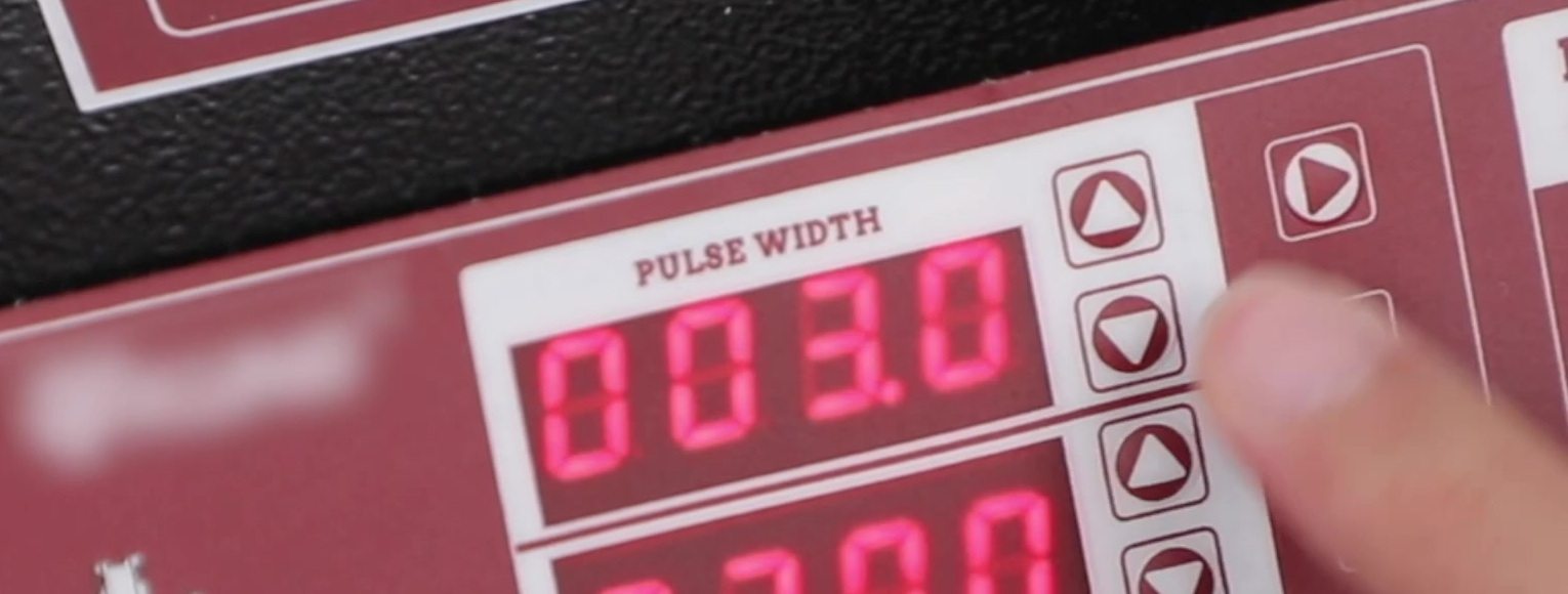
Step 15: Choose the test question before choosing a program
Use service information to decide what you need to learn. Choose 02–04 for a steady spray observation, 05–06 for changing simulated conditions, 07 for sealing under the specified condition, or 08–10 for comparative delivered volume. You do not need to run every program on every injector.
Enter the specified pulse width and test time or injection count. Apply the same valid settings to both injectors being compared. Do not copy values from a video frame or a previous injector family.
Completion check: The program, pressure target, pulse width, duration/count and acceptance method are written down before the pump starts.
Step 16: Start at minimum pressure and raise it slowly
Connect power, turn on the main switch and confirm the selected program. Press Start with the pressure knob at minimum. Turn the knob clockwise gradually while watching the gauge until the documented injector test pressure is reached. Stay within both the injector limit and the UNT60’s 0–0.6 MPa range.
Never tighten the rail, adapter or hose while pressurized. If pressure rises abruptly, cannot stabilize or exceeds the target, press Stop, return the knob to minimum, switch off and depressurize before inspection.
Critical check: Gauge pressure—not knob position, pump sound or a copied example—controls the test condition.
Step 17: Pass the external-leak and stability gate
Before judging an injector spray, inspect the rail, adapters, hose and injector joints for external leakage. Confirm that the rail stays level and the gauge is stable at the documented condition.
An external leak invalidates the test because fluid bypasses the injector and changes the delivered quantity. Stop, reduce pressure to minimum, switch off, unplug, relieve residual pressure and repair the seal before repeating.
Pass condition: No external liquid escapes and pressure is stable enough to run the selected program.
Step 18: Observe steady and changing spray programs
For programs 02, 03 or 04, observe both injectors from normal working distance under the same valid setting. Look for a stable pattern and a meaningful side-to-side difference; compare the result with the injector manufacturer’s expected pattern rather than a generic “good spray” picture.
Programs 05 and 06 automatically vary simulated conditions. Keep hands and face away from the test area, watch the rail and gauge, and pause if a cylinder is accumulating more liquid than expected.
Stop: Dripping, a distorted pattern or unequal behavior is evidence for diagnosis, not permission to increase pressure beyond specification.
Step 19: Run the leakage test only at the specified condition
Select 07 Leakage Test, enter the documented time and establish the specified pressure through the controlled start procedure. Observe whether either injector passes fluid when it should remain closed. Distinguish injector-tip leakage from an adapter or O-ring leak above it.
Do not use a universal one-minute or 0.3 MPa rule merely because it appears as a manual example. Record actual pressure, time, injector position and observed leakage so the result can be repeated.
Pass condition: Evaluate sealing against the exact injector specification; if none is available, report the observation without inventing a pass/fail limit.
Step 20: Configure a spray-volume comparison
For programs 08, 09 or 10, empty the cylinders first and set the drain/return handle to retain test fluid in them. Reconfirm equal injector installation, the same pressure, pulse width and injection count, and a level machine.
Start the selected volume program and watch both cylinder levels continuously. Stop or pause before either cylinder reaches two-thirds full. Never allow a test to overflow merely to complete a preset count.
Completion check: Both cylinders contain a measurable amount below the two-thirds stop line under the same documented condition.
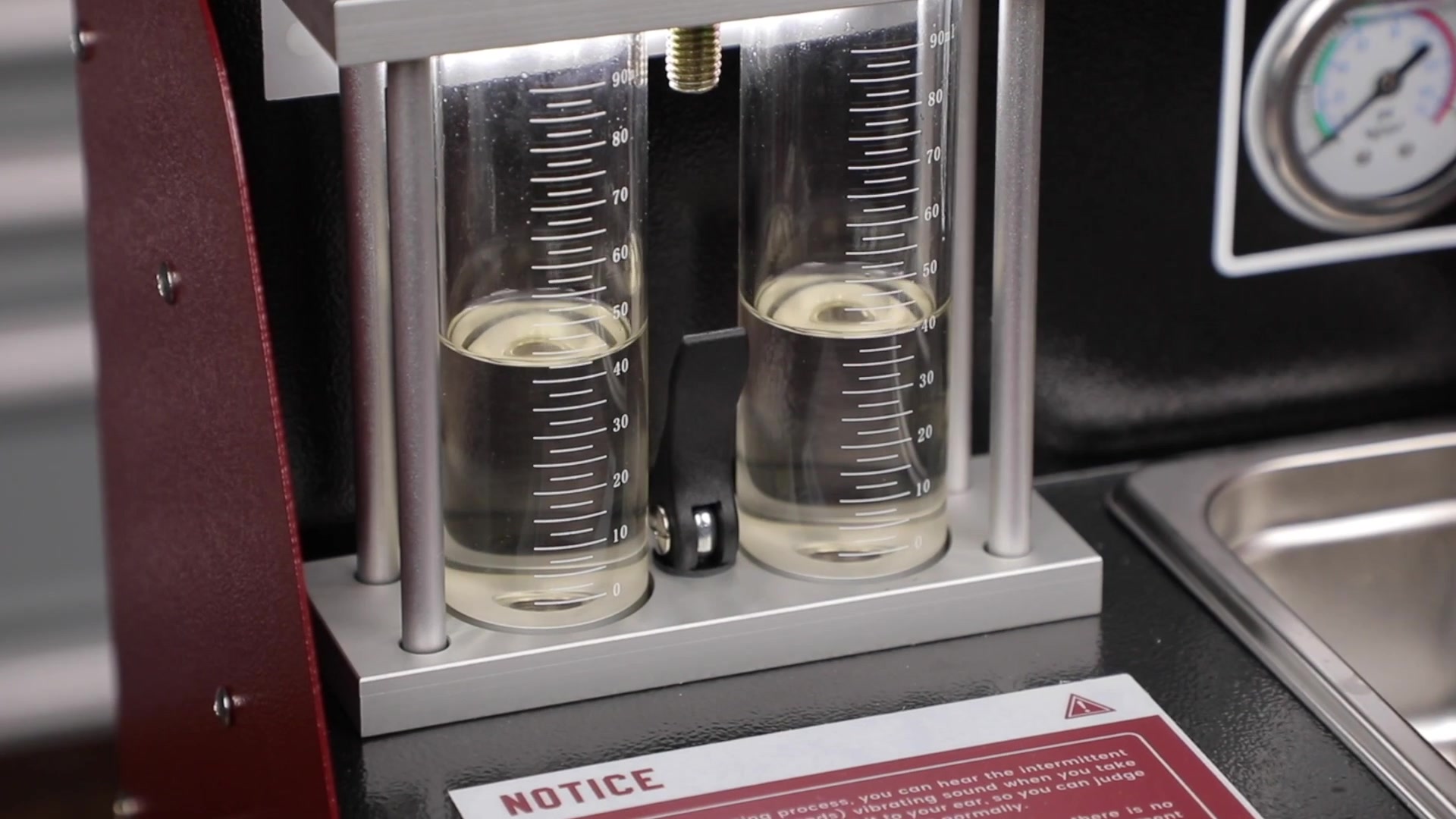
Step 21: Read the cylinders without overclaiming the result
Let foam and splashing settle, then read each meniscus at eye level on the same part of the scale. Record both volumes and calculate the difference using one stated method. The manual mentions a generic 2% same-vehicle comparison, but the injector or vehicle manufacturer’s current limit controls whenever available.
Similar volume does not prove correct atomization, sealing, electrical response or on-vehicle performance. Combine volume with the leakage and spray observations and the original vehicle diagnosis.
Common mistake: Calling two nearly equal cylinders “repaired” without checking that both injectors also meet the required absolute delivery and other specifications.
Step 22: Depressurize before loosening any wet connection
Press Stop. Turn the pressure knob fully back to minimum and confirm the gauge returns to zero. Turn off main power and unplug the cord. Operate the return/drain control only as needed to release and return captured test fluid through its intended path.
Do not loosen the rail, hose or adapter while the gauge shows pressure. Use absorbent material around connections, keep injectors labeled and remove the locking load evenly.
Critical check: Zero gauge pressure, power off and plug disconnected are all required before disassembly.
Step 23: Drain, clean, evaluate and record the job
Return reusable test fluid to its clean dedicated container only when the fluid maker permits it and no contamination is present. Otherwise drain it into a labeled waste container. Never return bath cleaner to the test-fluid container. Drain and wipe the ultrasonic bath, clean the cylinders and exterior with approved methods, and store the dry machine upright.
Inspect injector seals and follow exact vehicle service information for new O-rings, lubrication, installation, torque, reconnection, priming and a fuel-leak check. Record injector positions, fluid identities, pressure, pulse width, program, duration/count, leakage, spray observations and measured volumes.
Completion check: The machine is depressurized, unplugged, drained and dry; injector results are documented; and vehicle reinstallation remains controlled by the correct service procedure.
How to interpret the result
Use a matrix rather than a single judgment. A leakage failure points to sealing trouble. Unequal volume under identical valid conditions points to delivery imbalance. An abnormal pattern can remain even when volumes are similar. An electrically out-of-range injector is not repaired by a visually improved spray.
If a repeat test is justified, repeat it with the same injector positions or intentionally swap positions and document the swap. A difference that follows the injector is more meaningful than one that remains with a machine channel, adapter or cylinder. Stop repeating cycles when the injector or fluid exposure limit is reached.
Troubleshooting the UNT60 workflow
| Symptom | Check first | Safe next action |
|---|---|---|
| No display | Matching supply, plug, switch and exact replacement fuse | Unplug before fuse inspection; never open the case |
| Pump runs but pressure will not build | Fluid level, return/drain position, hose, rail and adapter seals | Stop, return pressure to minimum, unplug and correct the fluid path |
| Pressure is unstable | External leak, low/dirty test fluid, restricted path or pump condition | Do not interpret injector results until pressure is stable |
| One cylinder fills faster | Equal settings, injector position, adapter seal and channel condition | Record, depressurize and repeat with a documented position swap if appropriate |
| No ultrasonic action | Bath has approved cleaner, ultrasonic switch is on and program 01 is active | Stop and unplug if behavior remains abnormal; do not run the bath empty |
| Test fluid is dirty | Reservoir and circuit contamination | Drain, rinse with a small amount of approved test fluid as directed, then refill with about 1 L of fresh agent |
| Glass is cracked or chipped | Physical inspection | Stop using the machine until the exact replacement is installed |
Finish with evidence, not assumptions
A complete UNT60 job leaves three kinds of evidence: controlled settings, observable results and a safe machine state. Record the exact injector, pressure, pulse width, program and result; keep cleaning fluid separate from test fluid; and finish at zero pressure with the power disconnected. That makes the next diagnostic or service decision traceable instead of relying on a copied setting or a general impression.


Comments 0
Questions, fixes, and real-world diagnostic notes from readers.
Be the first to share a diagnostic result or ask a follow-up question.