
How to Use the AUTOOL LM70 Digital Manifold Gauge

Use the AUTOOL LM70 by identifying the vehicle refrigerant, closing both manifold valves, inspecting every hose and coupler, installing three AAA batteries, selecting the matching refrigerant and units, and zeroing the disconnected manifold in open air. Connect it only through the vehicle’s A/C service procedure. Read low- and high-side pressure together with the two pipe temperatures, then compare the complete data set with the specified test condition—not with a universal pressure chart.
The LM70 is a dual-channel digital refrigerant manifold. It can display pressure, pressure-derived saturation temperature, two probe temperatures, calculated superheat and subcooling, a timed pressure-change screen, and relative vacuum information. It cannot identify refrigerant, choose the correct service ports, supply a vehicle’s target charge, prove that a system is leak-free, or confirm deep dehydration by itself.
Updated August 27, 2026.
In this guide
What the LM70 does
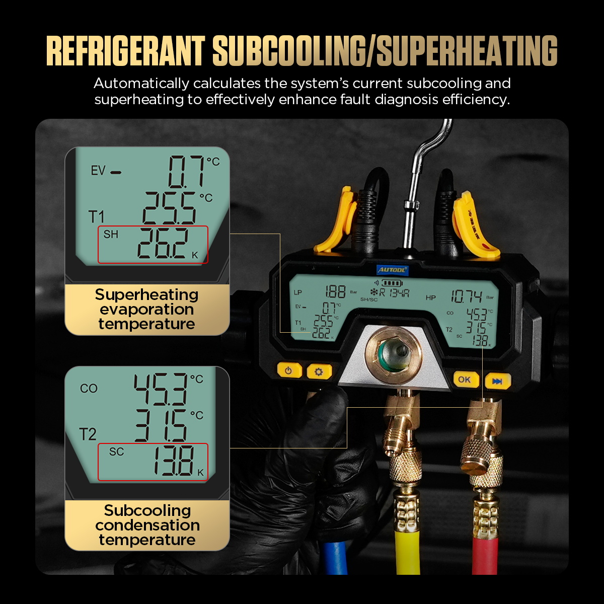
The AUTOOL LM70 combines low- and high-side pressure channels with two wired temperature-probe inputs. In Refrigeration mode, its screen identifies LP and HP pressures, EV and CO saturation values, T1 and T2 measured pipe temperatures, and SH and SC calculated values.
Its menu contains pressure-temperature data for 16 refrigerants: R410A, R407C, R404A, R22, R134A, RH2O, R11, R12, R13, R13B1, R14, R114, R1150, R123, R1233ZD, and R1234YF. A refrigerant appearing in that menu means the meter can reference its pressure-temperature relationship; it does not confirm that every hose, coupler, oil-control method, recovery machine, or charging procedure is suitable for that system.
The manual lists a 0–870 psi relative pressure range, a -55°C to 125°C probe range, relative vacuum units, and three-AAA battery power. Treat the lowest-rated hose, coupler, adapter, instrument, recovery device, and system component as the actual limit. Never use a display range as permission to exceed the equipment procedure.
Before you start
Open the AUTOOL manual download center and match the LM70 manual to the instrument in front of you. Obtain the exact vehicle A/C service procedure, verified refrigerant identity and specified operating test. Prepare compatible service couplers, rated hoses, recovery and evacuation equipment, any required charging scale and absolute vacuum gauge, three fresh AAA batteries, eye and hand protection, and a job sheet.
Refrigerant service can cause frostbite, eye injury, high-pressure release, oxygen displacement, environmental harm, and damage from incorrect oil or refrigerant mixing. Work in a ventilated area. Keep hoses away from belts, fans, exhaust components and electrical terminals. Expect an electric fan to start without warning.
Stop: Do not connect an unknown refrigerant system, a visibly damaged service port, a system above the lowest component rating, or a vehicle for which you lack the correct recovery and service method. Do not vent refrigerant. Do not use air or oxygen to pressure-test a refrigerant circuit. Follow applicable certification, recovery, approved test-gas and refrigerant-handling requirements.
Understand the LM70 controls and display
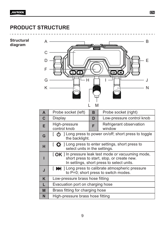
The left and right top sockets accept temperature probes. The blue-side knob controls the low-side path and the red-side knob controls the high-side path. Across the bottom are the low-side fitting, center charging/evacuation fitting, and high-side fitting. The center sight window helps the operator observe flow, but it is not a charge-quantity measurement.
The four buttons work as follows:
- Power: long press to turn the LM70 on or off; short press to toggle the backlight.
- Settings: long press to open settings; short press advances through the settings fields.
- OK: selects settings and starts, stops, or resets a timed test.
- Mode/zero: short press changes operating mode; long press performs atmospheric pressure zeroing.
The main display also shows the chosen refrigerant, measurement units, battery level, mode, time and difference fields. Read the labels on the exact delivered screen rather than memorizing a different manifold’s key sequence.
LM70 step-by-step operating procedure
Step 1: Define the A/C service task
Decide whether the job is a running-system pressure and temperature check, an approved isolated pressure-decay test, or an evacuation observation. Write down the vehicle, refrigerant, service-port arrangement, required equipment, operating condition, target values, stabilization time and finish procedure.
Do not combine tasks casually. A running pressure test, a nitrogen pressure test, evacuation and charging use different system states and controls. The LM70 mode does not make an unsafe system state acceptable.
Completion check: The exact refrigerant, test purpose, connection diagram, limits and acceptance method come from reliable vehicle or equipment information.
Step 2: Inspect the manifold, hoses, and couplers
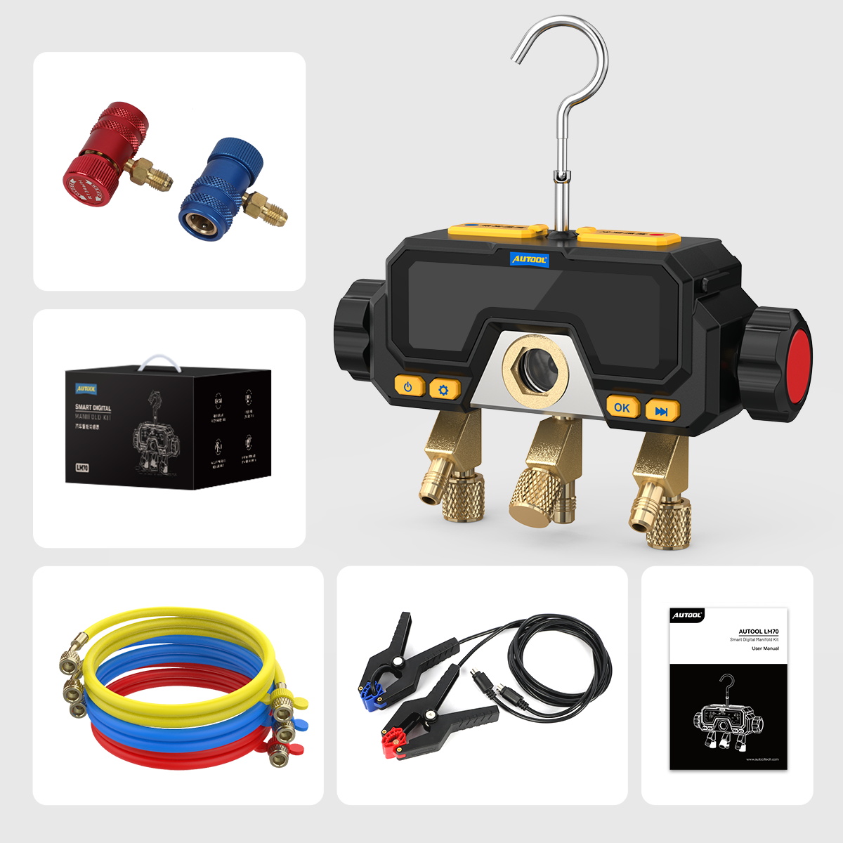
Start with both LM70 control knobs fully closed. Inspect the housing, sight window, hook, screen, battery cover, probe sockets, brass threads and valve action. Check hoses along their full length for cuts, blistering, hardening, oil-soaked areas, damaged seals and loose crimps. Confirm each coupler matches the identified refrigerant and service port.
Replace a questionable hose rather than tightening harder. If the manifold has been dropped or mechanically loaded, the manual requires technical evaluation and replacement of affected hoses because internal damage may not be visible.
Stop: Do not use a cracked housing, leaking valve, damaged thread, unreadable screen, suspect coupler or hose whose working rating is below the job requirement.
Completion check: Every pressure-containing part is compatible, intact, clean, closed and rated for the intended task.
Step 3: Install three AAA batteries
Lift the foldable hook and open the rear battery compartment. Install three 1.5 V AAA batteries using the polarity marks, then close the cover securely. Use a matched battery set and remove it before extended storage.
Long-press Power to start the manifold. Confirm the startup screen, battery indicator, complete display segments and button response. A flickering or unclear display can indicate depleted batteries.
Completion check: The LM70 starts normally, the battery icon is adequate for the job and the complete display is readable.
Step 4: Verify both valves are closed and ports are open to atmosphere
Before zeroing, keep the low- and high-side knobs closed and leave the pressure inputs disconnected at atmospheric pressure. Remove only clean protective caps needed for zeroing; prevent dirt or liquid from entering the fittings.
Zeroing a connected or trapped-pressure manifold offsets the reference incorrectly. Do not try to correct a live-system reading by pressing zero.
Completion check: No hose or coupler is applying pressure or vacuum to either measurement channel.
Step 5: Select refrigerant and measurement units
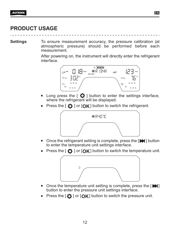
Long-press Settings. Use the selection keys to choose the exact refrigerant identified from the vehicle, then advance through temperature, pressure and vacuum units. Match all units to the service procedure and job sheet. Set the 30-minute automatic shutdown and sound option only after considering whether an unattended screen change could affect the task.
The menu spelling RH2O refers to water in the device list. Never select a refrigerant because its pressures appear close to an expected number. A wrong selection corrupts EV, CO, SH and SC even when the pressure sensors themselves are responding.
Completion check: The displayed refrigerant and units exactly match the verified service information before any connection.
Step 6: Zero pressure at atmosphere
With the manifold still disconnected, enter Refrigeration mode and long-press the Mode/zero key. The display shows P=0 while both pressure channels establish their atmospheric reference. Wait until the zero indication disappears.
Confirm LP and HP return to zero within the normal display behavior before continuing. If either channel remains offset, recheck for trapped pressure, contamination, temperature shock, damage or a calibration issue. Do not connect the vehicle until the cause is resolved.
Completion check: Both channels have been zeroed in open air immediately before the measurement.
Step 7: Hang the LM70 and plan hose routing
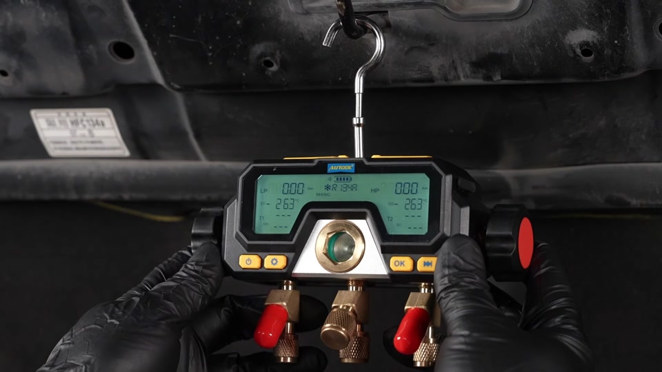
Hang the LM70 upright from a stable support with the display facing the observation position. The hook notch faces down when raised. Keep the instrument and every hose away from moving belts, pulleys, cooling fans, exhaust heat, sharp edges and energized terminals.
Lay out each hose without a tight bend or a route that can be pulled when the hood, fan, engine or technician moves. The center line should reach the required recovery, evacuation or service equipment without side-loading the manifold fitting.
Completion check: The LM70 stays upright, readable and clear of hazards through the complete planned procedure.
Step 8: Attach temperature probes before measurement
Connect the low-side pipe-temperature probe to the left socket and the high-side probe to the right socket according to the exact instrument diagram. Attach each clamp to the pipe location specified by the vehicle procedure—commonly a suction-side and liquid-side measurement point, but never assume location from color alone.
Use a clean, straight pipe section that gives secure contact. Keep the probes away from exhaust heat and moving parts. The manual says the probes must be connected before starting measurement for temperature to display.
Completion check: T1 and T2 correspond to documented pipe locations, the clamps are stable, and their leads are safely routed.
Step 9: Connect service hoses using the vehicle procedure
With the engine and A/C in the safe state specified by the service information, connect the blue and red service paths to the identified low- and high-side ports. Follow the coupler manufacturer’s locking method and the vehicle procedure’s connection order. Connect the center hose only to the recovery, vacuum, approved test-gas or charging equipment required for the current task.
Manage air in hoses using the approved service method. Do not loosen a hose to vent refrigerant as a generic purge technique. Keep both LM70 valves closed until the procedure explicitly calls for flow through the corresponding path.
Stop: If a coupler will not seat without force, a port leaks, the refrigerant identity becomes uncertain, or pressure appears on the wrong side, isolate the equipment and correct the setup.
Completion check: Each color path is physically traced to the correct port and destination, with no uncontrolled release and no open valve.
Step 10: Read the refrigeration screen as one data set
Place the vehicle in the exact specified test condition from a safe position. Let pressures, airflow, temperatures and compressor control stabilize for the required time. Read LP and HP together with EV and CO. If the probes are fitted correctly, record T1 and T2 and the displayed SH and SC.
EV and CO are saturation values calculated from measured pressure and the selected refrigerant dataset. SH and SC depend on those values and on correctly placed pipe probes. A plausible number can still be wrong if the refrigerant selection, probe location, airflow, engine speed, ambient condition or compressor state is wrong.
Record the complete operating condition: ambient temperature, vent or cabin condition when required, engine speed, blower/load, fan state, compressor command, LP, HP, EV, CO, T1, T2, SH and SC. Do not diagnose charge from one pressure or one temperature.
Completion check: Every recorded value belongs to one stable test state and can be compared directly with the vehicle procedure.
Step 11: Decide whether the reading is trustworthy
First check whether both pressures respond logically when the test state changes and return to a repeatable stabilized condition. Then confirm both probes remain firmly attached and that the selected refrigerant and units did not change. Compare the complete set with the specified test window.
An unexpected value can result from connection error, closed coupler, hose restriction, wrong refrigerant selection, poor probe contact, airflow fault, compressor control, contamination, noncondensables, overcharge, undercharge or an internal component problem. Use the vehicle diagnostic sequence to separate them.
Completion check: Setup and test-condition errors have been ruled out before any system conclusion is made.
Step 12: Use Pressure Leak Test mode only in an approved test
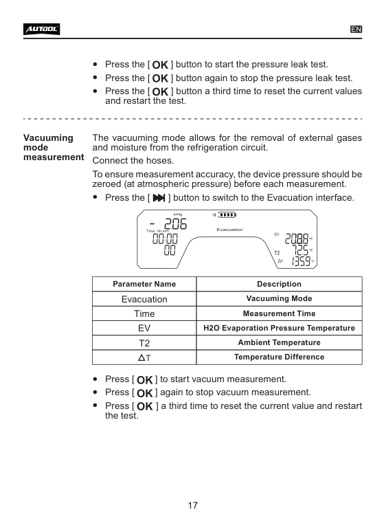
Use the short Mode/zero press to reach Pressure Leak Test only after the circuit has been isolated and brought to the specified test pressure with the approved test gas and regulator defined by the service procedure. Zero the disconnected manifold before the test—not after pressure has been applied. Press OK to start timing, OK again to stop, and a third time to reset and begin a new observation.
Record starting pressure, ending pressure, elapsed time and temperature. A pressure change can come from a leak, temperature change, hose expansion, valve movement or connection loss. A stable display over a short interval does not prove that the system is leak-free; use the specified hold time and leak-location method.
Stop: Never use oxygen or compressed shop air in a refrigerant circuit, never exceed the lowest component limit, and never improvise a test pressure.
Completion check: Test medium, pressure, stabilization, duration and acceptance all match the approved procedure and the result includes temperature context.
Step 13: Use Evacuation mode as a controlled trend
Connect the center path to properly sized evacuation equipment using the service setup specified for the vehicle. Short-press Mode/zero until Evacuation appears. Press OK to start the timed observation, again to stop, and a third time to reset. The LM70 can show relative vacuum progress, time and related temperature fields.
Relative vacuum is useful for seeing gross evacuation progress, but many automotive procedures require an absolute micron target, decay test and dedicated vacuum measurement close to the system. Use that instrument and acceptance rule when specified. A vacuum display does not prove correct oil, correct refrigerant, correct charge mass or absence of every leak.
Completion check: Evacuation reaches and holds the vehicle-specified criterion using the required absolute measurement method, not merely a visually low LM70 value.
Step 14: Isolate, recover, disconnect, and store
Return the system and service equipment to the shutdown state required by the vehicle procedure. Close both manifold valves, isolate the source or recovery equipment, and account for refrigerant trapped in hoses using an approved recovery or low-loss method. Disconnect service couplers in the specified order and reinstall clean port caps to the required condition.
Power off the LM70. Inspect the fittings for oil or damage, wipe the exterior with a damp cloth and mild cleaner, keep solvents out of the housing, and keep threaded connectors clean. Store the manifold dry with hoses protected from contamination. The manual recommends yearly leak checking and calibration.
Completion check: No refrigerant was intentionally vented, the vehicle ports are restored, the job record is complete, and the clean dry tool is ready for controlled storage.
How to judge reliable LM70 data
| Gate | Pass condition | Repeat or stop when |
|---|---|---|
| Identity | Vehicle refrigerant and service procedure are verified | Selection is based on pressure resemblance or guesswork |
| Setup | Valves begin closed, both channels were zeroed open to atmosphere, and every hose is correctly traced | A channel was zeroed under pressure or connection identity is uncertain |
| Test condition | Airflow, load, engine/compressor state, ambient condition and stabilization time are known | Values are compared across changing conditions |
| Interpretation | LP, HP, EV, CO, T1, T2, SH and SC are evaluated together against vehicle data | One value is used as a universal charge or fault verdict |
Common LM70 problems
Pressure is not zero before connection
Confirm both pressure fittings are truly open to atmosphere and no hose traps pressure. Long-press the zero key again. Persistent offset after temperature stabilization can indicate contamination, damage or a calibration problem; stop rather than subtracting the error mentally.
T1 or T2 does not appear
Power down if safe, reseat the correct probe in its socket and inspect the lead and clamp. The manual identifies poor probe connection or a damaged probe as likely causes. Also confirm the clamp is attached before beginning the measurement.
SH or SC looks impossible
Recheck refrigerant identity, unit selection, T1/T2 socket assignment, pipe location, probe contact and operating stability. Then compare LP/HP and saturation values with vehicle data. Do not change charge merely to make one calculated field look familiar.
The pressure-decay value moves during a hold
Record temperature alongside pressure and check hoses, couplers, valves and regulator isolation. Let the system stabilize for the specified period. Use the approved leak detector or trace method to locate a leak; the LM70 timer only shows pressure behavior.
The screen flickers or the unit turns off
Replace all three AAA batteries as a matched set and check battery polarity and contacts. Review the 30-minute auto-shutdown setting. If the screen remains incomplete, stop using the instrument until it is repaired.
AUTOOL LM70 FAQ
Can the LM70 identify which refrigerant is in a vehicle?
No. You select one of its 16 pressure-temperature datasets after identifying the refrigerant from reliable vehicle information. Mixed, contaminated or unknown refrigerant requires appropriate identification and recovery controls.
Can the LM70 tell me the correct charge amount?
No. Use the vehicle label and service procedure, a compliant recovery/charging process and an accurate scale. Pressure, temperature, SH and SC can support diagnosis but do not replace the specified mass and procedure.
Does Pressure Leak Test mode prove that there is no leak?
No. It records pressure change over time. Temperature, hose behavior and setup loss can also move the reading, while a small leak may not create a clear short-term change. Follow the approved test pressure, stabilization, hold time and leak-location method.
Is the LM70 relative-vacuum display a micron gauge?
No. Its documented vacuum units are inH2O, mBar and inHg. Use an absolute vacuum gauge and micron/decay acceptance when the vehicle procedure requires one.
How often should the LM70 be checked?
Inspect it and the hoses before every use. The manual recommends checking the instrument for leakage and calibration about once per year, while damage, a drop or an abnormal reading requires earlier evaluation.
The reliable LM70 workflow
Verify the refrigerant and service specification, close and inspect every pressure path, install three AAA batteries, select the exact dataset and units, zero both disconnected channels at atmosphere, hang and route the LM70 safely, attach probes to documented pipe points, connect with the approved vehicle procedure, capture synchronized pressure and temperature data, treat timed modes as evidence rather than verdicts, then isolate, recover, disconnect and store without uncontrolled release. That sequence makes the LM70 useful without turning its clear display into an unsupported diagnosis.


Comments 0
Questions, fixes, and real-world diagnostic notes from readers.
Be the first to share a diagnostic result or ask a follow-up question.