
How to Use the AUTOOL ATF802 Transmission Fluid Exchanger

Use the AUTOOL ATF802 as a supervised fluid-circuit service machine, not as a substitute for transmission diagnosis or vehicle service data. The reliable sequence is to verify the exact ATF and finish procedure, prepare both machine tanks and scales, connect an approved cooler-line point as a sealed series circuit, match the AC supply to the nameplate, select a validated quantity, supervise the equal-volume exchange, restore the vehicle circuit, and set the final level at the specified temperature.
The ATF802 separates new- and used-fluid pumping, detects the connected flow direction, tracks tank weight, shows supply and return pressure, and guides the operator through exchange and utility functions. Those controls reduce manual switching, but they cannot choose the correct fluid, approve an adapter, protect an unsupported driveline condition, or decide the final fluid level.
Updated August 27, 2026.
In this guide
- What the ATF802 does—and what remains your responsibility
- Before you start
- Identify the ATF802 controls and fluid paths
- ATF802 step-by-step operating procedure
- Use Pipe Self-Flushing to control cross-contamination
- Use the recovery, filling, and tank functions without cross-routing
- Treat chemical circulating flushing as an optional specialist procedure
- Three completion gates before releasing the vehicle
- Troubleshooting ATF802 operation
- Maintain the ATF802 for repeatable measurements
- ATF802 FAQ
- The reliable ATF802 workflow
What the ATF802 does—and what remains your responsibility
The ATF802 is a five-inch-screen automatic transmission fluid exchanger with separate pumps for the new- and used-fluid paths. Its main service functions include Circulating Oil Exchange, Circulating Flushing, Old Oil Recovery, New Oil Filling, Pipe Self-Flushing, New Oil Tank Emptying, Old Oil Tank Emptying, and New Oil Tank Filling. Two mechanical gauges show filling and return pressure, while the fluid windows and tank-level windows give physical cross-checks against the screen.
Automatic flow-direction detection helps the machine configure its pumping direction after the vehicle circuit is connected. Equal-volume control uses the machine’s tank measurements to coordinate the two fluid paths. Neither function proves that the transmission is suitable for exchange, that an adapter seals correctly, or that the selected quantity and ATF are correct for the vehicle.
Do not use exchange to disguise severe slipping, delayed engagement, loss of drive, heavy debris, coolant contamination, internal mechanical damage, an unresolved hydraulic fault, or active leakage. Diagnose those conditions first. If the vehicle manufacturer prohibits cooler-circuit exchange, use the approved service method instead.
Before you start
Open the AUTOOL manual download center and match the available document to the model, nameplate, five-inch control panel, two gauges, dual-pump layout, ports, and software shown on your delivered unit. Also obtain current vehicle service information for the transmission code, exact ATF, cooler-line access, approved operating state, capacity, selector procedure, fluid-temperature measurement, final level, fastener torque, adaptation, and road test.
Prepare enough sealed exact-specification ATF for the documented plan and final adjustment. Gather approved adapters and new seals or retainers, clean dedicated transfer equipment, caps, catch pans, spill control, labelled waste containers, a scan tool that can read transmission-fluid temperature, appropriate hand and eye protection, and approved vehicle support if access requires lifting.
Place the ATF802 upright on a level, dry floor. Lock or stabilize it against unintended movement. Keep both oil tanks seated correctly on their scales. Route hoses and the power cord away from exhaust parts, radiators, fans, belts, pulleys, axles, wheels, lift arms, sharp edges, and walking paths.
Stop: Do not continue with an unreadable nameplate, uncertain voltage, damaged plug or cord, wrong fuse protection, split hose, contaminated tank, blocked filter, implausible scale value, damaged gauge, loose fitting, unreadable screen, unknown ATF, insufficient new fluid, inadequate waste capacity, or a vehicle fault that has not been diagnosed.
Identify the ATF802 controls and fluid paths
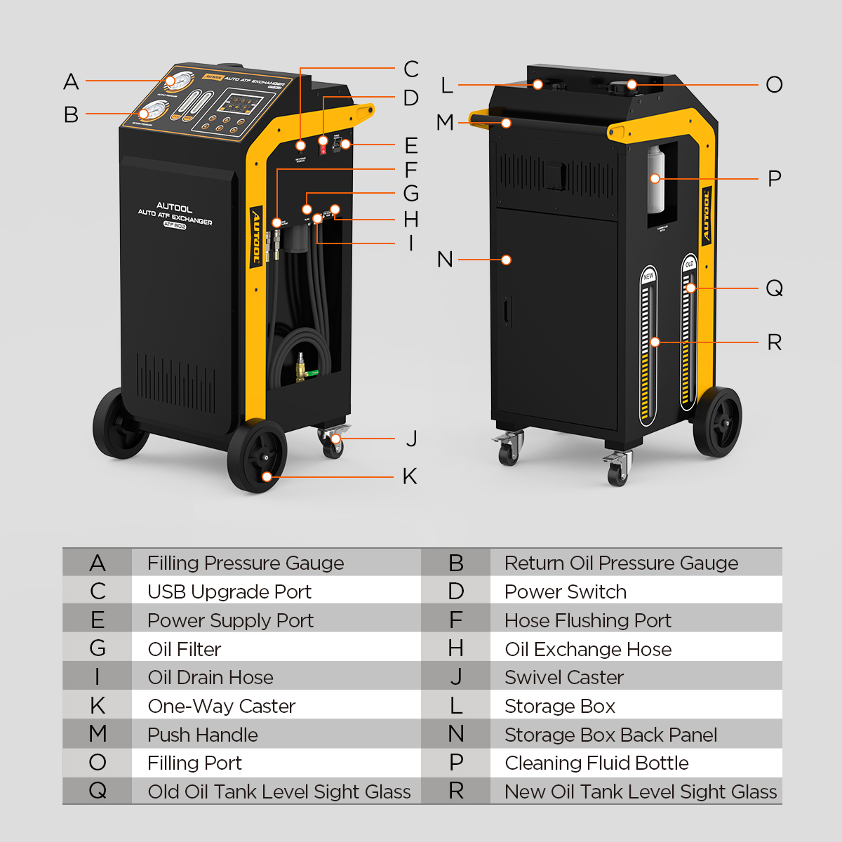
At the front, identify the filling-pressure gauge, return-pressure gauge, old/new fluid sight glasses, five-inch display, direction buttons, Back button, and Confirm button. The screen is the command interface; the gauges and windows remain independent checks that fluid is moving plausibly.
Around the cabinet, locate the USB upgrade port, power switch, AC inlet, hose-flushing ports, oil filter, oil drain hose, two oil-exchange hoses, new-fluid filling port, cleaning-fluid bottle, old-tank and new-tank level windows, handle, storage areas, and casters. Do not assume that two nearby ports are interchangeable—read the exact cabinet labels before attaching a hose.
The separate pumps reduce mixing between the new- and used-fluid circuits, but fluid identity still depends on disciplined storage and cleanup. A dedicated new-fluid path contaminated by the previous job can introduce the wrong chemistry even when both pumps work correctly.
ATF802 step-by-step operating procedure
Step 1: Confirm that the transmission is a suitable exchange candidate
Record the driver’s concern, previous service, known fluid, leaks, warning messages, shift quality, and additives. Scan the transmission and related modules. Inspect accessible fluid, pan evidence, cooler lines, connectors, and external leakage.
Do not proceed until severe slipping, loss of drive, delayed engagement, heavy debris, burnt-fluid symptoms, coolant contamination, active electrical faults, hydraulic problems, and significant leaks have been diagnosed. Fluid exchange is maintenance; it does not repair a worn clutch, blocked cooler, failed solenoid, damaged seal, or contaminated cooling system.
Completion check: The transmission is an appropriate maintenance candidate, and no fault requires repair, sampling, pan inspection, or another service method first.
Step 2: Define the exact ATF and the finish procedure
Use vehicle identification, build data, and the transmission code to choose the exact ATF specification. Do not select fluid by color, odor, a broad “universal” claim, or the product left in the machine. Confirm whether the transmission has a dipstick, standpipe, overflow plug, electronic level routine, or another temperature-dependent procedure.
Write down the planned exchange quantity, target temperature window, engine state, selector state, vehicle attitude, fill hardware, torque, adaptation, and verification drive. Treat any quantity suggested by the ATF802 database as a starting value that must match current vehicle information. A database entry cannot identify a modified transmission, service bulletin, regional fill, or prior repair by itself.
Completion check: The job card contains one verified ATF specification, one controlled exchange plan, and the complete final-level method for the actual transmission.
Step 3: Match the machine, software, and AC supply
Read the ATF802 nameplate and record its serial or hardware information. Confirm that the control panel, two gauges, hose labels, tank layout, software mode, plug, and power inlet match the delivered instructions. The product family includes regional AC configurations, so use only the voltage and frequency marked on the physical unit.
With the machine switch off, inspect the power cable end to end. Verify a grounded outlet with suitable voltage, fuse or breaker protection, and workshop protection for the environment. Do not use an improvised plug adapter, damaged extension, wet outlet, or supply inferred from the appearance of another unit.
Completion check: The delivered ATF802 and its single nameplate-matched power method are positively identified before any switch is turned on.
Step 4: Inspect, empty, seat, and zero the tanks correctly
Inspect the cabinet, wheels, gauges, screen, buttons, exchange hoses, drain hose, flushing ports, filter, fittings, seals, fill port, cleaning bottle, tank windows, cord, switch, and storage panels. Confirm that every cap and hose belongs to the intended circuit.
Empty the used-fluid tank into an approved labelled container before it approaches capacity. Remove incompatible fluid from the new side rather than using a customer’s transmission to purge it. Both internal tanks must sit correctly on their scale platforms, and the machine must remain level and stationary.
Use Electronic Scale Reset only when both tanks are empty, seated correctly, and free from outside contact. Never zero a loaded tank. A false zero corrupts the reference used to coordinate new and used quantities.
Completion check: Both paths are identified and clean, tank capacity is available, scale readings are plausible, and any reset was completed only with empty undisturbed tanks.
Step 5: Load enough exact-specification new ATF
With the power switch off, clean the new-fluid filling area. Add the verified ATF through the intended filling route using clean dedicated equipment, or use New Oil Tank Filling only with the exact external-hose routing described below. Prevent water, dirt, lint, used fluid, cleaner, or another ATF from entering the new side.
Confirm that the screen and physical tank indication respond plausibly. Keep the amount inside the tank’s usable limit and above the programmed exchange quantity with a controlled reserve for the machine path and final adjustment. Do not plan to add fluid while equal-volume exchange is active.
Common mistake: Starting with just enough fluid to equal the programmed number. Hose filling, interruption, and final adjustment can consume reserve; an empty new side can introduce air or stop the operation.
Completion check: The loaded fluid is exact, traceable, uncontaminated, within tank capacity, and sufficient for the controlled job plan.
Step 6: Select adapters and open the approved cooler-line point
Use the vehicle procedure to identify a serviceable point between the transmission and its cooler circuit. Bring the system to the specified safe temperature and pressure condition, clean the area, place containment below it, and release residual pressure only as directed before opening the connection.
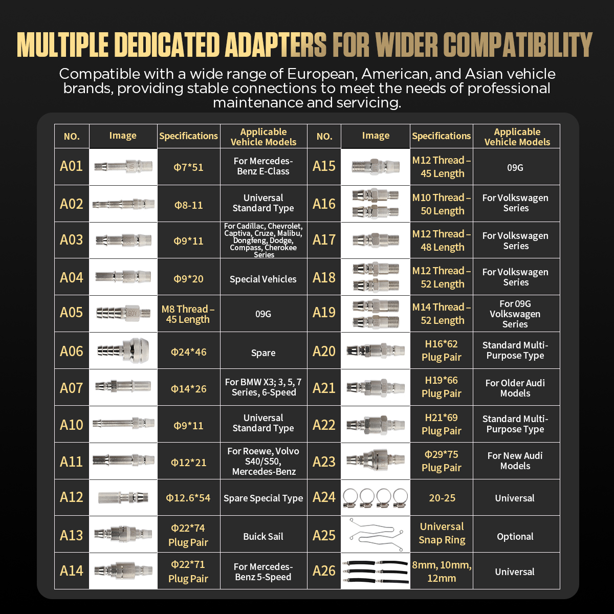
Match the adapter by thread, sealing face, diameter, locking method, and unrestricted flow—not by appearance alone. Some vehicles require a dedicated fitting not supplied in the general assortment. Replace one-time seals, clips, and retainers as specified, and avoid side-loading a rigid or aged cooler line.
Stop: Do not improvise with mismatched threads, stacked adapters, sealant that can enter the circuit, damaged quick connectors, reduced-bore fittings, or a connection point that the vehicle procedure does not approve.
Completion check: Both vehicle ends and both machine connections can form a fully retained, full-flow series circuit with the correct seals.
Step 7: Build and inspect the closed fluid circuit
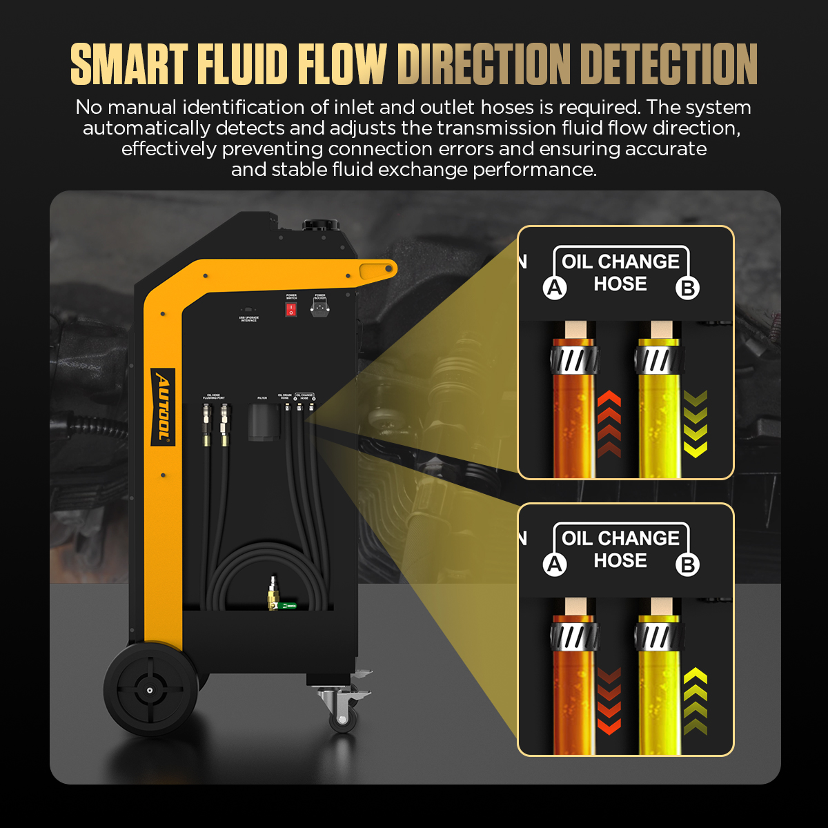
Connect the two ATF802 exchange hoses to the approved ends of the opened vehicle cooler circuit. Automatic direction detection means you do not need to guess supply and return direction before the machine configures flow, but it does not make the physical connection self-checking.
Lock every quick coupling and original retainer, then pull-test each joint by hand. Route both hoses with slack for normal engine movement while keeping them away from heat, sharp edges, wheels, axles, fans, belts, and lift contact. Make sure neither hose is twisted, kinked, pinched, or carrying the weight of an adapter.
Completion check: The vehicle and ATF802 form one closed series circuit, every joint is locked, and the complete route is visible and protected.
Step 8: Apply nameplate power and perform a low-risk leak check
Keep the ATF802 power switch off while connecting the verified AC cable. Secure the cord so it cannot be pulled by vehicle, lift, cabinet, or foot movement. Confirm that both tanks remain undisturbed on their scales.
Start the vehicle only in the state specified by its service procedure. Keep driven wheels stationary unless the exact vehicle procedure requires a different condition and the lift, restraint, ventilation, wheel-clearance, and workshop controls are rated for it. Inspect all cooler-line and machine joints for leakage before switching on the ATF802.
Turn on the machine, allow the screen to initialize, and watch for warnings or implausible values. If the displayed tank quantity, pressure, fluid path, or software state does not match the physical machine, switch off and resolve the discrepancy.
Completion check: The vehicle circuit is leak-free under its approved state, power matches the nameplate, and the machine starts with plausible readings.

Step 9: Choose the operating mode, exchange function and quantity
On first startup, choose Standard Mode for fuller prompts and guidance. Simplified Mode reduces interface detail and is better reserved for an experienced operator who already knows the exact workflow. Mode Selection remains available under Maintenance & Settings.
Select Circulating Oil Exchange for the normal equal-volume service. Choose either Custom Exchange Volume or the vehicle-database path. If using the database, navigate the displayed series, brand, model, and year, then compare the suggested quantity with the transmission code and current service information. Reject any mismatch.
Read the entire prompt before confirmation. The set quantity must not exceed the verified new-fluid amount or the available used-fluid capacity. Do not use a generic multiple of total capacity or an advertised replacement percentage as the target.
Completion check: The screen shows the intended function and a vehicle-validated quantity that fits both tank limits and the written job plan.
Step 10: Prove flow direction and stable operation before committing
With the vehicle in its approved operating state, start the selected function as prompted. Let the ATF802 identify the connected flow direction and establish both paths. Watch the two pressure gauges, screen values, fluid windows, tank indications, hoses, and every connection.
Normal pressure is vehicle-dependent; a gauge is a trend and fault-detection aid, not a universal target. Stop for a sudden rise or drop, stalled flow, severe pulsation, aeration, hose movement, leakage, pump noise, incorrect fluid direction, unstable scale data, or a new/used quantity difference that does not settle under the machine’s control.
Pass condition: Both paths contain fluid, the detected direction produces stable circulation, all connections remain dry, and the displayed quantities agree with the physical tank and window behavior.
Step 11: Run and supervise the equal-volume exchange
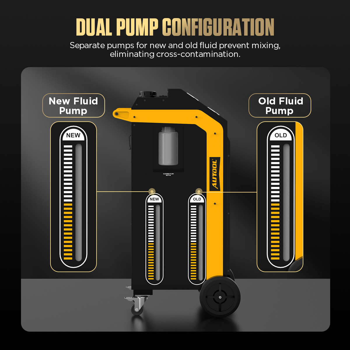
Continue only after the low-risk check passes. The separate new- and used-fluid pumps should move fresh ATF into the circuit while recovering old fluid under the machine’s scale control. Supervise the process continuously; never leave a powered ATF802 unattended.
Do not move, bump, lean on, or roll the cabinet while it is measuring tank weight. Do not add new ATF through the fill port during the active function. Keep the new side above its safe minimum and the used side below capacity. Watch both gauges, both fluid windows, screen values, hose routing, adapter retention, and leaks throughout the exchange.
Operate the selector only through the sequence, dwell, engine state, brake state, and wheel condition approved for that vehicle. Do not force a higher gear, apply throttle, or run raised driven wheels from a generic instruction. Some transmissions require special scan-tool commands or prohibit particular conditions.
Common mistake: Watching only fluid color. Similar color does not prove correct chemistry, complete exchange, correct quantity, correct final level, or acceptable transmission condition.
Completion check: The planned measured quantity is reached with controlled new/used balance, stable pressures and flow, sufficient tank margins, no warning, and no leak.
Step 12: Pause or stop through the screen and review settlement
Use the Confirm control to pause when the interface permits. When an end-warning dialog appears, read whether the selected choice returns to the active function or confirms termination. Do not disconnect power or open a pressurized coupling as the normal way to stop.
End early for any safety or fluid-control concern. At the Settlement page, record the actual new and used amounts. A small machine rating does not excuse a growing imbalance, and a balanced display does not replace the vehicle’s final level check.
Stop: If new and used quantities diverge unexpectedly, isolate the reason before continuing. Check tank seating, cabinet movement, available fluid, waste capacity, aerated or restricted paths, leakage, incorrect function, and machine warnings.
Completion check: The function has ended under control, settlement values are recorded, and the circuit is in a safe state for restoration.
Step 13: Restore the vehicle cooler circuit
Switch off the ATF802 and bring the vehicle circuit to the specified safe pressure and temperature condition. Position containment below the connections. Release each machine coupling carefully, cap the machine hoses immediately, and protect the open vehicle ends from contamination.
Reassemble the original cooler circuit with the required new seals, clips, retainers, and fittings. Support the line naturally and use the specified torque. Clean the area so a fresh leak can be identified. Do not reuse a distorted seal or damaged quick-connector lock merely because it appears to hold while stationary.
Completion check: The original vehicle circuit is fully restored, retained, torqued, clean, and ready for a pressure leak check.
Step 14: Set final level, verify operation, and close the job
Follow the vehicle’s final-level procedure from the beginning. Hold the vehicle at the specified attitude, monitor transmission-fluid temperature with the required method, use the exact engine and selector state, and add or drain only the verified ATF. Do not default to Park, a cold dipstick mark, or a generic engine-running rule.
Run the engine and inspect the restored cooler connection, pan, fill or level point, and every disturbed area. Confirm normal engagement and scan data before a controlled road test. Perform adaptation or relearn only when the vehicle procedure requires it. Recheck for leaks and level under the specified return condition.
Drain the used-fluid tank promptly into a labelled waste container. Empty incompatible remaining new fluid into a clean labelled container. Wipe the machine, inspect the filter and hoses, record fluid lot, quantities, temperatures, codes, repairs, final level, leaks, and test result, then store the cabinet dry with both tanks empty.
Completion check: Fluid level is correct in the required temperature window, the transmission operates as expected, the circuit remains dry, the machine is clean and empty, and the service record is complete.
Use Pipe Self-Flushing to control cross-contamination
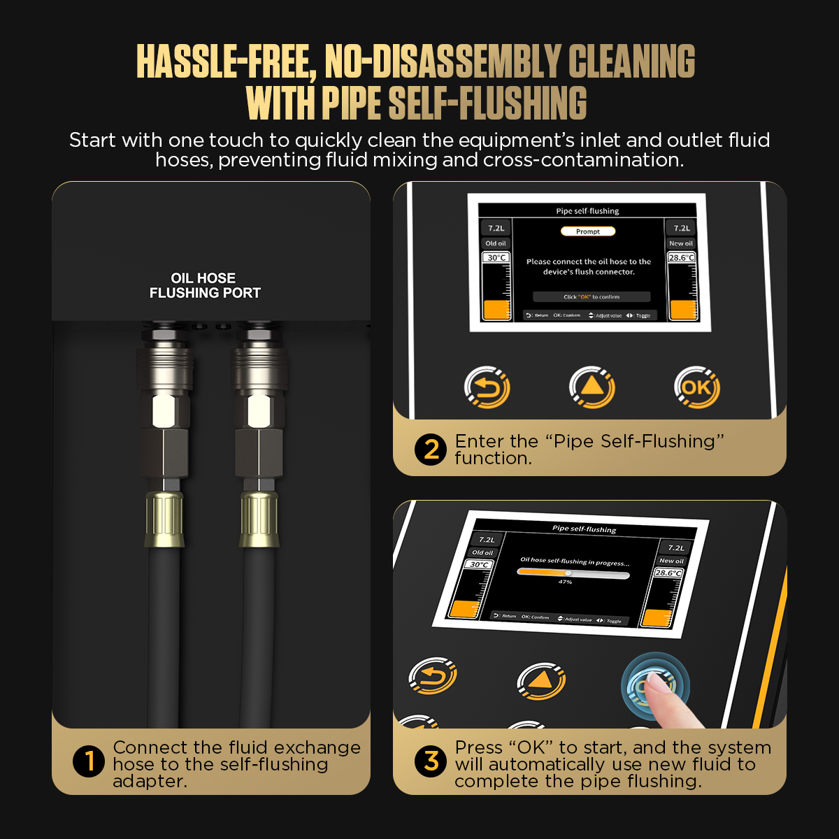
Pipe Self-Flushing cleans the ATF802’s own exchange hoses with new fluid. It is an internal machine utility, not a vehicle flush. Disconnect the machine from the vehicle, connect the two exchange hoses only to the labelled self-flushing ports, confirm compatible new fluid is available, choose Pipe Self-Flushing, read the prompt, and start with the Confirm control.
Collect or account for the displaced fluid as the machine instructions require. After completion, cap the hoses and ports to prevent dirt entry. This process helps manage residue in the machine paths, but it does not make mixed fluids compatible or clean a contaminated new tank automatically.
Use the recovery, filling, and tank functions without cross-routing
The utility menus move fluid through different paths. Verify the exact hose routing and engine state before pressing Confirm.
| Function | Intended task | Critical control |
|---|---|---|
| Old Oil Recovery | Recover a programmed amount from the connected vehicle | Keep within used-tank capacity; a zero setting requires manual stop |
| New Oil Filling | Add a programmed amount to the connected transmission | Keep the engine off; quantity cannot exceed available new fluid |
| New Oil Tank Emptying | Drain the machine’s new-fluid tank to an external container | Use the specified transparent hose; leave the other exchange hose unconnected |
| Old Oil Tank Emptying | Drain the machine’s used-fluid tank to an external container | Connect the drain hose, open its manual valve, and leave exchange hoses unconnected |
| New Oil Tank Filling | Draw new fluid from an external container into the machine tank | Use the cleaning-fluid suction route and stay within new-tank capacity |
Never select a vehicle service function when the vehicle circuit is not connected. Conversely, do not leave the vehicle connected while routing hoses for an internal tank-emptying or pipe-self-flushing task.
Treat chemical circulating flushing as an optional specialist procedure
Circulating Flushing is separate from the normal correct-fluid exchange. A generic cleaner can affect friction materials, seals, coatings, fluid chemistry, and final ATF compatibility. Do not assume that a cleaning bottle, menu, or timer makes the chemistry suitable.
Use a chemical only when the transmission manufacturer, chemical supplier, and delivered ATF802 instructions all approve the exact product, dose, temperature, operating state, recovery method, and final exchange. Otherwise omit chemical circulation and perform the approved ATF service. No fixed duration or selector routine is universal.
Three completion gates before releasing the vehicle
Gate 1: Fluid control
The exact ATF is documented. Actual new and used quantities are recorded. Final level is correct inside the specified temperature window. No wrong-fluid, cross-contamination, aeration, overfill, or underfill concern remains.
Gate 2: Mechanical and hydraulic integrity
Every original cooler connection is restored with correct sealing and retention. Hoses and fittings are routed normally. The vehicle and ATF802 show no leak, abnormal pressure, blocked flow, damaged line, or loose component.
Gate 3: Vehicle and machine verification
The transmission engages and operates as expected, relevant data and codes are acceptable, and any required adaptation is complete. The ATF802 used tank is drained, incompatible new fluid is removed, scale platforms are clean, hoses are capped, and the service record is complete.
Troubleshooting ATF802 operation
The machine will not start the selected exchange
Confirm the power switch, nameplate supply, fuse or circuit protection, screen state, selected function, sufficient new fluid, available used-tank capacity, tank seating, scale readings, and completed prompt. If a value is implausible, do not bypass it—correct the cause or obtain service support.
Flow direction is detected but fluid movement is unstable
Stop the function. Check for a kinked hose, incomplete coupling, incorrect or restricted adapter, closed vehicle path, low new-fluid level, full used tank, aeration, filter restriction, pump fault, or unsupported vehicle operating state. Do not increase throttle to force flow.
New and used quantities do not remain controlled
Pause and inspect for cabinet movement, an object touching a tank, a loaded tank that was incorrectly zeroed, leakage, air, restricted flow, low new fluid, full used capacity, or the wrong function. Do not compensate by pouring fluid into the active tank.
Pressure changes sharply
Stop before a hose or seal is overloaded. Compare both gauges, screen behavior, fluid windows, vehicle state, and connection routing. A sharp change can indicate a restriction, selector-related circuit change, cooler issue, adapter problem, aeration, or stalled pump; diagnose instead of applying a universal pressure target.
New Oil Filling does not proceed
Verify that the engine is off, the selected quantity does not exceed new-fluid availability, the vehicle connection is correct, and the prompt has been confirmed. Do not start the engine to “help” this function.
Maintain the ATF802 for repeatable measurements
After each job, drain used fluid promptly, remove incompatible new fluid, clean spills, cap every port, inspect hoses and seals, and keep the scale platforms free from debris or side contact. Store the machine upright in a dry, ventilated area with both tanks empty and the cord protected.
Inspect the filter, electrical cable, fittings, gauges, wheels, cabinet, and chemical-contact areas regularly. Replace damaged parts before another vehicle is connected. The ATF802 instructions recommend replacing the filter after 50 transmission-fluid services; use Filter Reset only after the filter has actually been replaced.
Electronic Scale Reset requires both tanks empty and correctly seated. Factory Settings is not a routine cure for a fault because it also restores the scale’s factory calibration state. Record software and hardware information from About the Machine before service or update work.
ATF802 FAQ
Does automatic direction detection mean either hose connection is always safe?
No. It helps the machine configure flow direction after a correct sealed series connection is built. It cannot approve an adapter, repair a restricted cooler line, prevent leakage, or make an unsupported service point acceptable.
Should I trust the vehicle database quantity without checking?
No. Match the transmission code, build, service information, and actual procedure. Database selection is a convenience, not authority for fluid chemistry, capacity, final level, selector state, or modifications.
How much ATF should I exchange?
Use the documented vehicle plan, not a universal multiplier or percentage. Stay within both machine tank limits, maintain a reserve, record actual settlement values, and finish with the vehicle-specific temperature-dependent level check.
Can I add ATF while Circulating Oil Exchange is running?
No. Stop and complete the function before adding fluid. Adding to the measured tank during active equal-volume control can corrupt the balance.
Should the driven wheels be raised and accelerated through the gears?
Only when the exact vehicle procedure requires a defined wheel or driveline condition and the workshop equipment and restraints are rated for it. The safe default is stationary driven wheels; never force speed or gear changes from a generic instruction.
Is Circulating Flushing required before every exchange?
No. Chemical flushing requires explicit compatibility and process approval. Pipe Self-Flushing, by contrast, is an internal machine-hose cleaning function that can help prevent cross-contamination when routed exactly to the labelled ports.
Can New Oil Filling run with the engine on?
No. The ATF802 instructions require the engine to remain off during New Oil Filling. Select the correct programmed amount and verify final level later with the vehicle’s complete procedure.
The reliable ATF802 workflow
Start with diagnosis and exact vehicle data. Prepare clean, correctly seated machine tanks on a level stationary cabinet. Match nameplate power, select full-flow adapters, build a sealed cooler-line series circuit, and use Standard Mode until the prompts are familiar. Validate the exchange quantity, prove stable flow, then supervise both pumps, scales, gauges, windows, hoses, and tank margins until the planned amount is complete.
Finish the job outside the machine menu: restore the original cooler circuit, set fluid level at the specified temperature, verify operation and leaks, document the result, drain waste, segregate remaining fluid, and leave the ATF802 clean, empty, capped, and ready for a known fluid on the next vehicle.


Comments 0
Questions, fixes, and real-world diagnostic notes from readers.
Be the first to share a diagnostic result or ask a follow-up question.