
Audi 2.0T FSI Carbon Cleaning: Access, Debris Control, and Reassembly

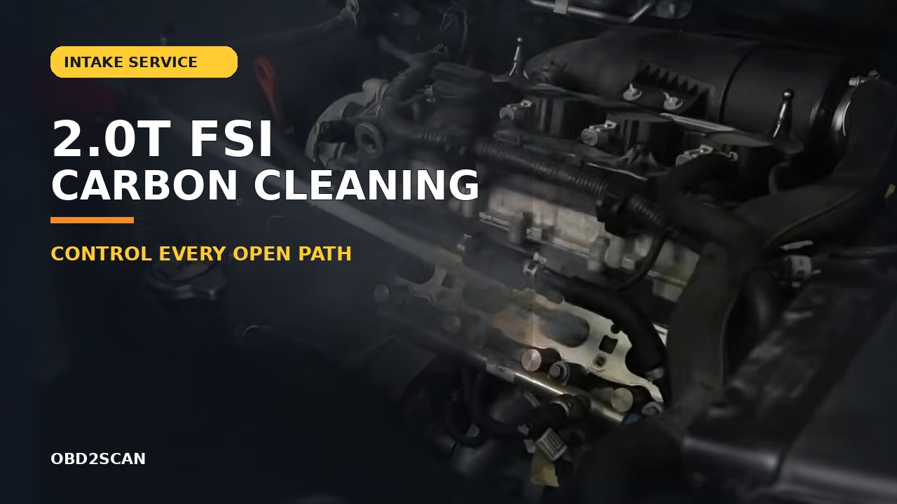
This 2011 Audi 2.0T FSI project remains valuable because it records the entire messy middle of a manifold-off carbon clean: the fuel and coolant connections, hidden plugs, support bracket, injector seals, cleaning, priming and first start. Its famous ‘$20’ label does not describe a complete current budget, and several of its shortcuts should be treated as history rather than instructions.
Bottom line: a complete manifold-off clean crosses fuel, coolant, electrical and intake boundaries before any carbon is touched. Its strongest lessons are to inventory every connection, protect every open path, budget new one-time or disturbed seals from current vehicle information, and document a genuine matched before/after instead of relying on representative photos.
Updated August 27, 2026.
In this project
Why the full scope matters
The available sequence was reconstructed after the work and did not preserve every specification. Current vehicle information therefore controls turbo, intake-manifold, high-pressure-fuel-pump and injector procedures, while the recorded sequence is best used to understand scope and likely access problems.
A short instruction such as ‘remove the intake manifold’ hides several separate system boundaries. The recorded sequence makes those boundaries visible, but it is not current service information. Fuel pressure, connector handling, seal replacement, fastener specifications and coolant restoration must come from the procedure for the exact VIN, engine code and market.
Project at a glance
| Item | What the 2011 project recorded |
|---|---|
| Engine family | Audi/VW 2.0T FSI direct-injection application; exact vehicle details were not consistently reported |
| Headline cost | $15–$30 for the cleaning materials remembered at the time, not a complete 2026 job cost |
| Main access systems | PCV, fuel line and HPFP area, coolant tube, throttle body, manifold support and electrical connectors |
| Main evidence weakness | The published photos were after-cleaning views; some ‘before’ illustrations came from other people |
| Result | Reassembled, primed and started; an initially uneven idle settled |
The real job started before any carbon was cleaned
The remembered tool list included Torx bits, extensions, pliers, towels, coolant and cleaner. More important than the brand names was the access plan. The engine had to be cold and safe to service; fuel-system pressure and electrical energy had to be handled by the applicable procedure; removed lines and openings needed caps; and every connector needed a route back home.
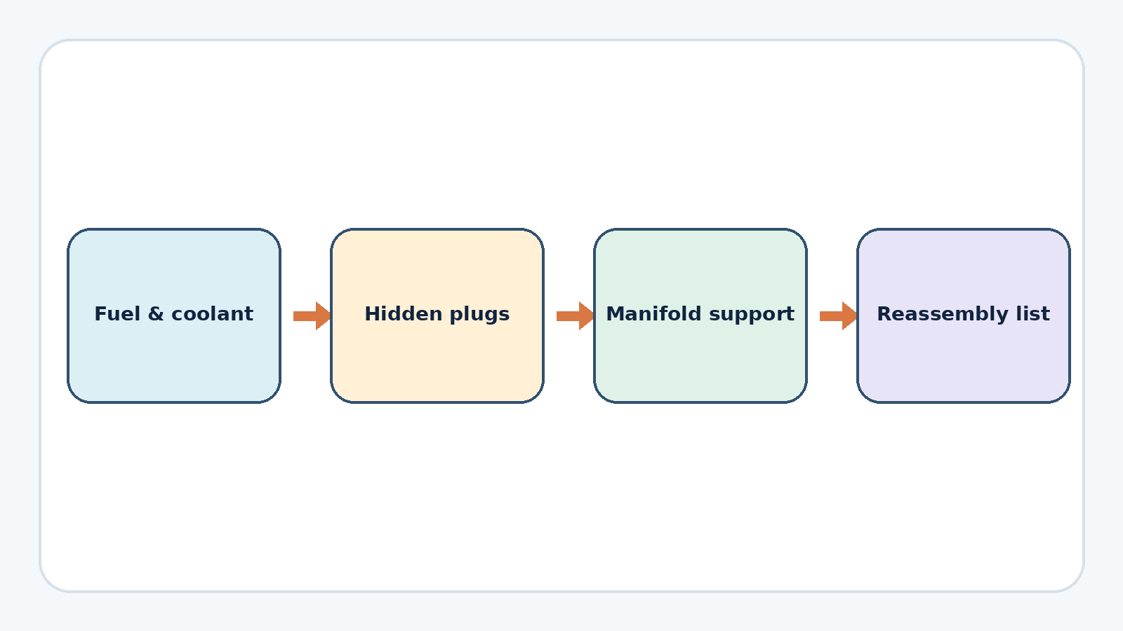
The sequence passes through the PCV assembly, fuel line and high-pressure-pump area, coolant tube, wiring and throttle body before the manifold can come free. This is why the headline price is misleading for planning. A current budget should include the correct seals, gaskets, coolant, spill-control supplies, protective caps, any required one-time fasteners and the tools needed to release fittings without damage.
Hidden connections drove the removal pace
Several easy-to-miss retainers and connections control the removal pace: connectors under or behind the manifold, the dipstick tube, a support bracket, coolant plumbing and injector O-rings that could stick or fall. The useful pattern was stop, identify what still retained the assembly, and release it deliberately. Pulling harder would not make an undiscovered bracket disappear.
A good modern version of the project would use a connector and fastener board. Photograph each layer before removal, number the connectors, bag fasteners by component, and mark the open ports immediately. If an injector lifts with the rail or manifold, stop and follow the correct injector resealing and installation procedure instead of pressing an old seal back into service because it looks intact.
The cleaning method needs a modern safety boundary
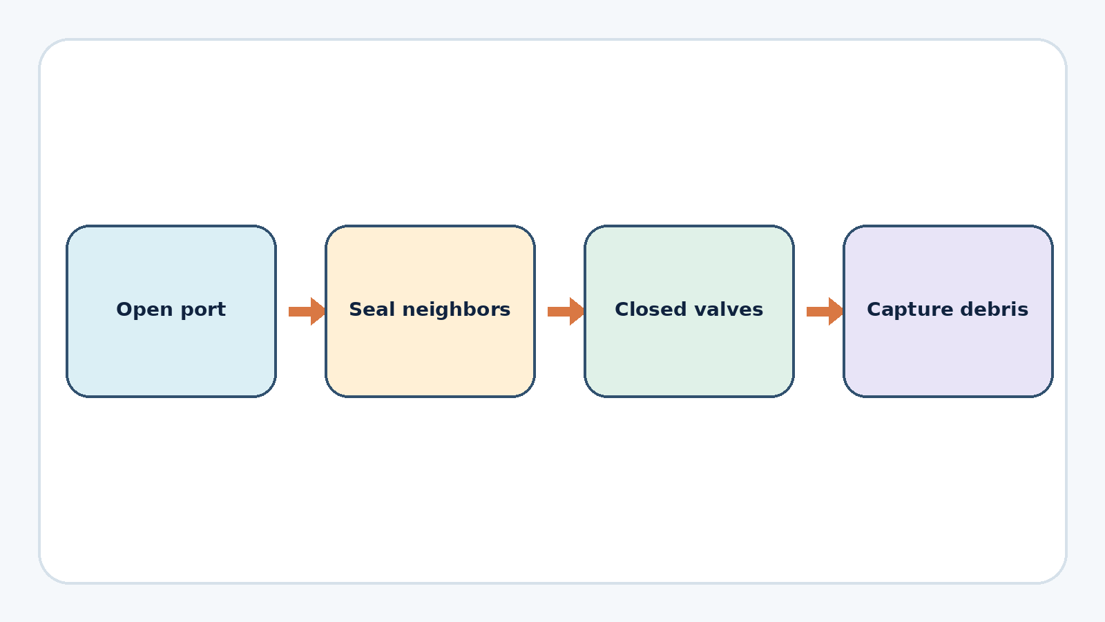
Deposits were soaked, loosened gently and removed. A wire brush adds surface-damage risk, and any loosened material entering the engine is an unacceptable loss of control. Closed intake valves, sealed neighboring ports, continuous capture and a final inspection are the minimum logic of a controlled job.
Do not rotate the engine with loose material sitting in an exposed port. Do not assume a liquid cleaner or soft carbon is harmless inside a cylinder. If valve position cannot be proved, if debris cannot be removed, or if a valve or port is scratched, stop and escalate the inspection. The exact safe method depends on the current service information and the cleaning equipment used.
A successful restart cannot validate debris ingestion as a technique. The rule is simple: nothing enters an open intake path unless the vehicle procedure explicitly permits it, and the port must pass a lighted inspection before reassembly.
The photo record was not a true before-and-after
The available photos show the ports after cleaning; the earlier-condition examples are not matched images of the same ports. They therefore cannot support a visual claim about the amount of change on this engine.
This is a useful lesson for any repair journal. Take each port before cleaning, keep the camera angle, distance and light consistent, and repeat the same view after the final inspection. Label the cylinder and never substitute a representative engine. If the first photo was missed, say so; a truthful after-only record is more useful than a persuasive but mismatched comparison.
Reassembly and the first start
The manifold had to align with its studs and support points without trapping wires or disturbing seals. Coolant was restored, the fuel system was primed, and the vehicle was started. The first few moments were uneven before the idle recovered. That immediate result does not make every rough first start after this job normal.
A safer pass/fail sequence is to inspect all connections before energy is restored, prime only as the vehicle procedure directs, watch immediately for fuel and coolant leakage, scan for faults, and shut down for persistent misfire, abnormal mechanical noise, warning messages, fluid loss or odor. A stable idle is only the first check; a heat cycle, cooled-down level check and fault rescan complete the immediate verification.
What to carry into your own project
- Use the sequence as a map of access layers, not as the current specification for your car.
- Ignore the historical $20 headline when budgeting seals, fluids, damaged connectors and correct tools.
- Build debris containment and true before/after photography into the plan before the manifold comes off.
- Treat a disturbed injector or damaged seal as a separate controlled task.
- Verify with leak checks, a scan, stable operation and a cooled-down recheck—not only a successful first start.
If the original complaint was rough idle or misfire, begin with the rough-idle evidence path so cleaning is tied to a reason. If fuel-system access, open-port control or recovery from a broken fitting exceeds your setup, the DIY-or-shop checklist gives a more useful decision than the historical low headline price.






Comments 0
Questions, fixes, and real-world diagnostic notes from readers.
Be the first to share a diagnostic result or ask a follow-up question.