
Ford F-150 Says Trailer Disconnected on Bumps? Build a Connector Event Log

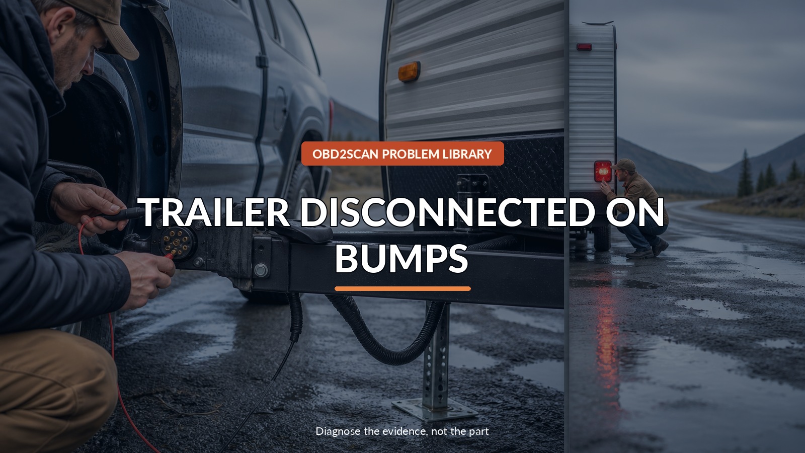
Trailer Disconnected On Bumps
If an F-150 says Trailer Disconnected while the trailer is still attached, first prove whether required trailer lamps and brakes still work. If electric brakes, turn/stop lamps, or required running lamps are unavailable or intermittent, pull over safely and stop towing. A bump-triggered message is an electrical event to capture across both truck and trailer—not immediate proof of a bad Ford module.
Once the correct conventional circuit is identified, a load-aware circuit tester can help separate an open, weak ground, supply loss, or connector problem. The MRCARTOOL B550 circuit analyzer is one multi-function route. Its powered output must never be used on an unknown module, network, brake-control, sensor, or safety circuit, and it cannot certify that a trailer is safe to tow.
Use a field log because intermittent trailer faults often disappear as soon as the rig reaches the shop. The road, weather, trailer, message, and failed function all belong on the same line.
Quick answer: Stop towing if required lights or brakes are lost, then use the bump event to separate truck, connector, adapter, and trailer circuits under load.
In this guide
Stop if the safety functions are gone
Signal, brake, and marker requirements vary by trailer and jurisdiction, but a driver should not continue when the combination cannot communicate or stop as designed. Choose a safe parking area, use hazard protection, and chock as appropriate before inspecting between truck and trailer.
Do not crawl between vehicles on a grade or touch damaged wiring that is hot, smoking, or shorting. Disconnect shore power, breakaway battery, or other auxiliary sources only by the trailer maker’s procedure. A seven-way connector may have live charge and auxiliary feeds even with the truck switched off.
Test the breakaway system only according to the trailer manufacturer’s instructions; it is not a parking brake and should not be used as a convenient load switch.
Write down the exact bump event
Have a passenger record, or use a hands-free log after stopping. Note:
- F-150 year, VIN, tow package, controller, and software state;
- trailer type, connector, brake count, auxiliary battery, and adapters;
- exact message wording and chime;
- speed, road surface, steering/braking input, and which wheel hit the bump;
- rain, wash, salt, dust, or recent connector handling;
- brake-controller display/output and lamp behavior; and
- whether the message self-cleared or required a key cycle.
Try not to unplug and reseat the connector before documenting its fit. Reseating can scrape corrosion, tighten a marginal contact, and erase the original condition.
Divide truck side from trailer side
Begin with a complete module scan and save current/history codes. Then inspect the truck socket, plug, adapter, strain relief, junction boxes, trailer harness, axle drops, grounds, and breakaway wiring. Look for looseness, spread or pushed-back terminals, green corrosion, water, heat, bent lids, chafing, poor crimping, and a cable that becomes taut during turns.
A known-good trailer or a dedicated load/simulator can be useful if it is compatible with Ford’s sensing strategy. Likewise, the suspect trailer on another suitable tow vehicle can provide evidence. Neither swap is conclusive if adapters, brake-controller settings, grounds, or vehicle detection logic differ.
Record a two-column result:
| Truck-side evidence | Trailer-side evidence |
|---|---|
| socket retention, supply, ground, codes, known load | plug tension, chassis ground, junctions, brake magnets, cable movement |
The side that reproduces the event earns deeper testing. Do not replace both sides to avoid choosing.
Inspect retention before measuring voltage
Connector contact pressure matters. A terminal can show battery voltage while resting and open when vibration moves the plug. Inspect terminal drag/tension only with approved test pins or gauges; forcing a meter probe into the socket can spread the terminal and create the fault you are chasing.
Support the cable so its weight does not lever the plug. Confirm the socket door or latch actually retains the connector. Inspect adapters especially closely—each extra interface adds another contact and another strain point.
Check grounds mechanically and electrically. Trailer frames can have paint, rust, moving couplers, and multiple bolted sections that make a visual ground strap look better than it performs.
Load the circuit instead of trusting open-circuit voltage
Use the Ford wiring diagram and trailer standard to identify each pin. Measure open-circuit voltage for orientation, then test voltage drop under the circuit’s real safe load. Compare the ground drop and supply drop while the affected lamp or brake load operates. A tiny test light may not reveal a connection that fails with several brake magnets energized.
For intermittent work, attach rated leads securely, route them away from tires and exhaust, and record minimum/maximum or a graph while the connector is moved gently in the bay. Do not drive with loose test leads.
Never inject power to “see what happens” unless the conductor, load, current limit, module isolation, and trailer-maker procedure are all proven. Modern tow modules monitor their outputs and can be damaged or confused by backfeeding.
Use Ford’s SSM only inside its scope
Ford SSM 49708 addresses a trailer-disconnected concern on specified 2018–2020 F-150 and related vehicles and points technicians to a Trailer Module procedure. It is not a universal instruction for every F-150 year, every message, or every trailer.
Check exact model, year, equipment, symptom, DTCs, and current Ford service information. If the vehicle falls outside the SSM, use its own manual and wiring. If the trailer-side fault is already proven, the presence of a Ford note does not move the fault back into the truck.
Module replacement or programming requires stable voltage, correct configuration, and a supported service system. Do not use a generic code clear as a module test.
Verify with the same trailer and route
Repair terminals with approved parts and crimp/seal methods, restore strain relief, clean and protect only as Ford/trailer documentation specifies, and secure the harness through full hitch and suspension movement. Confirm all lamps, charge feed, controller output, and breakaway system by their own procedures.
Then repeat a controlled road test with the same trailer, load, connector/adapter, controller setting, weather if relevant, and representative bumps. Monitor without distracting the driver. Re-scan the truck and inspect the connector for heat.
The fault is resolved when the original trigger no longer causes a disconnect, required functions remain stable under load, no related DTC returns, and the repair record says whether truck, trailer, adapter, or connection caused the event.







Comments 0
Questions, fixes, and real-world diagnostic notes from readers.
Be the first to share a diagnostic result or ask a follow-up question.