
BMW F02 740 MIL: Oxygen-Sensor Heater Open Circuit Confirmed, Sensor Replaced

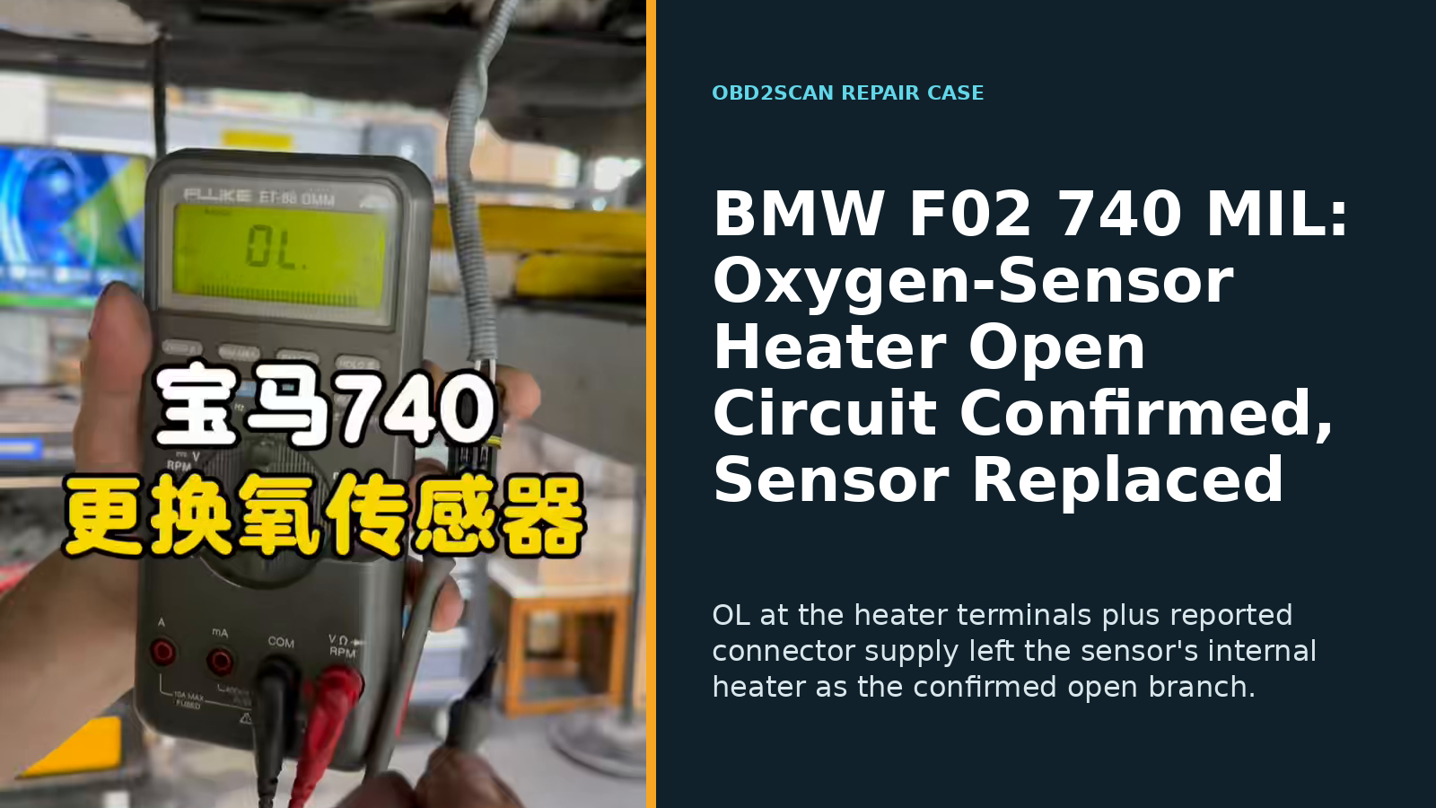
A BMW F02 740 of unreported year, engine and mileage arrived with the malfunction indicator lamp on and an oxygen-sensor heater open-circuit fault. The heater circuit had two live candidates—the sensor element or the vehicle wiring/control side—and an OL resistance reading at the removed sensor plus reported supply at the connector separated them. The affected sensor was replaced and DME fault/adaptation memory was cleared, but an after-repair rescan, heater-current result and cold-start feedback check were not reported.
Case at a glance
| Item | This BMW |
|---|---|
| Vehicle | BMW 740, F02; year not reported |
| Engine / mileage | Not reported |
| Complaint | MIL on; oxygen-sensor heater open-circuit fault |
| Decisive tests | OL at the removed sensor heater terminals; vehicle-side heater supply reported present |
| Confirmed fault | Open internal heater element in the oxygen sensor |
| Repair | Affected oxygen sensor replaced |
| Restoration | DME fault memory and fuel-mixture adaptations cleared for relearning |
| Verification | Staged pending: no final rescan, current check, readiness result or cold-start feedback result reported |
An open heater code has two branches
The fault message pointed to a circuit, not automatically to a part. An internal heater element can open, but so can a wire or connector; the DME supply/control path can also fail. Replacing a sensor before separating those branches would turn diagnosis into a guess.
The source does not give the exact DTC, sensor position, engine or connector pinout. That prevents this article from naming a “front” or “rear” sensor or publishing terminal numbers. The workshop’s logic remains usable because it is defined by the test points: first the disconnected sensor, then the vehicle connector.
Infinite resistance confirmed the sensor-side open
With the sensor disconnected, the technician placed the meter across the identified heater terminals. The display showed OL, the meter’s over-limit/open indication. Within the correct pin selection and meter setup, that result means there was no continuous path through the sensor’s heater element.
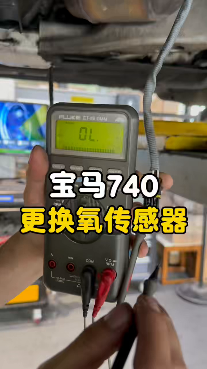
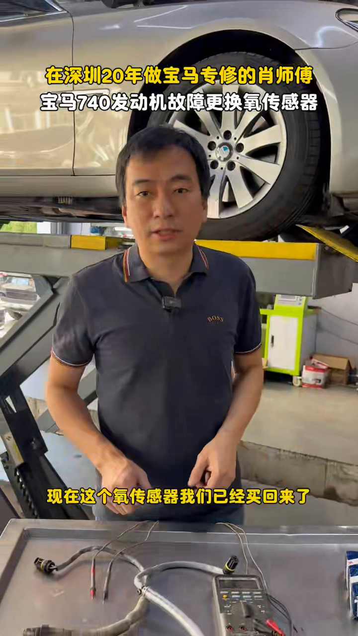
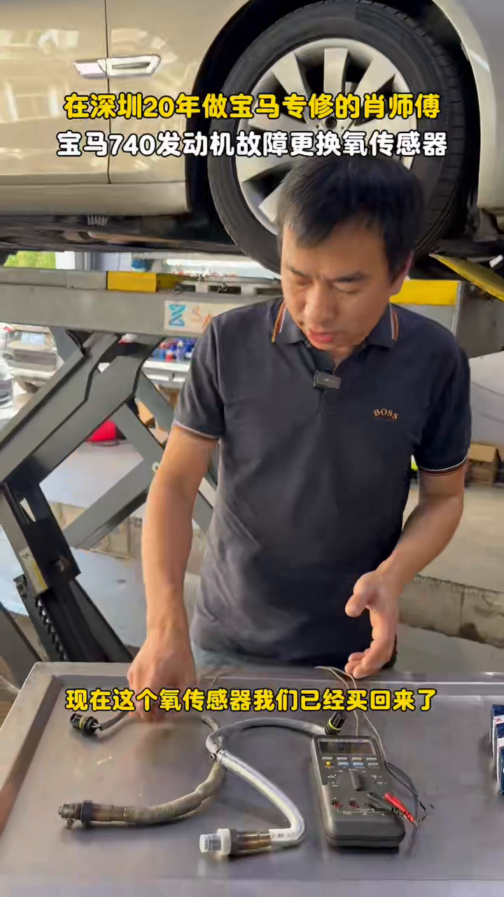
No numeric resistance is reported because an open circuit does not produce a finite value. More importantly, the expected heater resistance and test temperature are absent. A different reading must be judged against service data, not against a number invented from this case.
Supply verification kept the harness/DME branch separate
An open sensor reading confirms the component only if the probes are on the correct heater terminals; it does not show that the car can operate the heater. The source separately reports checking the vehicle connector and finding heater supply present. That result kept an upstream open-supply fault from being folded into the sensor diagnosis.
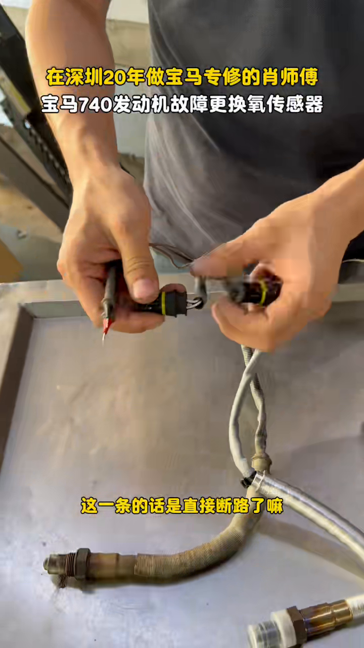
For this resistance and supply task, a meter with appropriate circuit capability such as the AUTOOL DM303 can display the electrical result when used with the correct application data. It cannot choose the correct pins, identify which oxygen sensor the DTC refers to, or prove exhaust feedback after replacement.
The exact supply voltage, command state, ground-side control behavior and pinout are not reported. “Supply verified” is therefore retained as a case fact without turning it into a generic F02 wiring diagram.
Replacement and DME restoration
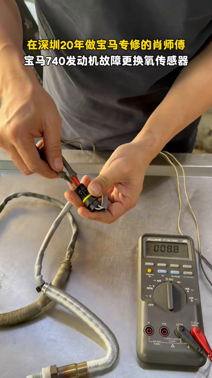
With the internal heater open and connector supply reported present, the source records replacing the affected oxygen sensor. The wiring must not be twisted during removal or installation, and the exact socket, routing clips, tightening specification and anti-seize policy depend on the sensor and BMW service information. None of those values is supplied here.
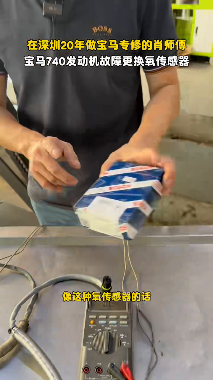
After replacement, the source reports clearing DME fault memory and fuel-mixture adaptations so the controller could relearn with the new input. That is restoration work, not verification. Clearing memory can erase a symptom from the screen without proving that the heater now draws current or reaches closed-loop operation.
The missing post-repair result keeps the case staged
No after-repair scan, heater-current observation, readiness monitor, closed-loop transition or cold-start result is documented. The repair package therefore remains at staged_pending verification strength. The confirmed diagnosis and reported replacement are useful, but the article does not label the emissions function fully verified.
The next closeout should repeat the original electrical/scan touchpoint after a cold start: verify the heater circuit does not reset its fault, observe appropriate operation with application data, and confirm no wiring is touching the exhaust. Readiness status may require the applicable drive cycle; that result cannot be inferred from a cleared code.
How to use this evidence on another BMW
Preserve the exact DTC and sensor position, then separate the circuit at the connector. Measure the sensor heater only across verified heater pins, and check vehicle-side supply/control under the conditions specified for that build. OL at the correct sensor pins plus a working supply branch supports an internal heater failure.
Do not copy the sensor choice, pinout or expected value from “F02 740” alone. Engine, emissions package and sensor position change the circuit, and a code without the two-branch test can still describe wiring or control rather than a failed sensor.










Comments 0
Questions, fixes, and real-world diagnostic notes from readers.
Be the first to share a diagnostic result or ask a follow-up question.