
How to Use the MRCARTOOL B550 Automotive Circuit Tester

The MRCARTOOL B550 automotive circuit tester combines passive measurement with three active functions: a current-limited 0–5 V output, controlled battery-power activation and a basic frequency/scope display. That range is useful only when each mode is treated as a different tool. Start with the vehicle diagram and passive measurement; move to an output mode only after the exact pin, load, polarity and permitted limit are known.
Quick answer: With ignition off and the engine stopped, inspect the B550 and connect red to battery positive and black to battery negative. Use the navigation keys to select VDC, resistance or diode/continuity in Multimeter mode; use OK to start or stop waveform refresh in Oscilloscope mode. The 0–5 V supply changes in 0.5 V steps and is limited below 100 mA, so reserve it for an identified low-current signal simulation. For an approved standalone load, choose Moment activation first, set the breaker from 1–18 A no higher than the component specification and release immediately if current, sound or behavior is abnormal. Never output voltage into an ECU, SRS, network, sensor-supply, protected or unknown circuit.
In this guide
Prepare the circuit and tool
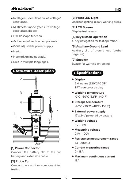
Keep the exact MRCARTOOL B550 manual available at the workbench. It identifies the battery power connector, probe tip, front light, LCD, six navigation keys, auxiliary ground lead and speaker. The specification table gives 12/24 V external battery power and a 9–30 V working range, 0.1–100 V measurement, 1 Ω–200 kΩ resistance range and 0–18 A current range. Those ratings do not override the vehicle maker’s test limits or authorize use on EV traction voltage, mains voltage or ignition secondary.
Wear suitable eye protection, ventilate the area, chock the wheels, select Park or Neutral and apply the parking brake. Keep the probe and cable away from fans, belts, exhaust and hot parts. The manual says not to connect or disconnect test equipment with ignition on or the engine running. Hybrid/EV high-voltage, restraint, pyrotechnic and ignition-secondary systems require dedicated isolation and test equipment and are outside this procedure.
An output mode changes the circuit. The multimeter and scope observe a suitable signal; the 0–5 V and Component Activation modes drive it. Never select an active mode merely to see what happens. Unplanned voltage can damage a controller, corrupt a network, deploy a restraint, move an actuator or overheat wiring.
1. Define the expected result
From the correct wiring diagram, record the circuit name, connector and pin, expected voltage, resistance or frequency, reference ground and required key state. Decide whether the circuit must be energized, disconnected or asleep. Back-probe only where the repair procedure permits it. Avoid piercing insulation because the puncture can admit moisture; if a manufacturer procedure requires piercing, seal the wire by the approved repair method.
Inspect the case, probe tip, insulation, battery clamps, auxiliary ground and cable. Do not use a tool with a loose probe, cut insulation, overheated connector, contaminated clamp or damaged screen. Confirm the battery is not frozen, swollen or leaking. Identify battery polarity from reliable markings and vehicle information rather than cable color alone.
Connect and verify startup
2. Attach the battery clamps
With ignition off and the engine stopped, connect the red clamp to battery positive and the black clamp to battery negative. Make secure contact without allowing a clamp or exposed probe to touch bodywork accidentally. The B550 should start automatically and illuminate the front work area. If the display is abnormal, polarity is uncertain, a clamp arcs excessively or the cable warms, disconnect and correct the setup before testing.
3. Learn the six keys while the probe is clear
Left and Right move between fields or modes; Up and Down navigate or adjust an output value; OK confirms and ESC exits. Their exact action changes with the active screen, so read the label before pressing. Keep the probe off the vehicle while exploring menus. Open Settings only to confirm sound, language, firmware-update and About items; do not begin an update during a vehicle test or with an unstable computer connection.
Use Multimeter mode first
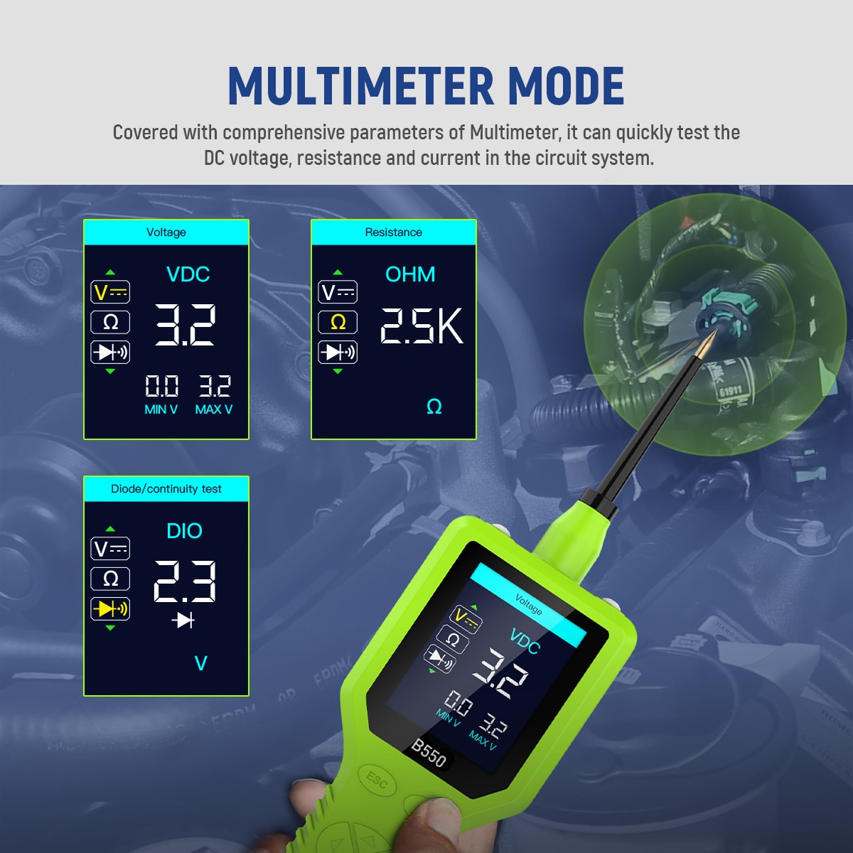
4. Measure DC voltage passively
Enter Multimeter mode and use Up/Down to choose VDC. Connect the auxiliary ground clip to the specified negative reference, then touch the probe to the identified test point. Do not enter either output mode. Compare the displayed value and min/max fields with the service-information expectation under the same key and load condition. A correct open-circuit voltage does not prove the wire can carry current; perform the specified loaded voltage-drop test when required.
5. Measure resistance or continuity de-energized
Turn off and isolate external power as the vehicle procedure requires. Select OHM, connect the auxiliary ground to one side of the conductor or component and place the probe on the other. The manual gives a 1 Ω–200 kΩ range and shows OL above range. Isolate parallel paths when necessary: a low reading through another module can look like good continuity even when the intended wire is open. Continuity is not a load test.
6. Check a diode only in the correct orientation
Select DIO with the component safely isolated. Connect the auxiliary ground lead to one side and the probe to the other, then note the displayed junction voltage and polarity indication. Reverse the connection only if the component and vehicle procedure permit it. A reading in both directions can be affected by parallel circuitry, so remove or isolate the diode when the service method requires a standalone test.
Use Oscilloscope and Hertz modes
7. Observe a suitable low-voltage waveform
Select Oscilloscope, connect the auxiliary ground to the specified reference and the probe to the signal pin. Press OK to start or stop waveform refresh. Use Up/Down on the DIV field to adjust the voltage-per-grid value; the manual states a 1–49 V test range. Read minimum voltage, maximum voltage, frequency and duty cycle together. Change one display parameter at a time and preserve the original setting.
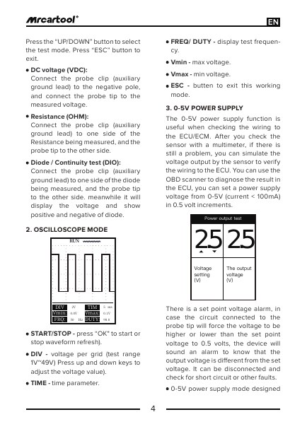
The built-in scope is a quick trend display, not an isolated laboratory oscilloscope. Do not connect it to ignition secondary, mains or EV high voltage, and do not assume it can capture every fast transient. If the vehicle procedure specifies bandwidth, attenuation, differential inputs or an isolation category the B550 does not document, use the specified instrument instead.
8. Read frequency and duty cycle
Use Hertz mode for a suitable AC or square-wave signal. The interface displays frequency and duty cycle. Confirm the signal’s expected amplitude and reference before contact, then compare at the operating condition named in service information. A plausible frequency alone does not prove correct amplitude, shape or loading, so return to the scope or a specified oscilloscope when those details matter.
Use the 0–5 V output only for an identified signal
9. Prove the wiring before simulation
The manual positions this mode as a low-current sensor-signal simulation after the sensor and wiring have already been checked. Before using it, identify the ECU signal pin, verify the expected 0–5 V range and confirm that the line is not a 5 V reference, power feed, ground, network, restraint or actuator driver. Use an appropriate scan tool to monitor the receiving module’s data while a qualified technician controls the output.
10. Start at the safest specified value
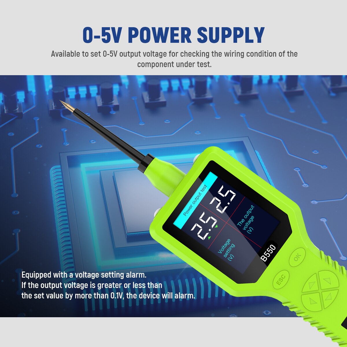
Enter 0–5 V Power Supply and set the exact starting value required by the diagnostic procedure. Up/Down adjusts in 0.5 V increments; output current is limited below 100 mA. Connect only after the target pin and ground reference are confirmed. Watch both the set value and actual output. The manual says the buzzer warns when the connected circuit forces the output more than 0.5 V above or below the set point; if that occurs, disconnect and investigate a short, opposing voltage or wrong pin.
Move only through values permitted by service information and observe scan data for the expected response. Stop if the module value jumps implausibly, a warning appears, the output cannot hold, the probe warms or the circuit behaves unexpectedly. Return the output to the safe starting state and disconnect before changing pins. This mode cannot supply a motor, solenoid, lamp or other load.
Activate only a known compatible component
11. Set the protection limit before connection
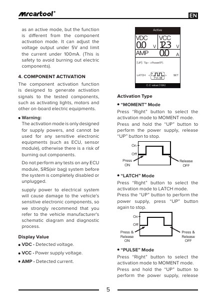
Component Activation supplies battery power through the probe. Use it only for a component the schematic and service procedure explicitly permit to be powered externally. Confirm polarity, normal current and any internal electronics. In Set, use Up/Down to choose a breaker limit from 1–18 A; set it at or below the component’s allowed test current, not automatically at 18 A. Never activate a starter motor, ECU, sensor module, SRS item, network circuit or an unknown in-vehicle wire.
12. Prefer Moment for the first test
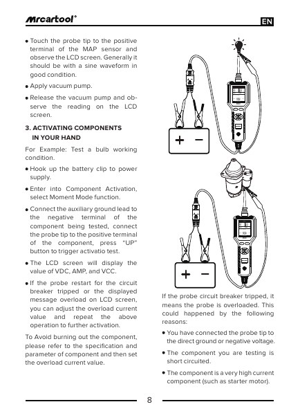
For an approved standalone component, connect the auxiliary ground lead to its negative terminal and the probe to positive. Select Moment with Right, then hold Up only long enough to observe operation; release Up to stop. Watch VDC, VCC and AMP. Stop immediately for excess current, heat, odor, noise, reversed motion or no response. Momentary control gives the operator the fastest release path and is the safest first activation choice.
13. Use Latch or Pulse only when required
In Latch, one Up press starts power and another stops it, so the output can remain live after the operator releases the key. Pulse repeatedly switches power in the illustrated 0.5-second pattern until stopped. Use either only when the exact component procedure requires sustained or pulsed power, the circuit can tolerate it and the probe cannot move. Keep one hand ready to stop and never leave the tester unattended.
14. Treat an overload as a stop condition
If current exceeds the Set value, the B550 cuts output. Release the control and remove the probe. Check for direct ground, reversed connection, a shorted component, a protected electronic driver or a load whose starting current exceeds this tool’s safe use. Do not raise the limit merely to make the test continue. Repeated trips, restart, heat, odor or discoloration means the setup or tool requires inspection before reuse.
Troubleshoot unexpected results
| Symptom | Check first |
|---|---|
| No startup or work light | Battery condition, red/black polarity, clean clamp contact and cable damage |
| VDC is plausible but circuit fails under load | Use the specified loaded voltage-drop test; open-circuit voltage is insufficient |
| Resistance is unexpectedly low | External power, parallel paths, wrong reference or component not isolated |
| Scope trace is unstable | Ground reference, probe contact, display scale, circuit state or need for a higher-spec scope |
| 0–5 V output alarm sounds | Disconnect; check wrong pin, short, opposing voltage or load above 100 mA |
| Activation current rises rapidly | Release immediately; verify polarity, component condition and current limit |
| Breaker trips | Do not increase the setting; find direct ground, short, protected circuit or excessive load |
| Firmware update will not start | Use the official update tool, stable USB connection and exact current instructions away from vehicle testing |
Disconnect and store
Exit every output mode, confirm activation has stopped and remove the probe from the circuit. Turn ignition off and stop the engine. Disconnect black negative, then red positive, preventing either clamp from touching bodywork or the other clamp. Inspect the probe and cable for heat or damage, clean the dry exterior with a mild-detergent cloth and store the tip protected without tight cable bends.
Final B550 checklist
- Exact schematic, pin, expected value and safe circuit state identified
- Eye protection, ventilation, wheel restraint and parking brake in place
- Probe, cable, clamps and auxiliary ground inspected
- Red clamp on battery positive and black clamp on negative
- Mode, unit, scale and ground reference confirmed before contact
- VDC measurement made passively before any active output
- Resistance or diode path de-energized and isolated as required
- Scope and Hertz signal within the documented low-voltage use
- 0–5 V output used only on an identified signal below 100 mA
- Component polarity and normal current known before activation
- Breaker set from 1–18 A no higher than the permitted test current
- Moment used first; Latch or Pulse used only when specifically required
- Any overload, heat, odor or abnormal response stops the test
- All output stopped before probe and battery clamps are removed
The B550 is most effective when its modes are used in a strict order: identify, observe, compare and only then stimulate. Passive VDC, resistance, diode, scope and frequency checks establish evidence without intentionally driving the circuit. The 0–5 V and activation outputs can answer a narrower diagnostic question, but only with a known pin, known load and conservative limit. Treat the displayed current and every protection trip as information—and stop before a useful test becomes a new fault.



Comments 0
Questions, fixes, and real-world diagnostic notes from readers.
Be the first to share a diagnostic result or ask a follow-up question.