
How to Use the MRCARTOOL V30 Fuel Injector Tester

The MRCARTOOL V30 fuel injector tester is a portable pulse driver for an injector removed from the engine. It supplies an electrical command while a separate, compatible fluid source lets you observe injector action, leakage and spray. It does not identify the injector automatically, regulate test-fluid pressure by itself or turn a spray pattern into a complete diagnosis. A useful test depends on the correct injector voltage, a secure adapter, controlled fluid pressure and repeatable observation.
Quick answer: First read the panel on the V30 in your hand. The current panel shown on MRCARTOOL’s product page has a Voltage key, 5 V/12 V selection and modes 0–8; the retained 2024 manual describes an earlier 12 V six-mode panel. Do not transfer mode numbers between them. With the engine off, remove and identify the injector, connect the correct lead and adapter, secure the injector and approved test-fluid source, connect red to battery positive and black to negative, select the verified voltage family and pulse mode, then start while observing from outside the spray path.
In this guide
Identify the panel before using any mode number
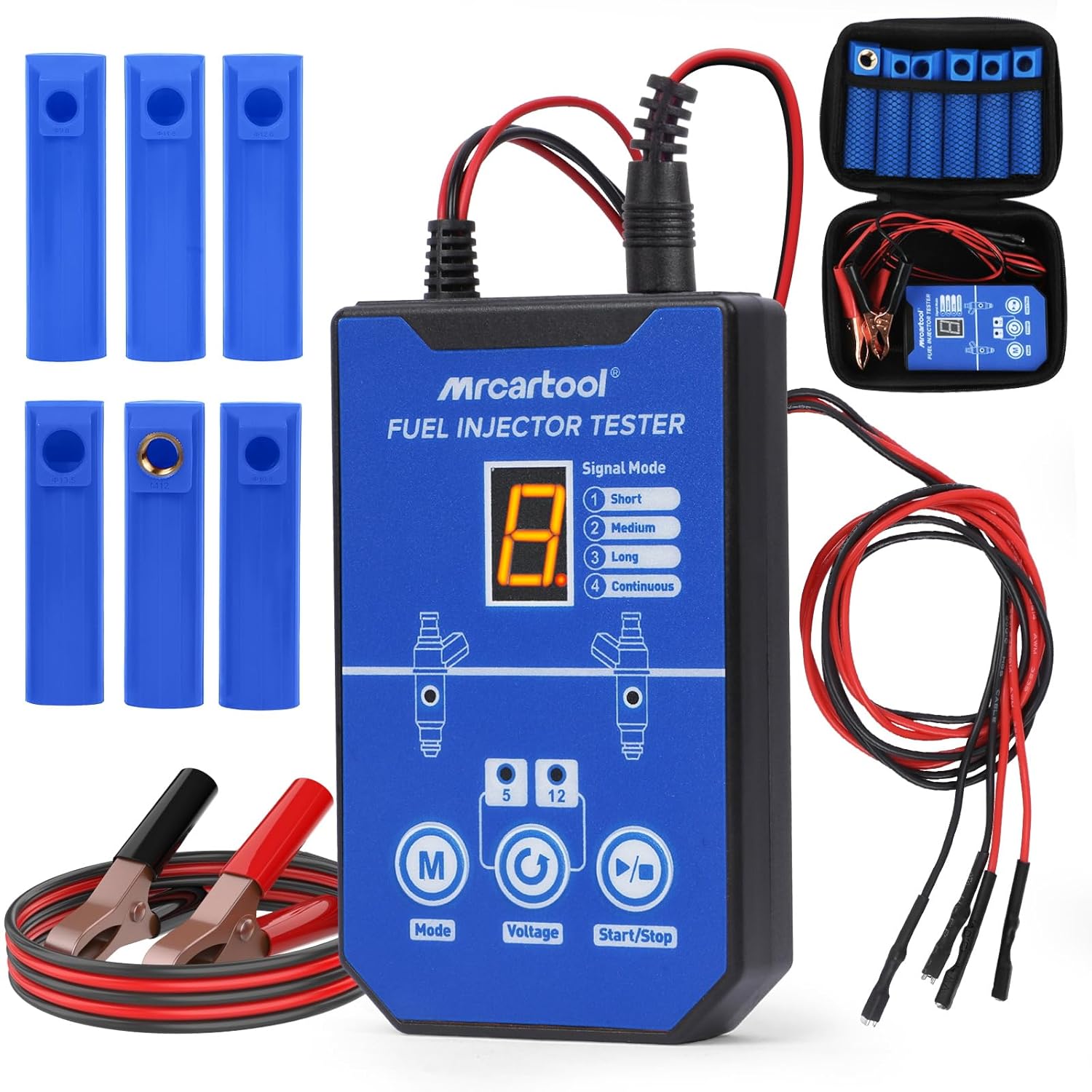
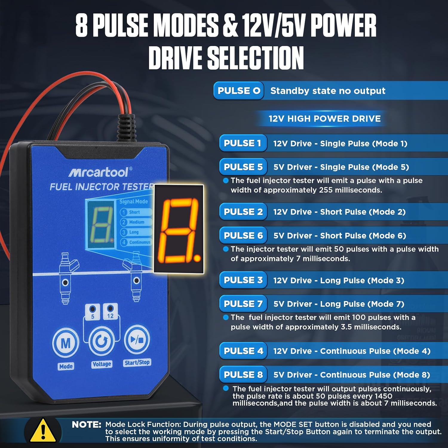
MRCARTOOL’s current V30 product images show a three-button panel labeled Mode, Voltage and Start/Stop. The display uses 0 for standby and 1–8 for pulse programs. Modes 1–4 belong to the 12 V drive family; modes 5–8 repeat the four pulse patterns in the 5 V family. The official TECH MRCARTOOL video also shows this current enclosure and control layout.
The downloadable manual dated 2024 describes a different V30: DC 12 V input, one injector plug, Mode/Start/Stop controls and six programs. Its basic safety and off-vehicle sequence remain useful, but its mode list does not define the current 5 V/12 V panel. If your unit lacks the Voltage key or shows only six modes, use the instructions printed for that delivered version rather than the current-panel table below.
Version boundary: A similar blue case is not enough to identify the control logic. Match the button labels, voltage indicator and displayed mode range. If the delivered label and the online image disagree, stop and obtain the exact manual for the serial/batch before energizing an injector.
Step 1: Identify the injector and define the test
Record the injector part number, vehicle application, cylinder position and connector style before removal. Use controlled service information or injector manufacturer data to determine whether the coil belongs to the V30’s supported 5 V or 12 V family. Do not choose 12 V because it seems stronger, and do not use the tester on a piezoelectric or high-voltage direct-injection unit unless the exact V30 documentation explicitly supports that injector.
Decide what you need to observe. A dry pulse can confirm that an electromagnetic injector clicks, but it cannot prove flow. A wet test can reveal external leakage, nozzle leakage, an uneven spray or a blocked pattern, but only when the separate fluid source, pressure and collection method are controlled. The V30 itself does not display pressure or collected volume.
- Work in a ventilated, ignition-free area. Switch the vehicle off and keep cigarettes, flames, hot lamps, grinders, relays and other spark sources away.
- Wear splash-rated eye protection and fluid-resistant gloves. Aim the injector into a transparent shield or suitable collection vessel, never toward a person or open engine bay.
- Use approved injector test or cleaning fluid compatible with the source, hose, adapter and injector. Never substitute gasoline or an unidentified solvent.
- Inspect the tester case, display, power clips, leads, adapter, injector connector and every O-ring. Replace damaged insulation or sealing parts before connecting power.
- Keep the engine off, remove the injector by the vehicle procedure and restore every disconnected fuel/electrical connection after the work.
Step 2: Lay out and secure the test assembly
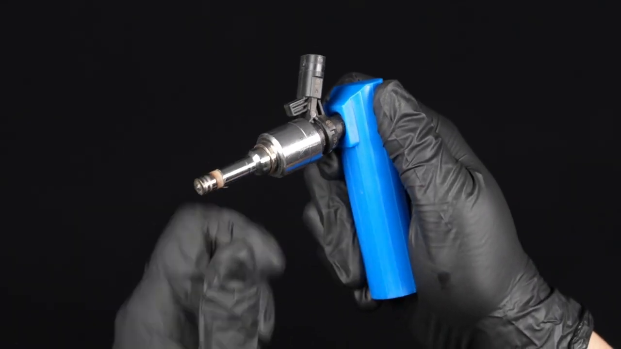
Place the V30 where the display is readable and the leads cannot touch the spray path. Select the nozzle adapter that seats squarely on the chosen approved fluid source and mates with the injector inlet without forcing the O-ring. Similar diameter does not prove compatibility. Support the fluid container upright and use a fixture or guarded hand position that keeps the injector from being ejected by pressure.
Pressure hazard: The V30 controls the injector’s electrical pulse, not the pressure of the can, pump or bench. Never rely on hand force alone to contain an unknown pressure. Stop for a loose adapter, rolled O-ring, damaged can valve, wet electrical connector or any leak outside the injector nozzle.
Step 3: Connect the injector with power still off
Attach the correct V30 injector lead to the injector. On common electromagnetic injectors the legacy manual states that the injector connection is not polarity-sensitive, but do not generalize that sentence to every injector or adapter. Use the delivered lead arrangement and the injector data. Current product imagery shows four output terminals intended to support a two-injector comparison; keep each pair mapped and use only the arrangement supplied with your current unit.
Before connecting the battery, check that the injector, adapter and fluid source remain stable without pulling on the electrical lead. Make the electrical connection last: red clip to the 12 V battery positive terminal and black clip to negative. Keep clips separated, fully seated and clear of rotating or hot vehicle parts. The display should enter standby without the injector being commanded.
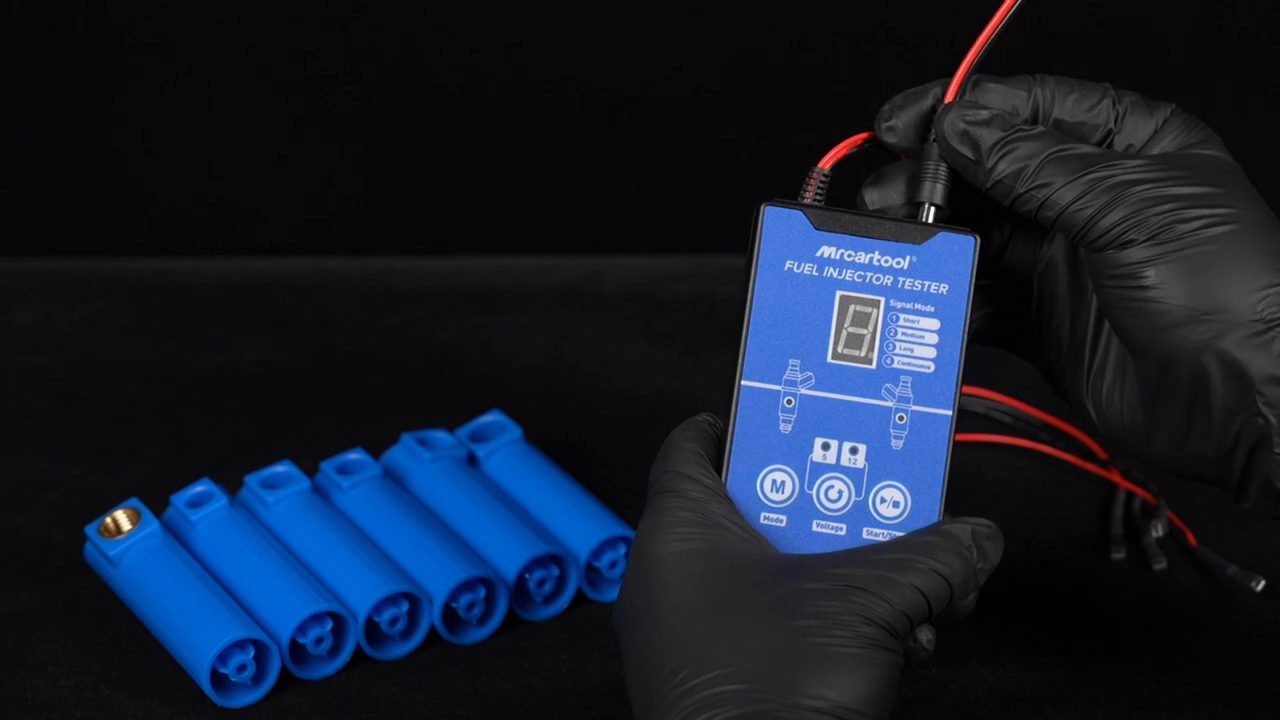
If the display does not light normally, disconnect black first and inspect battery condition, clip contact, polarity, lead damage and protection status. Do not repeatedly tap the clips against the posts and do not open the V30 case.
Step 4: Select the correct voltage family and pulse pattern
On the current panel, use the Voltage key to select the verified 5 V or 12 V drive family, then use Mode to select the pulse pattern. The current product graphic pairs modes 1/5 as single pulse, 2/6 as short-pulse sequence, 3/7 as long-pulse sequence and 4/8 as continuous pulse. Mode 0 is standby with no output. Confirm the displayed number before touching Start/Stop.
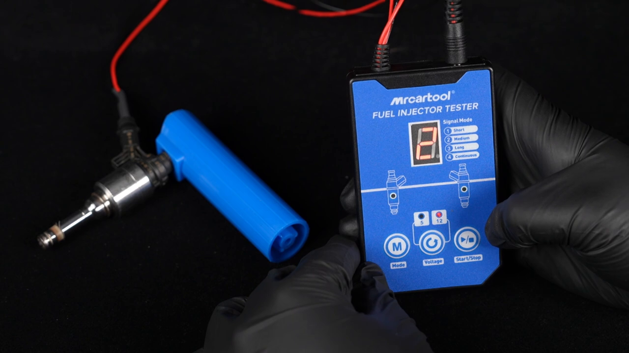
| Current-panel display | Drive family | Use |
|---|---|---|
| 0 | No output | Standby for connection, inspection and mode planning |
| 1 / 5 | 12 V / 5 V | Single pulse for an initial action check |
| 2 / 6 | 12 V / 5 V | Short pulse sequence for repeated opening observation |
| 3 / 7 | 12 V / 5 V | Long pulse sequence for a second controlled comparison |
| 4 / 8 | 12 V / 5 V | Continuous sequence; use only with a secure wet setup and active observation |
The current product graphic also warns that Mode is locked while output is active. Press Start/Stop to end output before changing modes. Do not treat a continuous program as a cleaning shortcut: longer operation increases fluid use and coil heating, and it demands uninterrupted observation.
What if your V30 has the older six-mode panel?
Follow that panel’s delivered manual. The retained older manual describes Mode 1 as one 100 ms pulse each second, Mode 2 as 100 pulses at 5 ms, Mode 3 as 1000 pulses at 3 ms, and Modes 4–6 as idle-, medium- and high-speed simulations. It also describes the display code C231 as the instrument version. Those definitions are included here only to identify the older interface; they must not be applied to current modes 1–8.
Step 5: Start with the least aggressive useful check
For an initial dry action check permitted by the injector procedure, choose the correct voltage family and a single-pulse mode, then press Start while listening for a crisp repeatable click. Stop promptly. No click can result from the injector, the lead, the connection, the selected voltage family or the tester; it is not proof by itself that the injector has failed.
For a wet test, place the nozzle inside the shield or vessel, bring the separate approved fluid source to its documented test condition and inspect every joint for leakage before pulsing. Stand to the side. Start with a brief program, then observe whether the injector opens, whether spray stays inside the vessel and whether the pattern is stable. Stop immediately for external leakage, movement, arcing, smoke, an unusually hot connector or an injector that points outside the collection area.
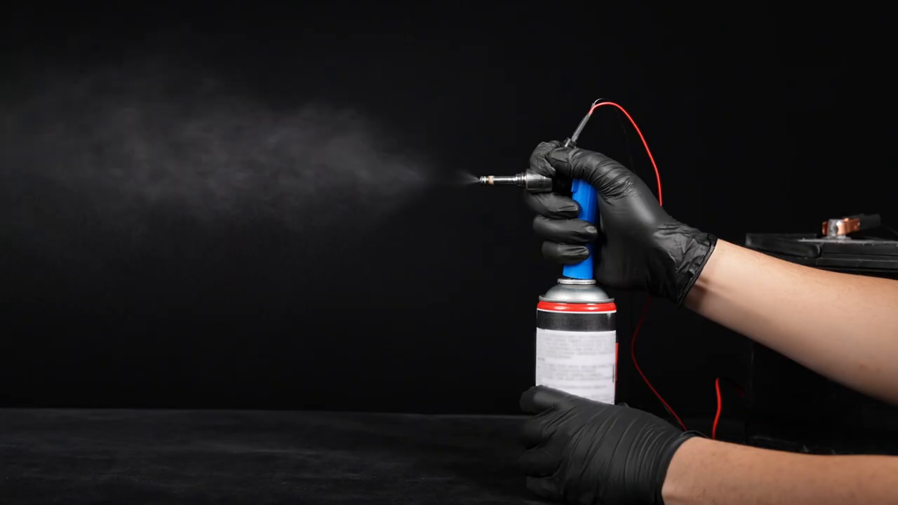
Step 6: Compare results without overdiagnosing
Compare injectors only when part number, fluid, pressure, adapter, voltage family, pulse mode and observation time are the same. A two-injector setup can make a difference easier to see, but first swap leads or positions under a controlled, depressurized setup. If the weak result follows the channel, investigate the tester lead or connection; if it follows the injector, repeat the injector check before making a replacement decision.
- Electrical action: a repeatable click confirms movement, not correct flow.
- Closed leakage: fluid at the nozzle before a commanded pulse may indicate a sealing issue, while wetness at the adapter is a setup fault.
- Spray pattern: compare symmetry and stability at the same pressure and pulse program; do not judge from one transient burst.
- Delivery: the V30 has no graduated measurement system, so use a compatible bench or equal collection vessels if the service procedure requires quantity comparison.
- Final verdict: combine the controlled bench result with circuit diagnosis and vehicle data; the portable tester does not reproduce every in-engine condition.
Step 7: Stop, depressurize and restore
Press Start/Stop and confirm the display has returned to a non-output state. Shut off or release the separate fluid source by its own instructions and verify that pressure is gone before separating the injector, adapter or hose. Disconnect the battery negative clip first, then positive. Remove electrical connectors by their bodies and keep wet parts away from the tester.
Collect used fluid in a compatible labeled container, wipe the adapter and injector, inspect the O-rings and store the V30 dry. Reinstall the injector with the vehicle-specified seals, lubricant, fastener procedure and leak check. Restore every fuel and electrical connection disconnected for the test before the engine is started.
When the button layout, voltage marking or accessory set differs, use the current MRCARTOOL manual download page to locate the document for the delivered version before proceeding.
Troubleshooting
| What you see | Check next |
|---|---|
| No display | Battery state, red/black polarity, clip contact, cable damage and whether the tester is protected after a short. |
| Display works but no click | Correct panel version, 5 V/12 V family, standby versus active mode, injector connector and lead continuity. |
| Click but no spray | Approved fluid supply, actual pressure, adapter seal, injector inlet restriction and nozzle direction. |
| Fluid leaks at adapter | Stop, depressurize, inspect fit and O-ring, and use the exact adapter rather than more hand force. |
| Spray changes between runs | Pressure stability, fluid level, pulse mode, injector temperature, adapter movement and collection position. |
| Mode will not change | Output may still be active on the current panel; press Start/Stop, confirm standby, then select again. |
Frequently asked questions
Does the V30 clean an injector by itself?
No. It supplies the electrical pulse. Cleaning or wet testing also needs an approved fluid source, a matching adapter, controlled pressure and safe collection. The V30 does not contain a pump, tank or ultrasonic bath.
Can I connect the V30 to an injector still on a running engine?
No. The retained manual starts with the engine off and the injector removed. Work through the vehicle’s fuel-pressure release and injector-removal procedure, then test off vehicle in a controlled area.
Should I select 5 V or 12 V?
Select only the drive family verified for the exact injector and the current V30 panel. Guessing can overdrive a low-voltage injector or produce a misleading result. If the data is unavailable, do not energize it.
Can I use gasoline in the test?
Use only an approved injector test or cleaning fluid compatible with the injector, adapter and pressure source. Gasoline introduces unnecessary fire and exposure risk and should not be used as an improvised bench fluid.
Why does my manual show six modes?
MRCARTOOL’s current product imagery and the retained 2024 PDF describe different V30 panels. Use the control definitions for the device in your hand. A six-mode manual does not define the current 5 V/12 V modes 0–8.
Final V30 checklist
- Exact injector and 5 V or 12 V drive family verified
- Delivered V30 panel matched to the correct control instructions
- Engine off, injector removed and vehicle fuel pressure handled by the service procedure
- Approved fluid, matching adapter, sound O-rings and guarded collection area ready
- Injector and fluid source independently secure before battery connection
- Red clip on positive, black clip on negative, with leads clear of spray and hot or moving parts
- Single or brief pulse used first; continuous output never left unattended
- Leaks, click, spray and any comparison judged under the same controlled conditions
- Output stopped and fluid source depressurized before disassembly
- Battery negative disconnected first and every vehicle connection restored
The best V30 result comes from controlling what the tester cannot control for you. Identify the hardware version and injector, choose the verified voltage family, secure the fluid side, start with a brief pulse and compare only under repeatable conditions. That makes the portable tester useful without asking one click or one spray burst to prove more than it can.


Comments 0
Questions, fixes, and real-world diagnostic notes from readers.
Be the first to share a diagnostic result or ask a follow-up question.