
How to Use the MRCARTOOL V209 Fuel Injector Cleaner and Tester

The reliable V209 workflow is a sequence, not a single button: identify the injector and its electrical requirements, clean it in the ultrasonic tank with dedicated cleaning fluid, move the dry injector to the test rail, fill the separate test-fluid circuit, secure every mechanical and electrical connection, select the correct drive voltage, then compare leakage, spray pattern and collected volume. The MRCARTOOL V209 fuel injector cleaner and tester can run four channels together, but a four-way comparison is useful only when all four channels are installed and configured consistently.
Quick answer: Keep ultrasonic cleaning fluid and injector test fluid in their own circuits. Never run the ultrasonic tank dry. Lubricate sound injector O-rings lightly, blank unused rail outlets, clamp the distributor and injectors squarely, connect the signal leads only after the assembly is secure, and choose 12 V, 70 V or 120 V only from verified injector data. Set test pressure from the injector or vehicle specification; the manual’s 0.25–0.30 MPa example is a general electronic-injection reference, not a universal GDI setting.
In this guide
Know what the V209 is controlling
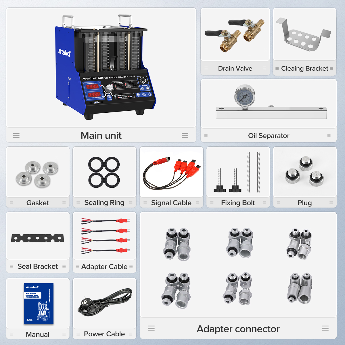
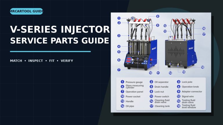
The V209 combines two different processes. Ultrasonic cavitation acts on injectors placed in the stainless cleaning tank. The test side uses a pump, distributor, signal leads and four 110 ml graduated cylinders to simulate operating conditions and compare injector behavior. Cleaning fluid belongs in the ultrasonic tank; test fluid belongs in the machine’s test circuit. Mixing them, or substituting gasoline, kerosene or an unapproved reagent, can damage seals, lines and the pump.
The delivered machine must also match the local supply. The English manual lists a 220 V ±10%, 50 Hz working environment, while current product imagery presents 110 V and 220 V variants. Read the nameplate on the unit in front of you and use a correctly grounded outlet; do not choose a supply from a storefront image.
- Work in a bright, dry and ventilated area with no cigarettes, sparks, flames or hot ignition sources nearby.
- Wear splash-rated eye protection and fluid-resistant gloves. Keep absorbent material and the fluid safety information within reach.
- Inspect the power cord, fuel hose, pressure gauge, glass cylinders, rail, adapters and signal leads. Stop for cracks, damaged insulation, swollen seals or a connector that must be forced.
- Identify each injector by part number and application. Verify electrical drive type, approved voltage, pressure range and connector before it reaches the tester.
- Check every O-ring. Replace a cut, hard, flattened or swollen seal rather than trying to make pressure overcome a poor seal.
Stop: The V209 offers 12 V, 70 V and 120 V drive selections. Those are not three performance levels. An incorrect selection can damage the injector or machine. If the injector’s drive requirement is unknown, do not energize it.
Step 1: Pre-clean and arrange the injectors
Remove the injectors from the vehicle according to the vehicle procedure, keep them identified by cylinder, and remove loose exterior contamination with approved cleaning fluid and a soft cloth. Do not let dirt enter an inlet or nozzle. If you intend to compare several injectors, keep the same set together and record any visible damage before cleaning.
Step 2: Load the ultrasonic tank
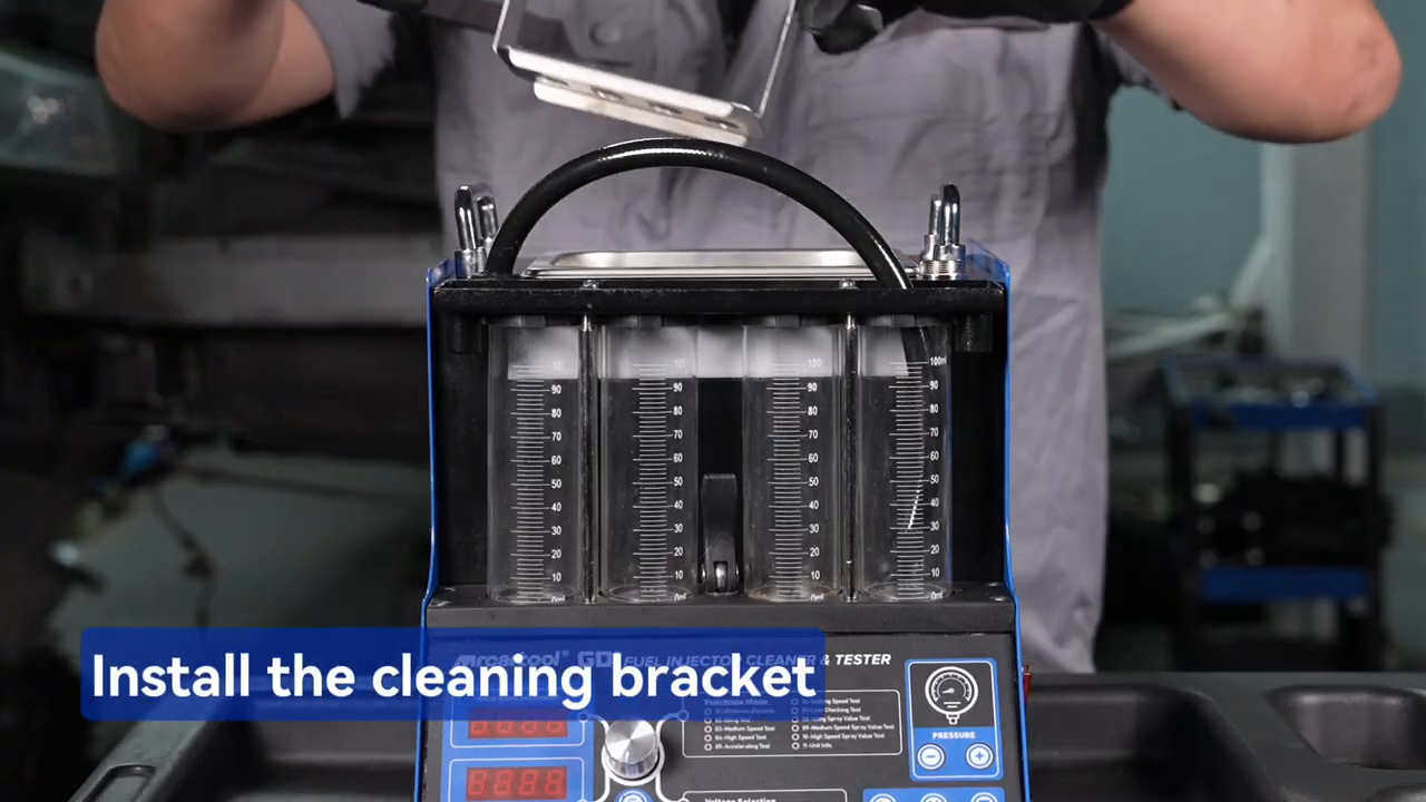
Place the supplied cleaning bracket in the ultrasonic tank and position the injectors in its holes. Add only injector-specific ultrasonic cleaning fluid. The manual says the fluid should cover the bottom of the cleaning bracket; it must be present before ultrasound is enabled. Keep the electrical connectors and any component not approved for immersion above the fluid.
Turn on the correctly grounded machine, select Ultrasonic Cleaning, and set the cleaning time. The V209 control lets the operator edit time and the heating state with the knob, then select Work to start. Watch the tank rather than walking away. Pause or stop if the fluid level is wrong, the bracket moves, or an injector is not supported.
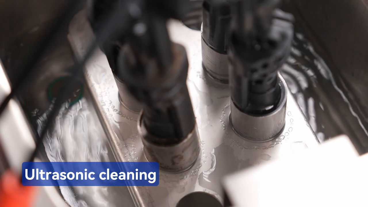
At the end of the countdown, the machine stops automatically. Remove the injectors carefully, let excess cleaning fluid return to the tank, and wipe them with a clean soft cloth. The injectors must be clean and externally dry before they are mounted above the test cylinders.
Step 3: Fill the separate test-fluid circuit
Confirm the oil-drain handle is in the open position. Use the supplied funnel to add injector test fluid through the viewing window slowly enough to prevent overflow. The manual calls for approximately one 1000 ml bottle per fill. Watch the level window and the work surface for leakage. Do not pour this test fluid into the ultrasonic tank.
The V209 manual lists a 1300 ml fuel-tank volume and a 0–0.6 MPa adjustable system-pressure range. Those machine limits do not tell you what an injector should receive. The injector specification remains the controlling value.
Step 4: Build a square, sealed rail assembly
Choose the push-in oil connectors that match the injector inlets and install them in the oil separator/distributor. If fewer than four injectors are being tested, seal every unused distributor opening with the supplied plug. Apply only a light film of compatible lubricant to sound injector O-rings, then insert the injectors in the correct orientation without cutting or rolling a seal.
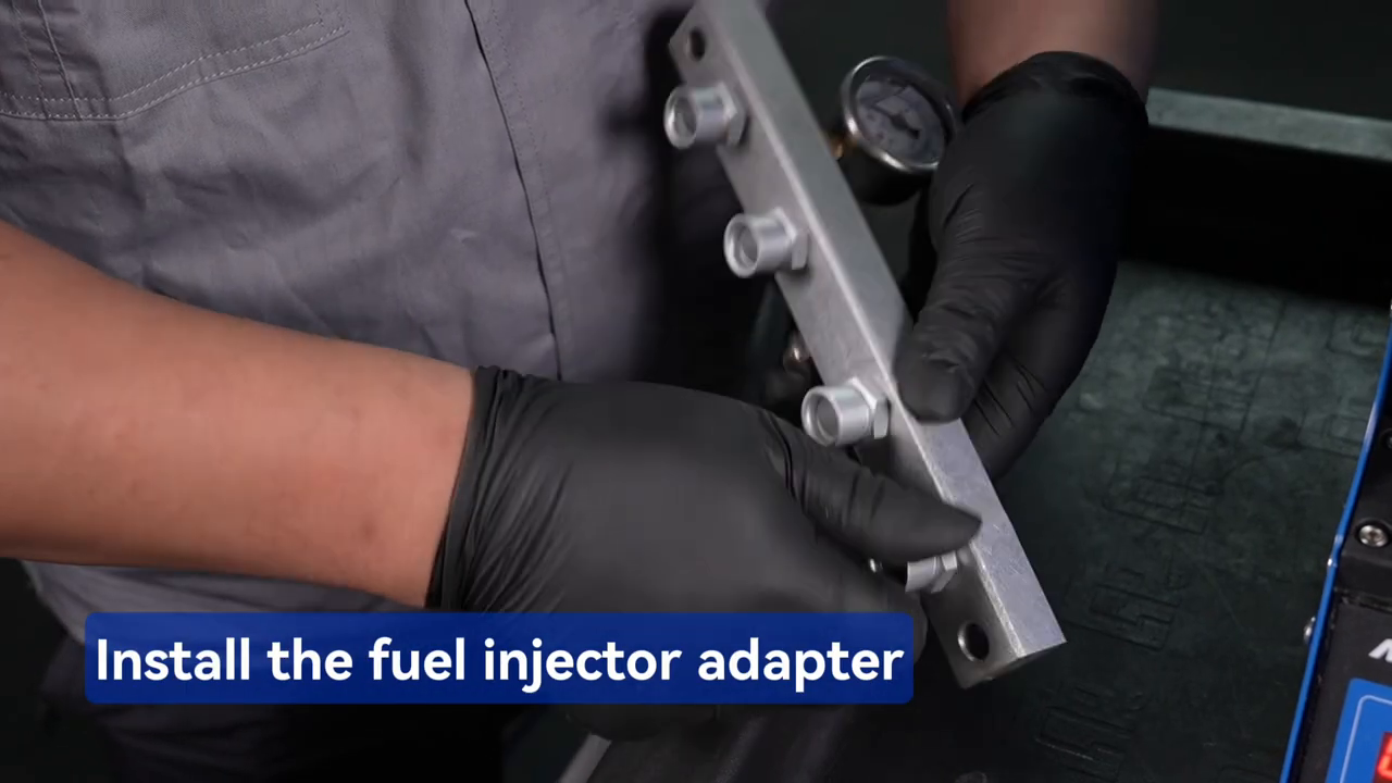
Place the distributor and injectors horizontally on the upper support. Install the locking rods at both ends and tighten them evenly so the assembly sits squarely over the cylinders. Do not use the rods to pull a misaligned injector into place. A tilted rail can side-load an O-ring, direct spray outside a cylinder or make four volume readings incomparable.
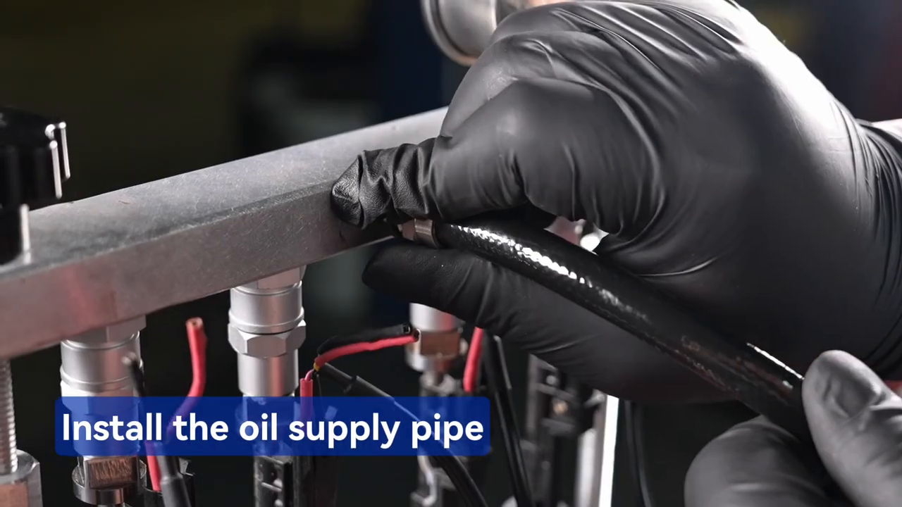
Step 5: Connect signal leads and verify every channel
With no test running, connect the V209 signal harness to the machine and then to each injector using the verified adapters. Route the leads away from wet areas, sharp edges and the spray path. Map lead 1 to cylinder 1, lead 2 to cylinder 2, and so on. Before continuing, gently check that the distributor, injector bodies, supply hose and leads can remain in place without a person holding them.
Do not start yet: Stop if an O-ring is visible outside its seat, an unused outlet is open, a cylinder is not under its nozzle, the rail rocks, a hose begins crooked, or any signal connector is wet.
Step 6: Select electrical and timing parameters
Use the function knob to choose the test item, then set only the parameters requested by that mode. For the idle-, medium- and high-speed tests, the manual describes working voltage, pulse width and time settings. The acceleration and variable-speed programs automate parts of the speed sequence. Treat those simulations as controlled bench comparisons; they do not recreate every electrical, fuel-pressure and thermal condition inside the engine.
- Choose 12 V, 70 V or 120 V from verified injector data—not by trial and error.
- Use the required pulse width and test duration consistently across the injectors being compared.
- Leave the drain handle open when observing spray. Close it only when the selected volume-comparison procedure calls for collection.
- Start at the injector’s documented test pressure. The manual’s 0.25–0.30 MPa reference describes a typical electronic-injection example, not a universal value for every injector labeled GDI.
- Raise pressure only with the V209 pressure controls while watching the gauge, rail, hose, seals and cylinders.
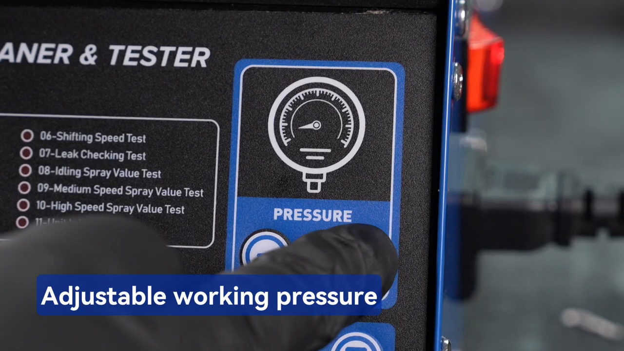
Step 7: Prove sealing before comparing spray
Select Leakage Check Test, set the required time, and start while keeping hands clear of the pressurized assembly. Watch the rail, O-rings, hose connections, injector tips and cylinder area. A droplet at an injector tip may indicate injector leakage; wetness at an adapter or rail is a setup fault. Stop and depressurize before deciding which one you are seeing.
If the external assembly remains dry, proceed to an applicable idle-speed or other low-risk test. Observe whether each injector opens, whether the spray stays inside its cylinder, and whether the pattern is stable. Stop for a loose injector, abnormal pump noise, rapidly falling pressure, fluid outside the cylinders, electrical arcing or a hot connector.
Step 8: Compare pattern and collected volume
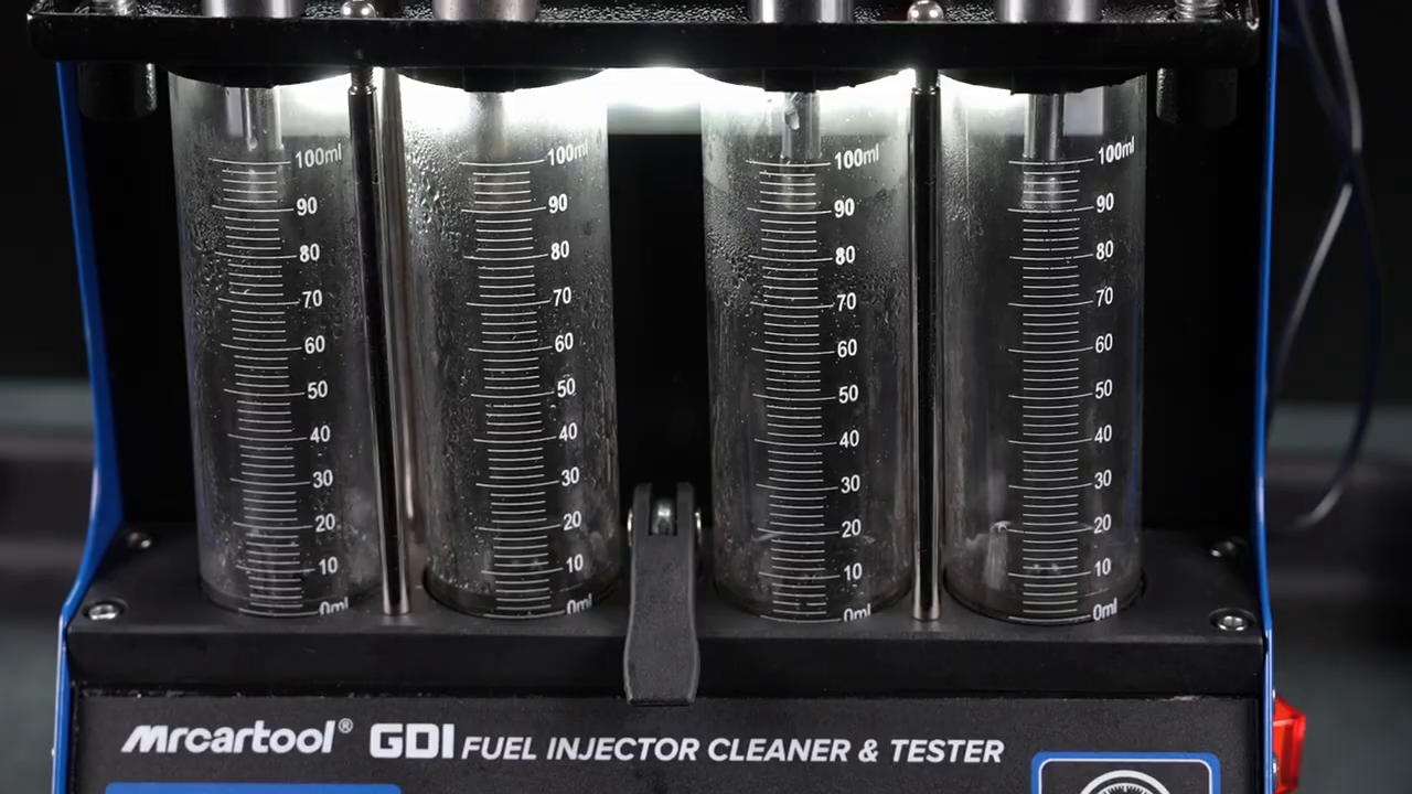
For a volume comparison, begin with the cylinders at the same readable baseline and close the drain handle only as required by the test procedure. Run all channels with identical settings, allow the fluid to settle, then read each meniscus at eye level. Record the values before draining. A meaningful comparison needs the same injector type, rail setup, drive parameters, pressure and time.
Do not reduce the verdict to one number. Use three observations together: no leakage while closed, a consistent atomization pattern while pulsing, and collected volume within the service tolerance for the injector set. A low cylinder can reflect the injector, trapped air, a poor electrical connection, a restricted adapter or a setup leak. Repeat the controlled setup check before condemning a part.
Which V209 function should you choose?
| Menu item | What it helps you observe | Control that must stay consistent |
|---|---|---|
| 01 Ultrasonic Cleaning | Deposit removal in the separate cleaning tank | Approved fluid, immersion and time |
| 02–04 Idle / Medium / High Speed | Pattern and delivery at fixed simulated conditions | Voltage, pulse width, pressure and time |
| 05 Acceleration | Response while the program rises from 800 to 5000 rpm | Verified voltage and secure setup |
| 06 Variable Speed | One sequence at 750, 2500 and 5000 rpm | Verified voltage and common setup |
| 07 Leakage Check | Tip sealing and external setup integrity | Time, pressure and dry observation area |
| 08–10 Spray Value Tests | Collected delivery at idle, medium and high speed | Same baseline, parameters and reading method |
Step 9: Stop, depressurize and drain
Press Stop and wait for the active program to end. Reduce pressure by the documented control sequence, switch off the main power and unplug the machine before releasing the distributor, injectors or hose. Treat every joint as pressurized until the gauge and fluid behavior confirm otherwise.
- Open the appropriate drain path and collect test fluid in a compatible, labeled container. Never drain it into the ultrasonic tank.
- Remove signal leads by their connector bodies, not by pulling the wires. Keep wet adapters away from electrical plugs.
- Return reusable cleaning fluid only if its condition and product instructions permit. Dispose of contaminated fluids as hazardous waste under local rules.
- If the machine will be stored, drain the test tank through the rear release valve. The manual recommends a small clean-fluid rinse before the final drain and refill.
- Wipe the cabinet with a soft dry cloth, inspect glass and seals, and store adapters in labeled positions so the next setup starts from known parts.
Use the current MRCARTOOL manual download page to recheck the delivered manual when the control panel, voltage marking, accessory set or fluid instructions differ from this sequence.
Troubleshooting the first run
| What you see | Check before blaming an injector |
|---|---|
| No display after power-on | Outlet, grounding, nameplate voltage, plug seating and the fuse at the power inlet. Do not open the cabinet. |
| Pressure will not stabilize | Test-fluid level, drain position, supply hose, unused rail plugs, O-rings and external leakage. |
| One injector does not pulse | Verified drive voltage, channel mapping, connector seating, lead damage and whether the fault follows a controlled channel swap. |
| One cylinder reads low | Air, cylinder baseline, rail alignment, adapter restriction, external leakage and identical test parameters. |
| Ultrasonic action appears weak | Approved cleaning fluid, correct level, timer setting, injector placement and whether the tank was ever operated dry. |
| Fluid becomes dirty | Drain and replace it before debris reaches cleaned injectors; contaminated test fluid can clog them. |
Frequently asked questions
Can the V209 test every GDI injector?
No single label proves coverage. Confirm the injector’s mechanical adapter, connector, drive strategy, approved test pressure and the exact V209 configuration. The machine provides 12 V, 70 V and 120 V electrical selections and up to 0.6 MPa system pressure, but those limits do not automatically reproduce every direct-injection system.
Can gasoline be used as test fluid?
No. The manual expressly prohibits gasoline, kerosene and unapproved cleaning or test liquids. Use fluids intended for the V209 task and keep ignition sources away.
Do I close the drain before every test?
No. Keep it open for spray observation unless the selected volume test calls for collection. Closing it at the wrong time can fill the cylinders when you intended only to observe pattern.
Should all four cylinders show exactly the same volume?
Apply the service tolerance for the injector set. The purpose is a controlled comparison, not an assumption of mathematical identity. Verify the setup and repeatability before calling an injector faulty.
Can ultrasonic cleaning run while the tank is empty?
No. The manual warns that dry operation can damage the ultrasonic system. Add the approved cleaning fluid before starting Item 01.
Final V209 checklist
- Correct nameplate supply and protective ground confirmed
- Injector part number, drive voltage, connector and pressure requirement verified
- Cleaning fluid and test fluid kept in separate circuits
- Ultrasonic tank filled before Item 01 is enabled
- Unused distributor outlets plugged and every O-ring seated
- Rail, injectors, supply hose and signal leads independently secure
- Leak check passes before spray and volume comparisons
- All compared channels use the same voltage, pulse width, pressure and time
- Pressure released and power isolated before disassembly
- Results, settings and any setup correction recorded
A useful injector test is a controlled comparison. Clean first, build a dry and square test assembly, choose parameters from verified injector data, prove sealing, then compare pattern and volume under the same conditions. That sequence makes the V209 reading easier to trust and makes a setup error easier to find before an injector is condemned.




Comments 0
Questions, fixes, and real-world diagnostic notes from readers.
Be the first to share a diagnostic result or ask a follow-up question.