
How to Choose and Use AUTOOL OBD2 Extension and Splitter Cables

An OBD2 cable should solve a physical-access problem without becoming a new diagnostic variable. Choose among straight extensions, flat leads, splitters and legacy round-to-16-pin adapters by the vehicle connector, device requirement, routing path and job—not by color or connector shape alone. This guide maps 18 current AUTOOL cable references and gives a repeatable connection workflow.
Quick answer: Use the shortest intact cable that reaches without tension. A straight 16-pin male-to-female extension is for repositioning one supported device; a flat lead is useful only when its routing advantage matters; a splitter exposes more sockets but does not make simultaneous tools electrically or logically compatible; and a BMW, GM or Benz legacy adapter must match the exact vehicle connector and diagnostic procedure. Inspect every terminal, connect with the vehicle and tools in the required state, then verify identity and communication before changing any vehicle data.
In this guide
Choose the cable by task, not appearance
First identify both ends of the intended connection. Most current passenger vehicles present a 16-position SAE J1962-style diagnostic connector, but the existence of that shape does not guarantee that every pin, protocol, module or aftermarket device can be used in every combination. Older round BMW 20-pin, GM 12-pin and Benz 38-pin adapters are separate choices that need exact vehicle service information and a tool that actually supports the target vehicle and control unit.
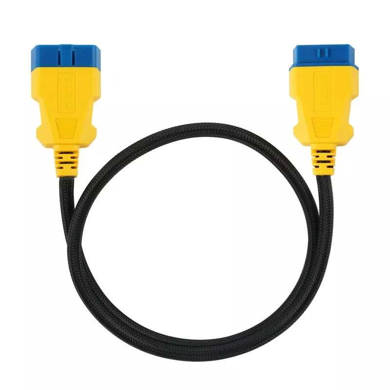
- Straight extension: moves one compatible scanner, logger or interface away from a cramped port. Prefer the shortest length that provides strain relief.
- Flat extension: can route under trim more neatly, but it must not be crushed by a door, cover, seat track or sharp panel edge.
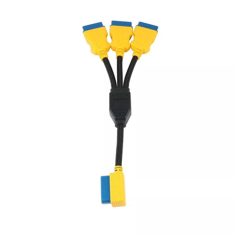
- Splitter: provides two or three physical branches. It does not isolate devices, arbitrate bus traffic or guarantee that two powered tools can share the vehicle network.
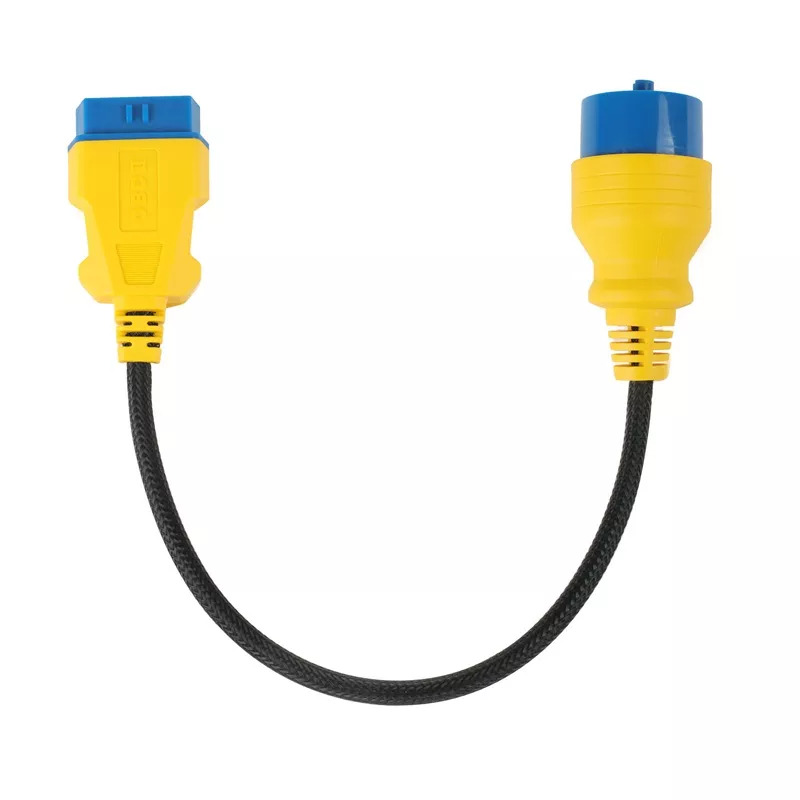
- Legacy adapter: changes the connector form for a named older vehicle family. It does not add software coverage or turn a generic code reader into a factory-level tool.
Length is also a diagnostic choice. Extra cable adds connectors, conductor length and places where a terminal can loosen or be damaged. For routine scanning, use only the length needed to keep the device supported and the vehicle port unloaded. For module programming, coding or any operation that can leave a controller unusable if communication drops, follow the exact tool and vehicle procedure; do not insert an extension or splitter unless that procedure allows it.
Current AUTOOL OBD2 cable selector
| Current reference | Primary selection task | Final check |
|---|---|---|
| 100 cm round OBD2 extension cable | Reposition one compatible 16-pin device without loading the vehicle port. | Confirm both connector ends, length and exact job. |
| 100 cm flat OBD2 extension cable | Low-profile routing where a round cable would obstruct access. | Confirm both connector ends, length and exact job. |
| 150 cm OBD2 extension cable | Reposition one compatible 16-pin device without loading the vehicle port. | Confirm both connector ends, length and exact job. |
| 20 cm reinforced OBD2 extension cable | Reposition one compatible 16-pin device without loading the vehicle port. | Confirm both connector ends, length and exact job. |
| 35 cm 1-to-2 OBD2 splitter | Multiple physical sockets; verify whether simultaneous devices are allowed. | Confirm both connector ends, length and exact job. |
| 35 cm 1-to-3 OBD2 splitter | Multiple physical sockets; verify whether simultaneous devices are allowed. | Confirm both connector ends, length and exact job. |
| 36 cm reinforced OBD2 extension cable | Reposition one compatible 16-pin device without loading the vehicle port. | Confirm both connector ends, length and exact job. |
| BMW 20-pin to 16-pin adapter | Legacy connector conversion; confirm exact vehicle, pinout and scanner coverage. | Confirm both connector ends, length and exact job. |
| GM 12-pin nylon adapter | Legacy connector conversion; confirm exact vehicle, pinout and scanner coverage. | Confirm both connector ends, length and exact job. |
| 60 cm enhanced OBD2 extension cable | Reposition one compatible 16-pin device without loading the vehicle port. | Confirm both connector ends, length and exact job. |
| 14 cm OBD2 extension cable | Reposition one compatible 16-pin device without loading the vehicle port. | Confirm both connector ends, length and exact job. |
| Flexible OBD2 extension cable | Reposition one compatible 16-pin device without loading the vehicle port. | Confirm both connector ends, length and exact job. |
| 1.5 m OBD2 extension cable | Reposition one compatible 16-pin device without loading the vehicle port. | Confirm both connector ends, length and exact job. |
| 50 cm 1-to-3 OBD2 splitter | Multiple physical sockets; verify whether simultaneous devices are allowed. | Confirm both connector ends, length and exact job. |
| 30 cm OBD2 extension cable | Reposition one compatible 16-pin device without loading the vehicle port. | Confirm both connector ends, length and exact job. |
| 40 cm 20-pin to 16-pin adapter | Legacy connector conversion; confirm exact vehicle, pinout and scanner coverage. | Confirm both connector ends, length and exact job. |
| GM 12-pin to 16-pin adapter | Legacy connector conversion; confirm exact vehicle, pinout and scanner coverage. | Confirm both connector ends, length and exact job. |
| Benz 38-pin to 16-pin adapter | Legacy connector conversion; confirm exact vehicle, pinout and scanner coverage. | Confirm both connector ends, length and exact job. |
Some current pages describe similar lengths or connector forms. Treat each exact listing as its own reference and inspect the delivered label and connector faces before use. The two 20-pin-to-16-pin references and the two GM 12-pin references should not be assumed identical from their storefront titles alone. Likewise, a 1-to-2 branch and a 1-to-3 branch create different physical arrangements but neither provides device isolation.
How to connect and use an OBD2 extension or splitter cable
Step 1: Define the job before selecting a lead
Write down the vehicle year, make, model and target system; the exact diagnostic device; and whether the job is a read-only scan, data logging, accessory installation or a state-changing service function. Decide why the original port cannot be used directly. If the reason is simply convenience, a short straight extension is usually easier to control than a splitter. If the job involves programming, immobilizer work, bidirectional control or long unattended logging, use only the cabling expressly allowed by the relevant procedure.
Check: The job record names one vehicle, one primary device and a specific reason for adding the cable.
Step 2: Identify both connector ends and the required length
Compare the vehicle-side connector, cable-side connector and device plug. A normal extension should present one male and one female 16-position connector in the intended orientation. A legacy adapter must match the exact documented round or rectangular vehicle connector and the scanner interface. Measure the route with steering, seat travel and panel fit in mind; do not buy extra length merely because it is available.
Check: Both ends, keying and minimum usable length are known before connection.
Step 3: Inspect housings, pins and strain relief
Under good light, inspect each housing for cracks, heat damage or distorted keying. Look straight into the connector faces for bent, recessed, spread, corroded or contaminated terminals. Flex the cable gently near both strain-relief boots; exposed conductor, a loose boot or an intermittent connection removes the lead from service. Never straighten an unknown live terminal with a metal tool.
Check: Every terminal is aligned and every housing, latch, boot and conductor is clean, dry and intact.
Step 4: Put the vehicle and devices in the required state
Park securely, provide ventilation where needed and stabilize battery voltage when the procedure calls for it. Shut down the scanner, logger and any secondary accessory before building the physical chain unless the exact equipment instructions specify another sequence. Keep chargers in a vehicle-safe mode approved for the operation. Do not use an extension as a reason to place a powered device on the floor, pedals or driver controls.
Check: Vehicle power is stable and all devices are in the documented pre-connection state.
Step 5: Locate the vehicle diagnostic connector without pulling the harness
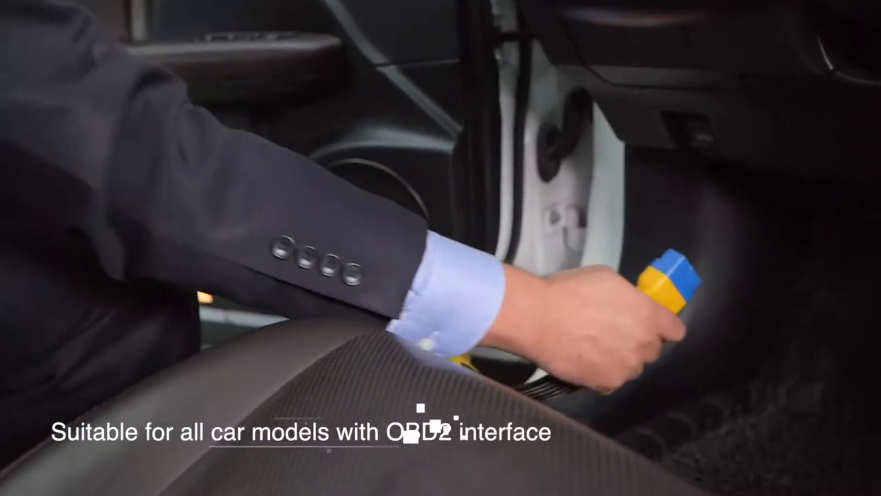
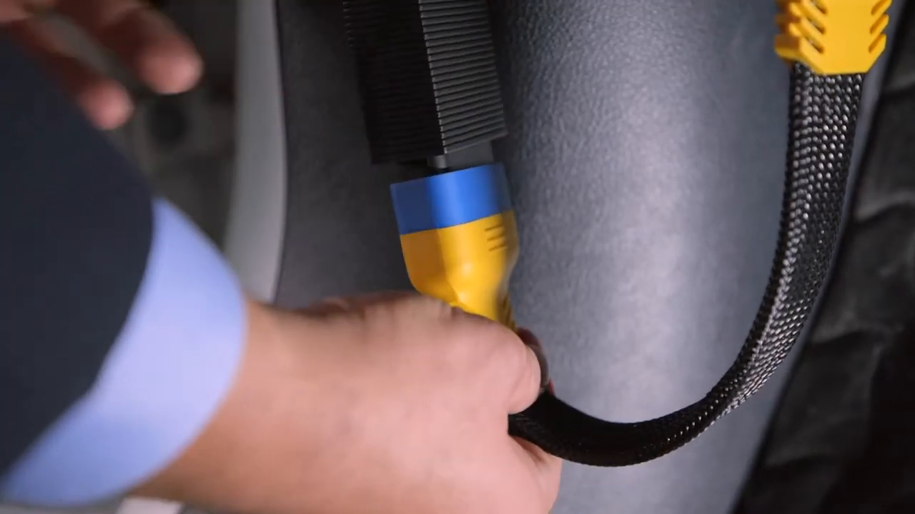
Use vehicle service information to locate the diagnostic connector and remove only the necessary trim. Support the connector if its mounting is loose. Do not tug the vehicle harness toward the driver, probe unused cavities or substitute a visually similar nearby connector. The official AUTOOL demonstration shows a typical under-dash 16-pin location, but actual access and mounting vary by vehicle.
Check: The correct vehicle connector is positively identified, accessible and mechanically supported.
Step 6: Seat the extension or adapter by its housings
Align the keys and push the male connector straight into the vehicle socket using the housing, not the wire. Stop if it will not seat with normal hand pressure. Connect the primary diagnostic device to the opposite end, again supporting both housings. A legacy adapter may require a different sequence or ignition state, so follow the exact vehicle and tool procedure instead of copying the 16-pin demonstration.
Check: Both joints are fully seated with no forced keying, displaced terminal or load on the vehicle connector.
Step 7: Route the cable away from controls and damage zones
Provide a relaxed bend and enough slack for access, then secure the lead away from pedals, steering linkage, seat rails, sharp trim, heater outlets and door seals. Do not close a panel on the cable or leave a loop where a shoe can catch it. The device should rest on a stable surface or approved mount so its mass cannot pull on either connector.
Check: The route stays visible, strain-free and clear through the full movement needed for the job.
Step 8: Add a splitter branch only after checking coexistence
If the job genuinely needs a splitter, connect and verify the primary device first. Confirm from the device and vehicle procedures whether a second interface may share the bus and power supply. Then power down as required before adding the second branch. Do not assume an empty socket is harmless: another interface can wake modules, load the diagnostic supply, transmit on the bus or interfere with programming and logging.
Check: Every connected branch has a named purpose and documented permission to coexist; unused branches are protected.
Step 9: Verify vehicle identity and communication before changing data
Power and start the primary diagnostic session in the required order. Confirm the displayed VIN or vehicle identity, selected module and baseline network status. Save initial fault codes and relevant data before clearing anything. Wiggle-testing a cable during a critical operation is unsafe; if communication changes with gentle stationary inspection, stop and diagnose the connector chain before proceeding.
Check: The tool identifies the intended vehicle or module and maintains stable read-only communication.
Step 10: Exit the session and disconnect in a controlled order
Finish the diagnostic session normally, stop logging and return the ignition to the state required for disconnection. Shut down attached devices, remove the device-side connector by its housing, then remove the vehicle-side plug without pulling the wire. Inspect the vehicle socket for a pushed-back terminal, refit trim and protective caps, and store the cable with broad coils rather than tight bends.
Check: The vehicle connector and trim are restored, all pins remain aligned and the cable is clean and strain-free in storage.
What to check when communication becomes unstable
A cable is only one part of the communication path. Do not immediately condemn the vehicle module or try random adapter combinations. Return to the last simple, known configuration and change one variable at a time. If a critical programming or coding operation has already started, follow the tool’s recovery procedure rather than unplugging the cable.
- Remove splitters and secondary devices, then test the primary tool directly at the vehicle connector if the procedure allows it.
- Confirm vehicle battery voltage, diagnostic-connector power and ground, tool power and the required ignition state using exact service information.
- Inspect every added male and female terminal for spread contacts, pushed-back pins, contamination and loose housing fit.
- Confirm that a legacy adapter matches the exact vehicle connector and that the scan tool has software coverage for the target module.
- Compare with another known-good, correctly specified cable only after recording the original configuration and symptoms.
Stop: Disconnect and investigate before continuing if a connector becomes hot, insulation smells or softens, a terminal arcs, the cable is crushed or cut, vehicle systems wake or cycle unexpectedly, voltage is unstable, or communication drops during a state-changing operation. Do not bridge pins or back-feed an unknown terminal to make the connection work.
Frequently asked questions
Does a longer OBD2 extension improve scanner performance?
No. Length only changes reach and routing. Extra length adds conductor resistance, more cable to damage and more opportunity for an intermittent connection. Use the shortest correctly specified lead that removes strain from the port and keeps the device safely positioned.
Can I run two scan tools from an OBD2 splitter?
Only when the exact vehicle and both device procedures allow simultaneous use. A splitter usually connects branches to the same power and communication lines; it is not an isolator or traffic manager. Two interfaces can interfere with each other or increase battery load.
Can I use an extension cable while programming a module?
Do so only when the vehicle and programming-tool procedure expressly allows that cable and configuration. A momentary connection loss during programming can leave a control unit unusable. Direct, stable connections are normally the lower-risk configuration.
Will a BMW 20-pin, GM 12-pin or Benz 38-pin adapter give my scanner full coverage?
No. The adapter only provides a physical connection path. The scanner still needs correct software, protocol and control-unit coverage for the exact vehicle, and the adapter pinout must match the documented diagnostic connector.
Why does the scan tool work directly but fail through the extension?
Inspect the extension’s male and female terminals, latch fit, conductor continuity and strain relief. Remove other devices and compare in the same vehicle state. If moving the cable changes communication, stop using it until the physical fault is identified.
Final OBD2 cable checklist
- Vehicle, target module, primary device and exact job are identified
- Cable type, both connector ends and minimum length match the task
- Housings, latches, pins, boots and insulation pass inspection
- Vehicle power and ignition state follow the exact procedure
- Cable route avoids pedals, steering, seat rails, doors, heat and sharp edges
- Splitter branches are used only when simultaneous devices are allowed
- Vehicle or module identity and stable read-only communication are verified first
- Session exits normally; devices power down; connectors are removed by their housings
The best OBD2 cable setup is usually the simplest one that solves the access problem. Match the exact connector and job, keep the lead short and mechanically protected, treat every splitter branch as an active electrical connection, and prove stable communication before asking the vehicle to change state.



Comments 0
Questions, fixes, and real-world diagnostic notes from readers.
Be the first to share a diagnostic result or ask a follow-up question.