
How to Use the AUTOOL OBD2 Breakout Box Upgraded Version

The AUTOOL OBD2 Breakout Box Upgraded Version is an OBD2 protocol detector and breakout box. This guide turns the current model-specific controls and official operating sequence into a practical start-to-finish workflow.
Quick answer: Use the Upgraded Version with the ignition off while making the pass-through connections. Identify the exact OBD-II pin and expected condition first, connect the vehicle and scanner without forcing either socket, then switch to the required vehicle state. Check power and grounds before protocol traffic, probe only one identified jack with a correctly configured meter or scope, and remove power before moving leads or disconnecting.
In this guide
Before you start
An OBD2 breakout box exposes battery power, two ground paths and vehicle communication circuits at accessible jacks. A wrong jumper, an ammeter placed across a powered pin, an unregulated external supply or a probe that bridges adjacent jacks can damage modules and wiring. This procedure is for trained automotive professionals working from the exact vehicle connector diagram and test plan; never use the tool while driving.
- confirm the front panel and label identify the Upgraded Version, because display, voltage range and 120-ohm capability differ between versions;
- open the exact vehicle DLC pinout and wiring diagram, including manufacturer-defined pins that are not standardized;
- define the planned vehicle state, reference ground, meter or scope function, expected value and stop condition before connection;
- inspect the DLC, 45cm cable, pass-through socket, 4mm jacks, test leads and external-power lead for damage or contamination;
- secure the vehicle and route the box and cables completely clear of pedals, steering and moving or hot parts; and
- keep every unused jumper disconnected rather than parked across an unidentified jack.
Use the AUTOOL manual download center to locate the current instructions when a manual is available. The delivered model label and current vehicle service information control if an older image or remembered setting differs.
OBD2 Breakout Box Upgraded Version controls and specifications
| Specification or function | Current model |
|---|---|
| Power Cable | Yes |
| Connector | 16-pin OBD interface with built-in input jack |
| Operating Temperature | -20°C-70°C / -4°F-158°F |
| Product | AUTOOL OBD2 Breakout Box Protocol Detector Upgraded Version |
| Diagnostic Port | OBD II |
| Function | OBD2 protocol, power, ground, voltage and signal monitoring through breakout access |
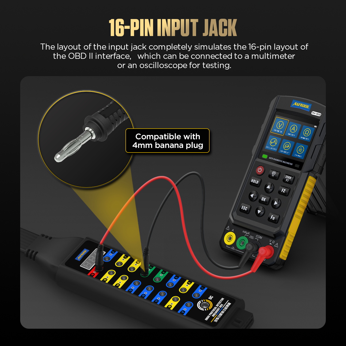
| Multimeter / Oscilloscope Testing | Supported through the 16-pin input jack and 4mm banana plug-compatible access |
| Working Voltage | DC 8V-16V |
| Rated Load | 2.0A specification shown in the parameter image |
| Safety Load Note | Do not connect an external load device exceeding 1A during operation, following the original safety warning |
The Upgraded Version adds the voltage display, LED indications and power cable but not 120-ohm mode. Current first-party records disagree between DC 8-16V and DC 8-30V, so use only the range printed on the delivered unit and its matching manual. The specification table lists a 2.0A load, while every current safety section forbids an external load above 1A; follow the stricter 1A limit. Never bridge pin 16 to pin 4 or 5, and do not assign a function to pins 1, 3, 8, 9, 11, 12 or 13 without the exact vehicle data.
How to use the OBD2 Breakout Box Upgraded Version
Step 1: Confirm the Upgraded Version and the intended test
Read the label and front-panel layout before connection. Confirm that this is the Upgraded Version, identify the exact vehicle DLC pins and decide whether the task is pass-through scanner communication, a voltage/ground check or a scoped signal observation. Do not borrow a display, power or 120-ohm function from another version.
Before moving on, pause and check the connection against the physical labels. A secure-looking connection can still be the wrong port, polarity, range or adapter.
Step 2: Inspect the DLC, cable, jacks and test leads
Keep the ignition off. Check the vehicle connector, 45cm cable, breakout housing, every 4mm jack and each lead for looseness, contamination, bent contacts or damaged insulation. Do not continue if the DLC has overheated terminals or an aftermarket wiring change that has not been identified.
Step 3: Connect the pass-through path with power off
Plug the breakout-box vehicle connector squarely into the OBD-II DLC without forcing it, then connect the diagnostic scanner to the pass-through socket when the test requires a scanner. Route the box so it cannot interfere with pedals, steering or the driver's feet; never operate or read it while driving.
Step 4: Switch to the required vehicle state and make a baseline check
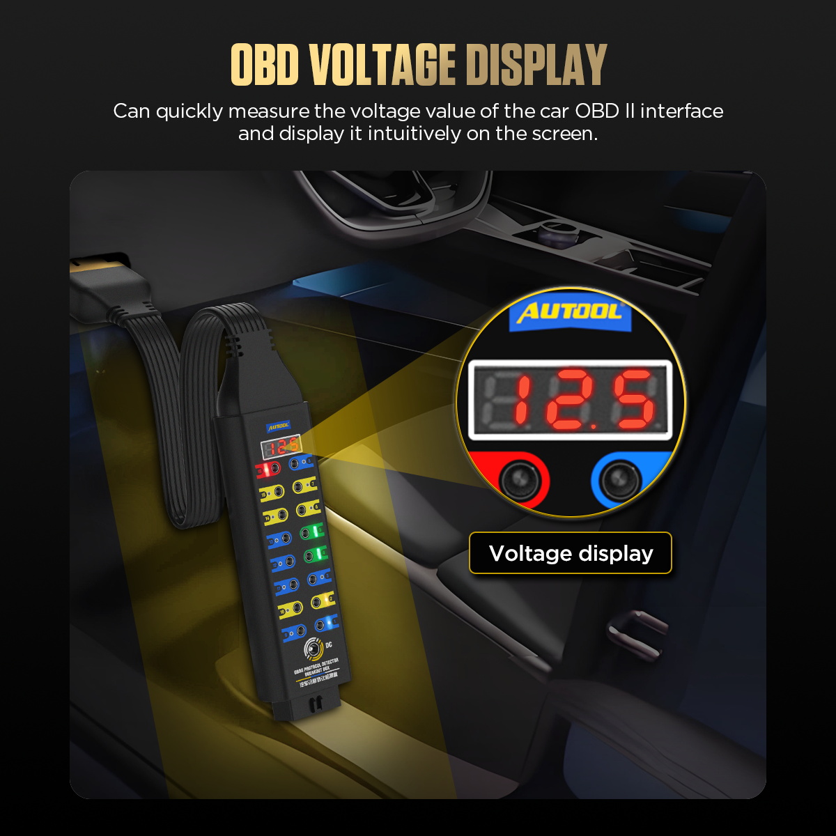
Use the exact service procedure to choose ignition off, ignition on/engine off or running state. Verify pin 16 power and pins 4/5 grounds against the vehicle wiring information before interpreting a network result. Use the built-in display and color-coded LED indications only as an initial pin-state check. Current first-party sources conflict between DC 8-16V and DC 8-30V for this version, so the delivered label and matching manual control the usable voltage boundary.
Step 5: Probe one identified pin without bridging neighbors
Connect a correctly configured multimeter or oscilloscope through the matching 4mm jack. Select meter function, range, reference ground and scope coupling before contact. Never use an amp-input lead across a powered OBD pin, and never bridge pin 16 to pin 4, pin 5 or an unknown circuit.
Step 6: Observe scanner communication or the planned waveform
Run only the communication or electrical check defined before connection. Keep the scanner, meter and breakout leads stable and compare the pin voltage or waveform with the exact vehicle specification and a known-good condition where available. A flashing communication LED or active waveform shows traffic, not that every module or data message is correct.
Step 7: Use external power only under a written backup-power procedure
The DC jack can support specific ECU-memory or bench tasks, but an incorrect source can back-feed or damage vehicle circuits. Verify polarity, regulated voltage, current protection and the exact connection sequence before attaching an external supply. Follow the manual's stricter warning: do not attach an external load above 1A even when a specification table lists a 2.0A load value.
Step 8: Apply the version-only mode or leave it off
This version does not provide the Premium Version's 120-ohm series mode; do not improvise termination with jumpers on the breakout jacks.
Step 9: Shut down, disconnect and restore the DLC
Stop the scan or capture, return the vehicle to ignition off and remove external power before moving any test lead. Disconnect the scanner and breakout box by their housings, inspect the DLC for displaced terminals, then confirm the vehicle starts and communicates normally when the service procedure calls for that check.
Do not end the job at the first plausible indication. Repeat or confirm the observation under the same controlled condition, then restore the vehicle connection and check for leakage, warnings or an abnormal response.
Read and verify the result
Start with the supply conditions: pin 16 power and the integrity of body and signal grounds. Only then assess scanner communication or the planned protocol waveform. A lit or active communication pin proves activity at that point; it does not prove correct messages, network termination, module health or a fault-free vehicle.
- Record the vehicle state, pin number, meter or scope setup, reference ground, value and units so the observation can be repeated.
- A voltage that looks normal with no load can still collapse under a permitted diagnostic condition; follow the vehicle diagnostic tree instead of adding an improvised load.
- An unstable waveform can come from probe setup, reference selection, the breakout connection or the vehicle network. Change one controlled variable at a time.
- Use Premium 120-ohm mode only when a documented bench-CAN topology calls for it; it is not a general in-vehicle reset or repair switch.
Stop immediately for heat, odor, arcing, a loose DLC, an unexpected voltage, a scanner reset, abnormal module behavior, unstable external power or an unidentified pin assignment. Return the ignition to off and remove the external source before moving jumpers, changing meter ports or disconnecting the pass-through path.
Common mistakes and care
- This tool connects directly to vehicle power, ground and communication lines and is intended for trained automotive professionals.
- Do not jumper an unknown circuit, bridge pin 16 to pins 4 or 5, or connect an external load above 1A.
- Stop for heat, odor, unstable power, a moving connector, unexpected module behavior or an unidentified pin assignment.
- Do not assume every colored jack is an LED; the Basic Version uses color coding without built-in signal indication.
- Do not put a meter lead left in an A or mA port across any OBD pin.
- Do not jumper unknown manufacturer-defined pins or use the breakout box to search by trial and error.
- Do not use external backup power until polarity, regulated voltage, current protection and the vehicle-specific sequence are all confirmed.
- Do not disconnect a scanner, scope reference or external supply while the relevant circuit is active.
Frequently asked questions
Can I use the OBD2 Breakout Box Upgraded Version setup from a different AUTOOL model?
No. Similar housings and accessories do not prove identical ranges, controls, power requirements or connection methods. Match the exact model first.
Does one normal result prove the system is fault-free?
No. It proves only that the tested condition was within the chosen acceptance criteria at that moment. Continue the vehicle-specific diagnostic path when the symptom remains.
What should I do when the reading is unstable?
Stop and check power, connection security, sealing, range selection, test-point suitability and vehicle state. Repeat only after the cause of instability is understood.
Final OBD2 Breakout Box Upgraded Version checklist
- Upgraded Version, delivered voltage label and available functions confirmed
- Exact vehicle DLC pinout, test state, expected value and stop condition documented
- Pass-through plugs fully seated and cables clear of all driver controls
- Power and ground baseline verified before communication interpretation
- One identified pin probed with the correct function, range and reference
- External power and all test activity stopped before leads were moved
- DLC terminals intact; normal vehicle start and communication rechecked where required
The Upgraded Version is valuable because it makes the DLC observable without cutting or back-probing vehicle wiring. That access also removes a layer of protection: decide the pin and measurement first, keep the setup passive unless a documented procedure says otherwise, and treat every indication as evidence for the next vehicle-specific test—not as a diagnosis by itself.



Comments 0
Questions, fixes, and real-world diagnostic notes from readers.
Be the first to share a diagnostic result or ask a follow-up question.