
How to Use the AUTOOL DM103 Digital LCR Tweezer

The AUTOOL DM103 is an digital LCR tweezer for passive components. This guide turns the current model-specific controls and official operating sequence into a practical start-to-finish workflow.
Quick answer: Remove all power, prove the board is de-energized and fully discharge every capacitor. Select AUTO or a known L/C/R/diode/continuity mode, choose the required frequency and level, grip one component cleanly, wait for stable primary and secondary values, then repeat under the same conditions.
In this guide
Before you start
The DM103 measures passive components; it is not a live-circuit probe. Work on a dry, de-energized board away from fuel vapor and static-sensitive parts. Capacitors can retain energy after the board is switched off, and parallel circuit paths can make an in-circuit result differ from the component’s isolated value.
- disconnect every supply, backup source and external connector, then verify absence of voltage with an appropriate instrument;
- fully discharge capacitors by the equipment or component manufacturer’s approved method and verify discharge;
- inspect the DM103 housing, OLED, Type-C port and gold-plated tips for damage, contamination or misalignment;
- identify the component type, expected range and whether parallel board paths require one end to be lifted or the part removed;
- decide the mode, frequency and test level needed by the datasheet or same-part comparison; and
- control static electricity and avoid touching the conductive tips or component terminations during measurement.
Use the AUTOOL manual download center to locate the current instructions when a manual is available. The delivered model label and current vehicle service information control if an older image or remembered setting differs.
DM103 controls and specifications
| Specification or function | Current model |
|---|---|
| Accuracy | ±0.5% |
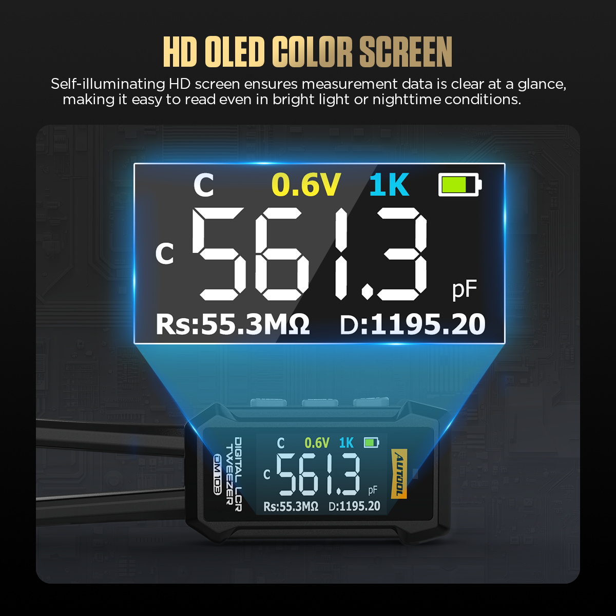
| Resistance Range | 10mΩ-10MΩ |
| Capacitance Range | Auto Mode: 50pF-5mF; Capacitance Mode: 1pF-20mF |
| Inductance Range | Auto Mode: 5μH-60H; Inductance Mode: 1μH-60H |
| Frequency | 100Hz, 1kHz, 10kHz |
| Test Level | 0.3V, 0.6V / 0.6Vrms |
| Test Speed | 1 time / second |
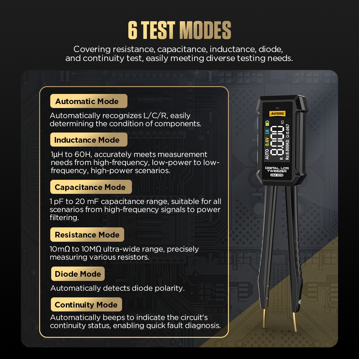
| Test Modes | Automatic, inductance, capacitance, resistance, diode, and continuity |
| Supported Parameters | L, C, R, D, Q, Rs, RS, Z, X |
| Dimensions | 145mm x 30mm / 5.7in x 1.2in |
Stay within the published R, C and L ranges and never apply external voltage to the tips. Frequency and test level are part of the result: values taken at 100Hz and 10kHz are not automatically interchangeable. AUTO recognition identifies a likely passive component but does not certify its health.
How to use the DM103
Step 1: Remove power and prove the board is de-energized
Disconnect every board supply, backup source and external connector. The DM103 is for passive components and must not be used on a live circuit; verify the absence of voltage with an appropriate instrument before touching the tweezer tips to the board.
Before moving on, verify absence of voltage independently and confirm every capacitor has been discharged by an approved method.
Step 2: Discharge every capacitor completely
Use the component or equipment manufacturer’s approved discharge method, then verify discharge. A stored charge can damage the DM103, distort the reading or injure the operator.
Step 3: Inspect the tips and decide whether in-circuit testing is valid
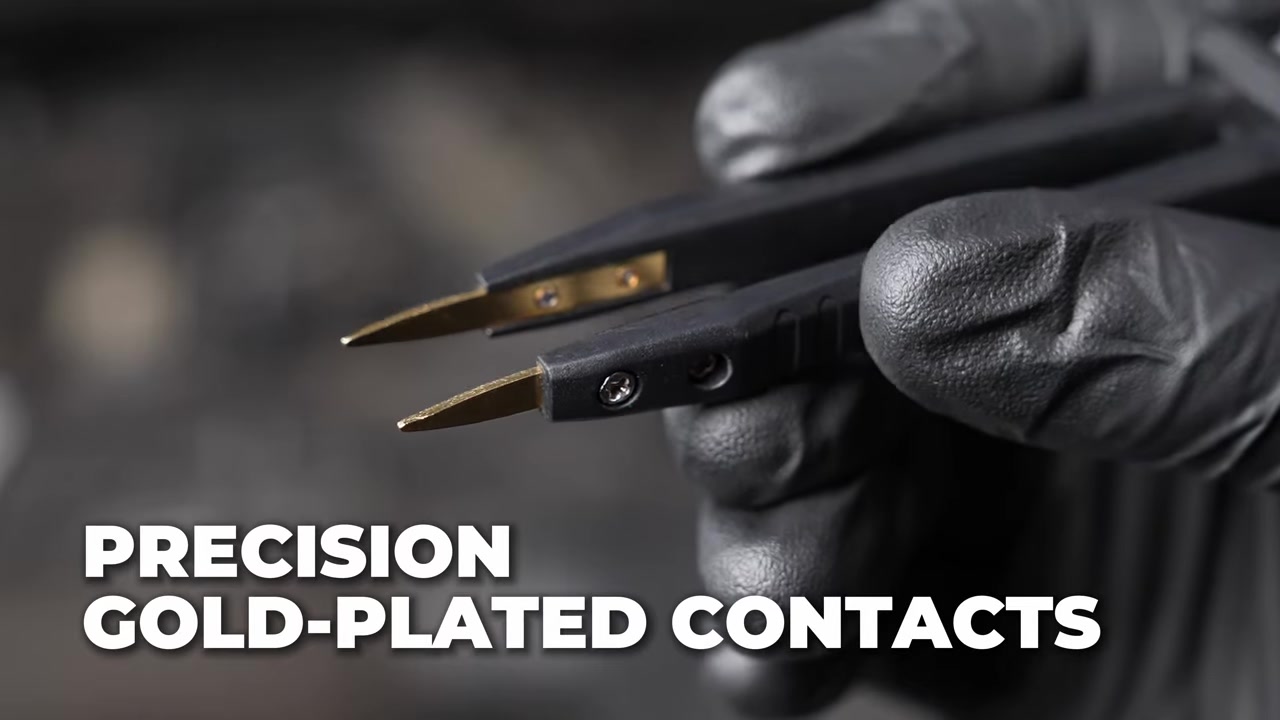
Clean the fine gold-plated tips without abrading them and confirm they align. Parallel paths on a populated board can change resistance, capacitance and inductance readings, so lift or remove the component when the circuit topology makes an in-circuit result ambiguous.
Step 4: Power on and choose AUTO or the known component mode
Press the power/mode key to start. Use AUTO for initial recognition of a passive resistor, capacitor or inductor, or select the dedicated L, C, R, diode or continuity mode when the component type and required test are already known.
Step 5: Choose the test frequency and level deliberately
Select 100Hz, 1kHz or 10kHz and the available test level only when the component specification or comparison method calls for it. Record these settings because L, C, D and Q can change with test frequency and level.
Step 6: Grip one component with clean, stable contact
Place one tip on each component termination without touching adjacent pads or applying sideways force. Keep fingers away from the metal contact area and hold the tweezers still until the primary and secondary values stabilize.
Step 7: Read the primary value and its secondary parameter together
Read the identified L, C or R value together with the displayed Rs, D, Q, Z or X parameter that applies to the selected mode. Use HOLD only after the result is stable, and do not treat an automatically recognized part name as proof that the component is healthy.
Step 8: Repeat under the same conditions and compare
Release and re-grip the component to confirm repeatability. Compare with the component datasheet, service information or a known-good same-part measurement made at the same frequency, level and temperature.
Step 9: Power off, protect the tips and document the result
Long-press the power key to switch off, clean the tips if necessary and store them so they cannot be bent. Record whether the component was tested in circuit or removed, along with mode, frequency, level and the values used for the decision.
Before closing the job, record whether the part was in circuit or isolated together with mode, frequency, level and the stable primary and secondary values.
Read and verify the result
Start with the primary L, C or R value, then interpret the secondary parameter appropriate to that component. D expresses dissipation, Q expresses quality factor, Rs represents series resistance, and Z/X describe impedance behavior. Compare only readings made with the same isolation, frequency, level and temperature conditions.
- A stable result that repeats after releasing and re-gripping the part is stronger than the first displayed value.
- A surprising in-circuit result may come from parallel resistors, capacitors, semiconductors or leakage paths; isolate the component before condemning it.
- D or Q can reveal a difference that a nominal capacitance or inductance value alone does not show, but the component datasheet defines the meaningful test condition.
- Contact contamination, fingertip contact and bent tips can change small-value readings; correct the measurement setup before interpreting the component.
Stop if voltage is detected, a capacitor may still be charged, the tips bridge adjacent pads, the display becomes unstable after repeated clean contact, or the tool or component warms unexpectedly. Remove the tips and make the board safe before changing mode or isolation.
Common mistakes and care
- Do not apply voltage during measurement.
- DM103 is not designed for measuring live circuits.
- Always disconnect power before testing circuit-board components.
- Fully discharge all capacitors before measurement.
- Always discharge capacitors before measurement to prevent device damage and improve reading accuracy.
- Avoid high temperatures, dust, and direct sunlight during use or storage.
- Do not use in humid environments.
- Do not use the DM103 on an energized circuit or assume switching the equipment off discharged every capacitor.
- Do not interpret an in-circuit value as the isolated component value when parallel paths are present.
- Do not compare readings taken at different frequencies, levels or temperatures without accounting for those conditions.
- Do not squeeze, scrape or side-load the fine tips; stable light contact is enough.
- After use, power off and protect the clean tips from impact, contamination and humidity.
Frequently asked questions
Can the DM103 measure a component on a powered circuit?
No. Disconnect every supply, verify the absence of voltage and fully discharge capacitors before the tweezer tips contact the board.
Why does an in-circuit value differ from the part marking?
Other components and leakage paths may be in parallel. Lift one end or remove the part when the circuit topology prevents an isolated measurement.
Which frequency should I use?
Use the component datasheet, service information or same-part comparison condition. Record the selected frequency and level because reactive component values and D/Q can change with them.
Final DM103 checklist
- Board de-energized and absence of voltage verified
- Every capacitor discharged and condition verified
- Component isolation and parallel paths considered
- Mode, frequency and test level recorded
- Primary and secondary values stable and repeatable
- DM103 powered off with clean, protected tips
The DM103 is most useful when the measurement conditions are controlled. A repeatable value plus D, Q, Rs, Z or X can sharpen a board-level decision, but isolation and the component specification still determine what the result means.







Comments 0
Questions, fixes, and real-world diagnostic notes from readers.
Be the first to share a diagnostic result or ask a follow-up question.