
How to Use the FXTUL M3 Motorcycle Diagnostic Tool

The FXTUL M3 motorcycle diagnostic tool can scan supported motorcycle control units, read current and pending fault codes, show freeze-frame and live data, display diagnostic-connector voltage and run supported output or maintenance functions. The reliable order is to confirm the exact M3 kit and vehicle coverage, connect with stable power, save a pre-clear scan, investigate the affected control unit, repair the cause, then clear and rescan only when the evidence supports it.
An M3 is a diagnostic interface, not a universal repair instruction. Connector location, ignition state, supported systems, normal data ranges, active-test prerequisites, relearns and post-repair checks change by motorcycle. Use the exact motorcycle service information at every vehicle-specific decision, and never treat a cleared warning light as proof of a completed repair.
Updated August 28, 2026.
In this guide
- Decide whether this M3 fits the motorcycle
- Prepare the motorcycle and diagnostic record
- FXTUL M3 step-by-step diagnostic workflow
- Use Voltage Detection as a connection check
- Update the M3 software from a computer
- Export a diagnostic log for support
- Troubleshoot without erasing useful evidence
- What a complete M3 diagnostic job looks like
Decide whether this M3 fits the motorcycle
Current M3 bundles and the still-listed M3-A, M3-B and M3-C kits do not contain the same adapter groups. A brand name on a menu or package graphic is not enough to establish compatibility with one model year, connector or control unit.
| Check | Continue when | Stop when |
|---|---|---|
| Tool identity | The housing and installed software identify M3 | The model, edition or software package cannot be confirmed |
| Physical kit | The required adapter is present, labeled and undamaged | A connector must be forced, modified or assembled from uncertain leads |
| Vehicle coverage | The exact make, model, year and target system are supported by the current M3 coverage information | Only a similar model or brand-level claim can be found |
| Service information | You know the diagnostic connector location and required key/engine state | The connector, ignition sequence or access method would be guessed |
| Electrical condition | Battery and support equipment meet the motorcycle procedure and can remain stable through the scan | Voltage is unstable, polarity is uncertain or a support source is not approved for the vehicle |
| Work conditions | The motorcycle is stable, ventilated and protected from unintended movement | Fuel vapor, moving parts, heat, traffic or an unstable stand makes the test unsafe |
Prepare the motorcycle and diagnostic record
Have the exact motorcycle service information, the M3 and correct adapter, a stable power plan allowed by the vehicle procedure, and a way to record the model, VIN where applicable, odometer, complaint, warning lights, battery condition and test conditions. If the complaint is intermittent, write down when it occurs—cold or hot, at idle or under load, after rain, after a repair, or after a low-voltage event.
Inspect the M3 housing, fixed lead, diagnostic connector, adapter leads and pins. Inspect the motorcycle connector for bent or pushed-back terminals, corrosion, contamination, moisture or previous probing damage. Do not use a generic jumper to make two connectors fit.
Before scanning, preserve the vehicle exactly as found. Do not disconnect the battery, clear codes or begin a relearn first; those actions can remove the evidence that points to the original cause.
FXTUL M3 step-by-step diagnostic workflow
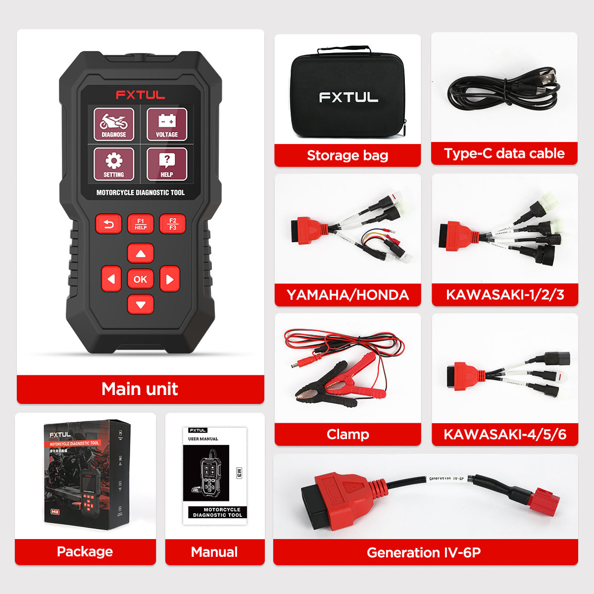
Step 1: Identify the M3 edition, installed software and adapter
Read the product label and compare the physical contents with the kit you own. Older A, B and C packages pair different brand menus with different motorcycle adapters; the newer unified package has a different contents image. Select by the actual kit and current coverage—not by color, connector shape or a marketplace title.
Power the M3 only through an approved vehicle diagnostic connection or a computer connection used as described in the update section. From the main menu, open Help to record the menu, app and software-package versions. Keep those version numbers with the scan record; they matter if the vehicle does not appear or support asks for a log.
Completion check: You have the exact M3 identity, software versions, required adapter label and vehicle coverage in the same job record.
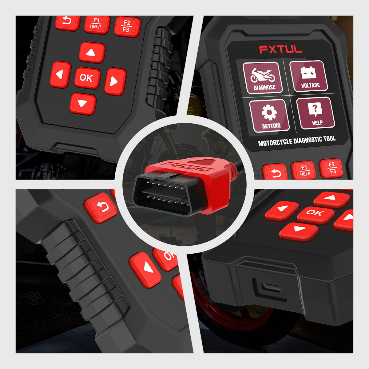
Step 2: Locate and inspect the motorcycle diagnostic connector
Use the motorcycle service information to find the diagnostic connector and expose it without pulling on its wiring. Depending on the motorcycle, access may be under a seat, side panel or another protected area; this article does not assign a universal location.
Confirm the connector pin count and keying against the selected adapter. Look for a capped connector that merely resembles the diagnostic port, added accessories spliced into the circuit, or a terminal that has receded into the housing.
Stop: Do not probe terminals blindly, remove a seal that the service procedure keeps in place, or force a near-fitting adapter.
Step 3: Secure the motorcycle and control electrical load
Place the motorcycle on the stand specified for the job and prevent unintended movement. Work in a ventilated area. Keep loose clothing, leads and hands away from the chain, belts, fans, exhaust and other hot or moving parts if the procedure later requires the engine to run.
Set ignition, engine and accessory loads to the starting condition required by the vehicle procedure. If battery support is specified, use the approved type and connection method. Do not invent a universal voltage threshold from a screenshot; the exact motorcycle procedure controls the acceptable range.
Completion check: The motorcycle is stable, the diagnostic area is accessible, and voltage will not be interrupted by an avoidable load or loose connection.
Step 4: Connect the adapter without loading the terminals
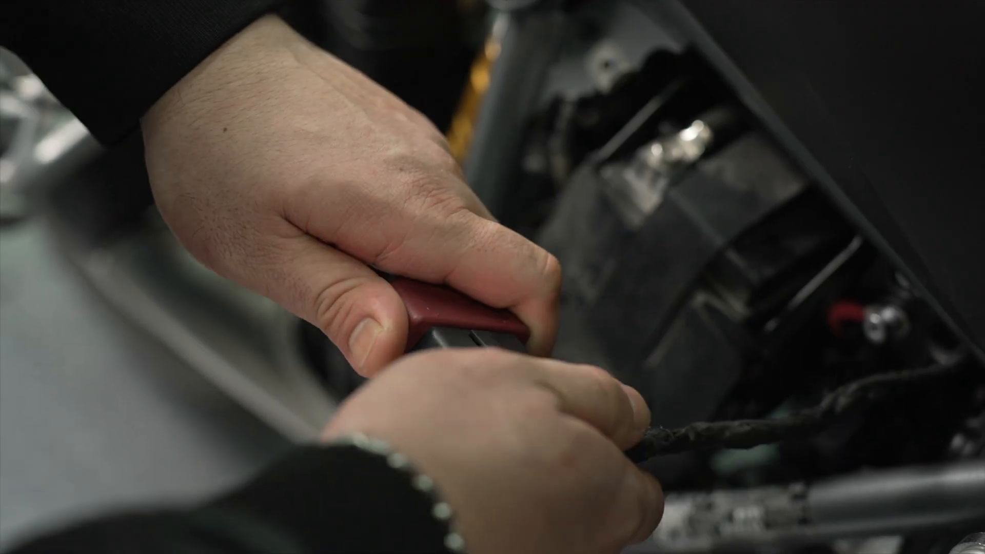
Keep the ignition in the state specified before connection. Join the selected motorcycle adapter to the M3 diagnostic connector, then seat the vehicle-side connector straight and only in its keyed orientation. Hold connector bodies rather than pulling on wires.
Route the M3 so its weight does not hang from the motorcycle harness. Keep the screen visible and the cable away from hot parts, steering movement and sharp edges. If an adapter includes auxiliary power leads, connect them only according to that exact adapter and vehicle instruction, with polarity confirmed before contact.
Completion check: Both connectors are fully seated without force, no pin is displaced, and the scanner and lead remain supported through the test.
Step 5: Set the interface language and units
At the M3 main menu, select Setting, then use Language to choose an installed language. Select Unit and choose the unit system that matches the service information you will use. The settings menu also provides a voice switch.
Installed choices can change with software revision, so use the menu on your device rather than a fixed language-count claim. Record the chosen units; a temperature or pressure value is easy to misread when the scanner and manual use different systems.
Common mistake: Changing units after recording the first data set and then comparing numbers without noting the change.
Step 6: Select the exact vehicle path
Choose Diagnose, then select the supported brand and exact model path shown for the motorcycle. Confirm any requested year, engine, market or system information against the VIN label and service data. Do not choose a neighboring model just to make communication begin.
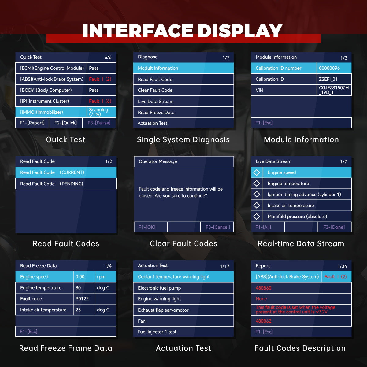
The M3 then offers Quick Test and Control Unit when supported. Use Quick Test first for a whole-vehicle baseline; use Control Unit later to investigate one system in context.
Stop: If the exact vehicle path is absent, update the exact M3 software if appropriate or confirm coverage with current support. Do not proceed under a different model.
Step 7: Run Quick Test without clearing anything
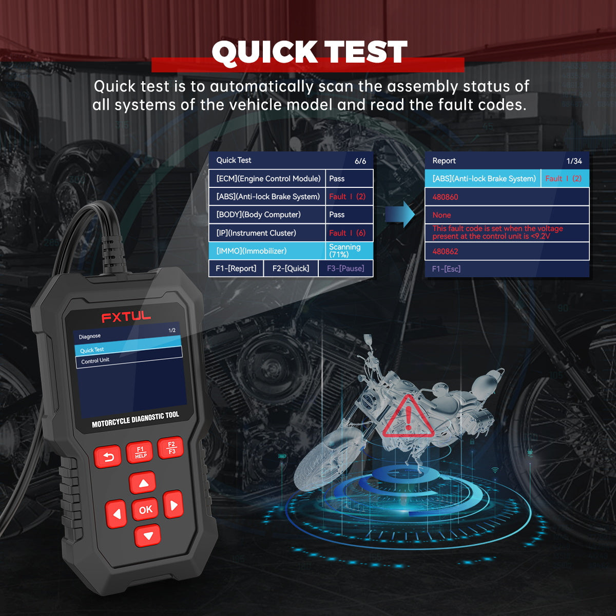
Select Quick Test. Allow the automatic scan to finish while keeping the required key/engine state and stable voltage. The screen lists detected systems and marks whether a system passes or reports faults. A long press on F3 pauses scanning if the device presents that option, but pausing is not a substitute for correcting a voltage or communication problem.
Do not press the F2 one-click clear function during this first pass. A communication failure and a module with no stored DTC are different results; record them separately.
Completion check: The scan reaches its end, and you have recorded every detected module, fault count and communication exception before changing vehicle state.
Step 8: Open the report and save the pre-clear evidence
Press F1 Report from the completed Quick Test. Review the installed-system status, each DTC and the available description. Record the complete alphanumeric code, the control unit that reported it and whether other modules hold related voltage or communication faults.
Photographing the screen is acceptable when no export is available, but make the code and module readable and associate the image with the motorcycle and test time. A description is a starting clue; it does not prove that the named component has failed.
Critical check: The original report must exist outside the scanner before any code-clear command is considered.
Step 9: Enter the affected control unit
Return to the diagnosis-mode screen, choose Control Unit, and select the module that matches the complaint and scan evidence. Start with Module Information. Record identifiers such as calibration ID, VIN where reported, serial number or production information; unexpected identity can reveal a selection error, replacement module or software mismatch.
Use the module menu to see which functions this motorcycle actually exposes. The M3 may list Read Fault Code, Clear Fault Code, Live Data Stream, Read Freeze Data, Actuation Test and Service/Maintenance, but the selected vehicle and module determine availability.
Completion check: The selected control unit identity is plausible for this motorcycle and agrees with the Quick Test record.
Step 10: Separate current, pending and historical context
Open Read Fault Code. Where the vehicle provides a choice, review CURRENT and PENDING separately. Use the arrow keys to move through every code and press the available help or freeze-frame function when shown.
For each code, record status, module, full description and any associated warning light or symptom. Current, pending and stored histories should not be treated as identical. A low-voltage or lost-communication code across several modules may describe one shared event rather than several failed modules.
Completion check: Every code has a status and module, and related system-wide patterns have been noted before parts are considered.
Step 11: Read freeze frame before live data
Select Read Freeze Data for a supported DTC. Record the values and the operating condition they represent, including engine speed, temperature, load-related values and battery voltage when available. Freeze frame is a snapshot from the fault event; live data is what the motorcycle reports now.
Compare freeze-frame units with the chosen M3 units and the service-information range. An implausible value can point to a circuit, sensor reference, ground or communication issue, but one snapshot alone does not identify the failed part.
Common mistake: Clearing the DTC first and discovering that the event snapshot has also been erased.
Step 12: Select a small live-data set and reproduce conditions safely
Open Live Data Stream. Select only the parameters needed to test the working theory, then choose Done. A small set updates more clearly and is easier to compare than selecting everything. Where supported, use the oscillogram to see change over time.
Begin with key on/engine off observations if the vehicle procedure permits. Run the engine or reproduce a load condition only when the motorcycle is secured, ventilated and the service procedure makes that test safe. Compare related values—for example a command and its feedback—rather than judging one number in isolation.
Completion check: The data either supports the suspected circuit/condition or redirects the diagnosis; it is not being used merely to decorate a report.
Step 13: Keep actuation and maintenance functions under the vehicle procedure
An Actuation Test can command items such as a warning lamp, fuel pump, fan, exhaust actuator or injector when that motorcycle supports the command. Service/Maintenance can expose procedures such as idle regulation or throttle-position learning. Both can change component state and may require temperature, fuel, transmission, stand, kill-switch or post-procedure conditions not shown in a generic menu.
Use one only when the exact service procedure names the test, the work area is controlled and you understand the expected response and stop condition. Keep people and tools away from anything that may move, heat, spray or start. Do not run an actuator repeatedly to “see what happens.”
Stop: If the required prerequisites, expected response or abort method are unknown, leave the function and obtain exact service information.
Step 14: Repair the cause, then clear and verify
Complete the mechanical or electrical repair through the motorcycle procedure. Recheck connectors, grounds, fuses, harness routing, battery condition and disturbed components before clearing. Preserve the pre-repair report, freeze frame and relevant live data.
To clear one module, select Clear Fault Code, read the warning and press F1 only when erasing the DTC and freeze information is intentional. To use Quick Test one-click clear, confirm that clearing every reported supported system is part of the repair plan. Switch ignition as prompted; do not disconnect the scanner during the operation.
Run Quick Test again under the specified key state. Verify communication, warning-light behavior and the repaired system. Where the service procedure requires an operating check or drive cycle, complete it safely and rescan. A code that does not return immediately may still require the prescribed monitor or symptom conditions.
Pass condition: The repair addresses the cause, the required systems communicate, verification conditions are complete and the before/after records remain traceable.
Use Voltage Detection as a connection check
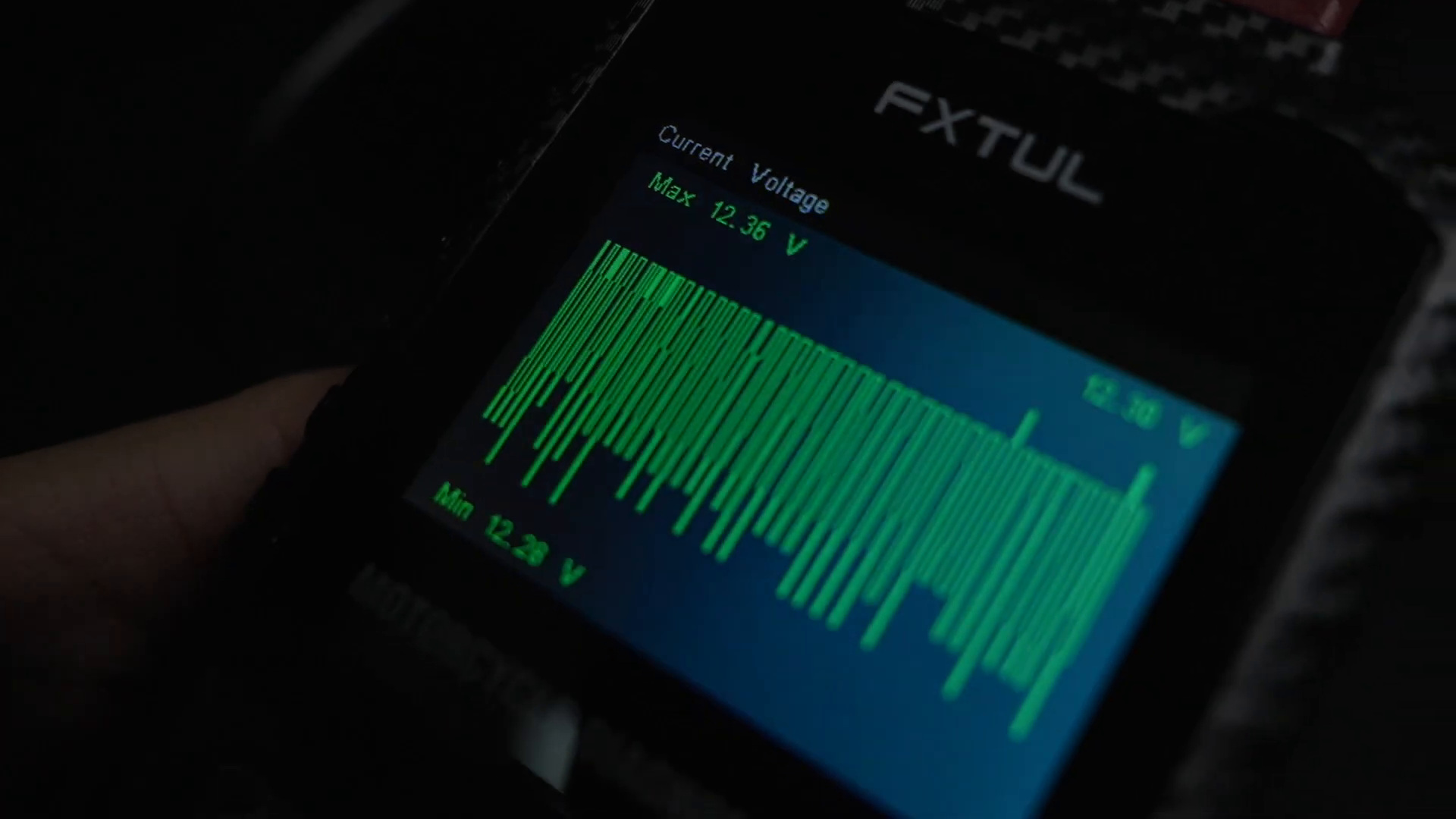
From the main menu, open Voltage Detection. The M3 shows current voltage at its diagnostic connection; press F1 WAVE for the waveform view with current, maximum and minimum values. This can reveal a connection that changes while the tool is operating.
Treat the display as diagnostic-connector voltage, not as a complete battery capacity, cranking or charging-system test. Interpret the value through the motorcycle procedure and a suitable meter or battery/charging test when required.
Stop: If voltage falls outside the vehicle procedure, fluctuates unexpectedly or communication repeatedly drops, stop scanning and correct the electrical condition before clearing codes or updating software.
Update the M3 software from a computer
Obtain an update package that is explicitly for the M3 through the current FXTUL route. Record the installed versions from Help and keep a local copy of the existing DIAGNOSE folder before replacement when the computer allows it.
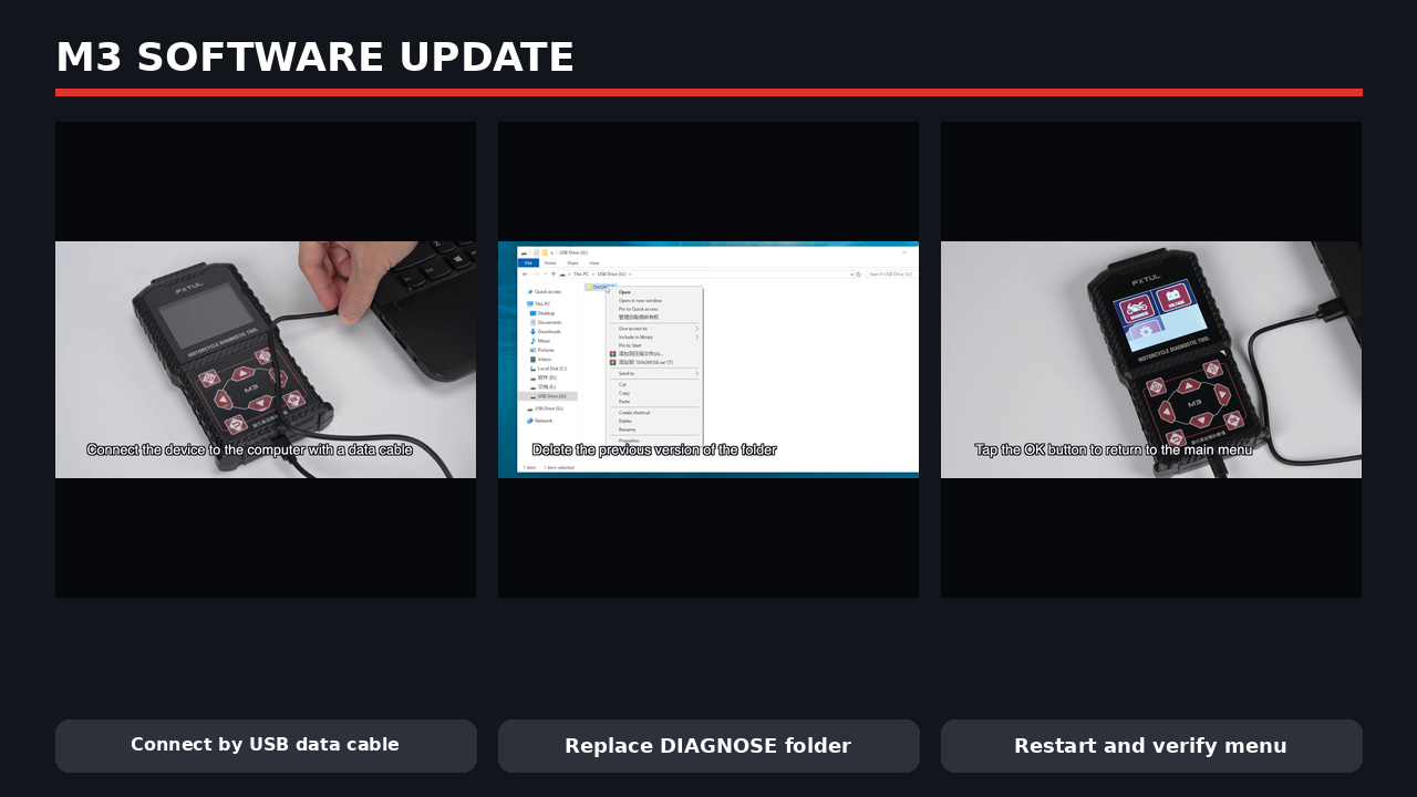
- Use a working USB data cable—not a charge-only cable—to connect the M3 to the computer.
- Wait until the computer recognizes the M3 as a removable drive. If it does not, change the data cable or computer port before touching any files.
- Unzip the exact M3 data package on the computer. Do not paste the compressed archive or rename the replacement folder.
- Open the extracted package and copy the replacement
DIAGNOSEfolder. - Open the M3 drive and verify that it is the scanner, not another removable device.
- After preserving any needed logs or backup, remove the previous
DIAGNOSEfolder as shown by the update procedure. - Paste the replacement
DIAGNOSEfolder into the root of the M3 drive and wait for file transfer to finish completely. - Eject the drive through the computer, disconnect the cable, then power the M3 again and confirm its menu and versions.
Critical check: The M3 USB interface is a 5 V computer/update connection. Do not connect a fast charger or any charger above 5 V, and do not interrupt the copy or remove the cable while files are moving.
Export a diagnostic log for support
Create a log when the M3 communicates incorrectly, omits a supported function or produces a repeatable diagnostic problem that support needs to analyze.
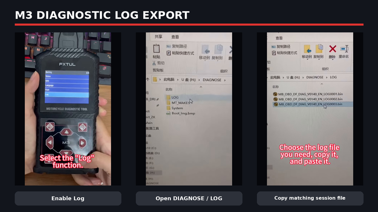
- Open Setting, select Log, and enable the logging function shown by the installed software.
- Return to the main screen and reproduce only the diagnostic sequence that causes the issue. Note the time, vehicle path and last successful screen.
- Return safely to the main screen, then connect the M3 to the computer with the USB data cable.
- Open the recognized M3 drive, then open
DIAGNOSEandLOG. - Match the file to the recorded session time and problem. Copy the required log to the computer; do not edit the original file.
- Send the copied log with the M3 versions, motorcycle identity, selected vehicle path, screenshots and a short reproduction sequence through the current support channel.
Completion check: The copied file matches the reproduced session, remains readable on the computer and is accompanied by enough context to repeat the problem.
Troubleshoot without erasing useful evidence
| Symptom | Safe next check | Avoid |
|---|---|---|
| M3 does not power from the motorcycle | Stop; verify exact adapter, connector seating, vehicle fuse/power/ground and required key state from service information | Do not apply power to uncertain pins |
| M3 powers but will not communicate | Confirm exact model path, stable voltage, connector terminals, ignition/kill-switch state and current software coverage | Do not select a similar motorcycle until one responds |
| One module does not appear | Compare Quick Test with the vehicle equipment list and module power/network diagnosis | Do not declare the module failed from one missing menu item |
| DTC returns immediately after clear | Preserve the code and freeze frame, then diagnose the circuit or condition | Do not repeat clear commands |
| Live data looks implausible | Confirm units, selected parameter, reference/ground condition and a known-good comparison | Do not replace a sensor from one value |
| Update drive does not appear | Use a known data cable and another computer USB port; confirm M3 identity | Do not use a high-voltage fast charger |
| M3 fails after an interrupted update | Stop file experiments, preserve the drive contents and contact current FXTUL support with versions and the exact package used | Do not mix M3, M4, M6 or M7 folders |
What a complete M3 diagnostic job looks like
A complete M3 job begins with the exact scanner edition, adapter, motorcycle coverage, connector condition and stable electrical setup. It preserves a full pre-clear Quick Test, ties each code to a module and status, uses freeze frame before live data, and keeps active or maintenance functions inside the vehicle procedure. It ends with a cause-based repair, an intentional clear, the required operating verification, a second scan and traceable before/after records.
That order is the difference between using a motorcycle code reader to erase a warning and using a motorcycle diagnostic tool to make a defensible repair decision.



Comments 0
Questions, fixes, and real-world diagnostic notes from readers.
Be the first to share a diagnostic result or ask a follow-up question.