
How to Use the AUTOOL LM100 Digital Vacuum Gauge

Use the AUTOOL LM100 after the refrigerant has been recovered through an approved process. Inspect and connect the gauge to a clean, rated evacuation path, install four AAA batteries, select the pressure and temperature units, program the vehicle’s vacuum target and maximum acceptable pressure, then start Evacuation mode. When the required vacuum is reached, isolate the pump correctly and use the timed retention screen to record pressure rise with temperature context.
The LM100 measures pressure during evacuation and a controlled hold. It helps you see whether pressure is falling, how long evacuation has run, and how much pressure changes after isolation. It does not recover refrigerant, identify refrigerant, remove moisture by itself, locate a leak, or prove a system is dry from one low number.
Updated August 27, 2026.
In this guide
What the LM100 measures
The AUTOOL LM100 is a standalone digital vacuum gauge for automotive A/C, HVAC and refrigeration evacuation work. It offers Evacuation and Pressure Leak Test screens, hPa, mbar, Torr and inHg pressure units, Celsius, Fahrenheit and Kelvin temperature units, a foldable hook, one brass hose connection and an optional communication link to the AUTOOL LM130.
The exact manual documents a 0–2000 mbar display range and uses both relative-vacuum and absolute-pressure wording. The current product page also publishes higher pressure-safety figures. Those are not a generic pressure-test instruction. Keep this workflow centered on procedure-controlled evacuation and retention measurement, and confirm the rating of the exact gauge, hose, valve and adapter before exposing any component to pressure.
Before you start
Open the AUTOOL manual download center and match the LM100 manual to your hardware. Obtain the vehicle procedure that states refrigerant recovery, connection layout, evacuation target, stabilization period, isolation method, hold time, allowable pressure rise and charging preparation.
Prepare a compliant recovery machine, vacuum pump, clean rated vacuum hose, core-removal or isolation tools if specified, any required charging equipment, four fresh AAA batteries, eye and hand protection and a job sheet. Position the gauge so pump oil, liquid refrigerant and charging flow cannot enter its sensor.
Stop: Do not vent refrigerant through the LM100. Do not begin evacuation on a charged system. Do not connect a contaminated hose, use the gauge in an explosive environment, exceed the lowest component rating or interpret a short hold as permission to charge an unresolved system.
Understand the LM100 controls
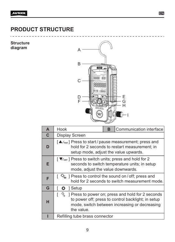
The LM100 has one brass pressure connection at the bottom and a separate communication interface near the top. The hook supports a stable upright position. Its controls are:
- Start/Pause: press to start or pause; hold two seconds to restart the measurement.
- Unit/Down: press to change pressure units; hold two seconds to change temperature units; decrease a value in Setup.
- Sound/Mode: press to toggle sound; hold two seconds to switch Evacuation and Pressure Leak Test modes.
- Setup: opens the target-value settings.
- Power/Direction: press to power on or toggle the backlight; hold two seconds to power off; changes adjustment direction in Setup.
- Up/OK behavior: raises a setup value and supports screen-specific confirmation shown by the delivered display.
Read the icon on the exact instrument before pressing. The manual notes that units cannot be changed once a measurement has started.
LM100 step-by-step operating procedure
Step 1: Define the evacuation acceptance test
Write down the vehicle, identified refrigerant, system repair state, vacuum target, target unit, required evacuation time, isolation point, stabilization period, hold duration and maximum allowed pressure rise. Use the values from the vehicle or equipment procedure, not a generic online number.
Separate three questions: whether the pump can reduce pressure, whether isolated pressure remains within the allowed window, and whether the system is ready for charging. Each requires its own criterion.
Completion check: You can state the target, hold rule and finish decision in one selected pressure unit before connecting the gauge.
Step 2: Inspect the gauge and vacuum path
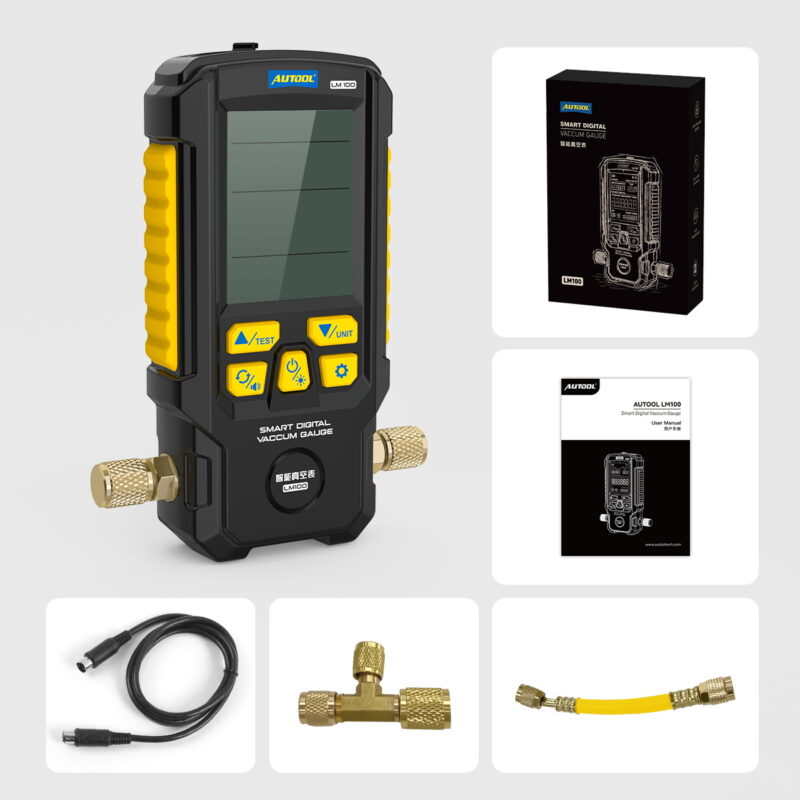
Check the LM100 housing, screen, hook, battery cover, brass connector, communication port and buttons. Inspect the vacuum hose, gaskets, valve cores, isolation valves and fittings for damage, oil, dirt and loose connections. Confirm every component is rated for the system state it may see.
Keep the gauge connection dry and clean. If oil or liquid refrigerant reaches the sensor, readings may become unreliable and service may be required. Do not clean the interior with solvent or compressed air.
Stop: Replace damaged hoses or seals and do not use a cracked, contaminated or unreadable gauge.
Completion check: The complete path is clean, intact, compatible and capable of isolating the pump without opening the system to atmosphere.
Step 3: Install four AAA batteries
Open the rear battery compartment behind the hook. Install four 1.5 V AAA batteries with the indicated polarity and close the cover fully. Use a matched set rather than mixing old and new cells.
Press Power. Verify the startup interface, battery icon, screen segments and buttons. The manual links flickering, unclear display and unexpected shutdown to depleted batteries.
Completion check: The screen is complete, stable and readable for the full planned hold.
Step 4: Build the evacuation path before opening it
Connect the LM100 at the measurement point specified by the service procedure, ideally where it can read system pressure rather than only pump pressure. Use a clean short rated hose and an isolation arrangement that lets you close off the vacuum pump while leaving the gauge connected to the system.
Keep the connection path as short and unrestricted as the approved setup permits. Long small-diameter hoses, service-port cores and extra adapters slow evacuation and create more possible leak points.
Completion check: The gauge will remain on the system side of the isolation valve during the hold, and closing that valve will not trap it only with the pump.
Step 5: Hang the LM100 and route the hose safely
Hang the instrument upright where the screen can be read without touching the hose. Keep it away from belts, fans, hot exhaust components, sharp edges and electrical terminals. Allow space for the vacuum hose to bend naturally without pulling on the brass fitting.
If an electric fan or compressor can start automatically, route and secure the setup with power isolated as the service procedure requires.
Completion check: The LM100, hose and operator remain clear of every foreseeable moving, hot and electrical hazard.
Step 6: Select mode and units before measurement
Hold the Mode key for two seconds until Evacuation is shown. Press Unit to choose hPa, mbar, Torr or inHg, and hold it for two seconds to choose °C, °F or K. Use the same units as the service procedure and job sheet.
Do not begin and then convert the target mentally. Pressure values near deep vacuum are easy to misread when switching between absolute and gauge-style scales.
Completion check: Evacuation mode, pressure unit and temperature unit match the written test.
Step 7: Program the target and alarm boundary
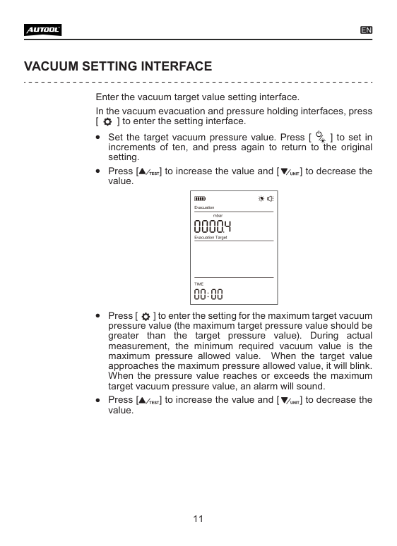
Press Setup to open the target screen. Enter the desired low absolute-pressure target from the service procedure. Advance to the maximum target field and enter the higher pressure boundary that should trigger a warning during measurement or retention. Use the direction control and up/down keys shown by the exact screen.
In an absolute-pressure scale, deeper vacuum means a lower number. The desired target should therefore be lower than the maximum acceptable boundary. If your selected unit or display behaves differently, stop and verify the manual and service values rather than reversing them by guesswork.
Completion check: Both values are documented, expressed in one unit and ordered correctly for the screen’s pressure direction.
Step 8: Start the vacuum pump and check for gross problems
Open only the evacuation path required by the service procedure and start the vacuum pump. Watch the LM100 respond. A value that does not move can indicate a closed valve, blocked core, incorrect connection, severe leak, failed pump or gauge problem.
Check every external joint using the approved vacuum-side leak method. Do not repeatedly tighten brass fittings under load and do not add refrigerant as a tracing shortcut.
Completion check: Pressure falls consistently and the gauge responds to controlled isolation or valve changes.
Step 9: Start evacuation measurement
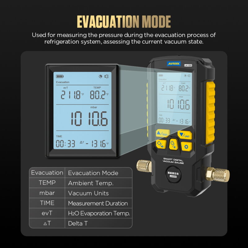
Press Start/Pause to begin the LM100 timer. The Evacuation screen shows current pressure, time, ambient temperature, water evaporation temperature and a temperature-difference field. Let the pump run for the duration and process required by the vehicle procedure.
Use the trend, not only the endpoint. A rapid initial fall followed by a slow plateau can reflect moisture boiling, restriction, oil condition, pump capacity, system volume or leakage. Ambient and component temperatures affect how quickly moisture can leave.
Completion check: The target is reached under a stable, documented setup and the specified minimum evacuation process has also been completed.
Step 10: Pause or restart without losing the test definition
Press Start/Pause again to stop the current timed measurement when the procedure calls for a controlled checkpoint. Hold the key for two seconds to restart the measurement screen. Record why you paused or restarted; otherwise the displayed time cannot be tied to the job.
If the backlight turns off after about 15 minutes, a short Power press should restore it without redefining the test. The unit automatically powers off after about 20 minutes of inactivity, so do not leave a required long hold unattended or depend on the screen as the only record.
Completion check: Every timer reset or pause is logged and does not hide a pressure-rise interval.
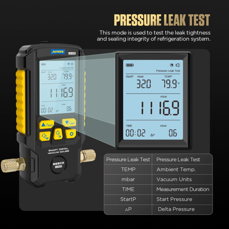
Step 11: Isolate and run the retention observation
Close the system-side isolation valve in the exact order required to protect the pump and prevent oil migration. Confirm the LM100 remains connected to the evacuated system. Hold Mode for two seconds to open Pressure Leak Test, confirm the units, then press Start to capture starting pressure, current pressure, elapsed time and pressure difference.
Do not open the system to atmosphere between evacuation and the hold. Let pressure and temperature stabilize for the specified period, then continue for the required duration.
Completion check: The pump is isolated, the gauge is still reading the system, and the complete hold begins from a documented stable start pressure.
Step 12: Interpret pressure rise without overclaiming
Compare the final pressure and difference with the vehicle acceptance rule. A fast continuous rise commonly points to a substantial leak or open path. A slower rise that levels off can involve moisture or outgassing. Temperature change, hose permeation, valve movement and a leaking test connection can imitate a system fault.
If the result fails, isolate sections and test connections using the approved diagnostic sequence. Repair the cause, replace contaminated pump oil when required and repeat the full evacuation and hold. Do not charge the system merely because the pressure rise slowed.
Completion check: The result passes the exact pressure, time and temperature-context rule or the job remains open for diagnosis.
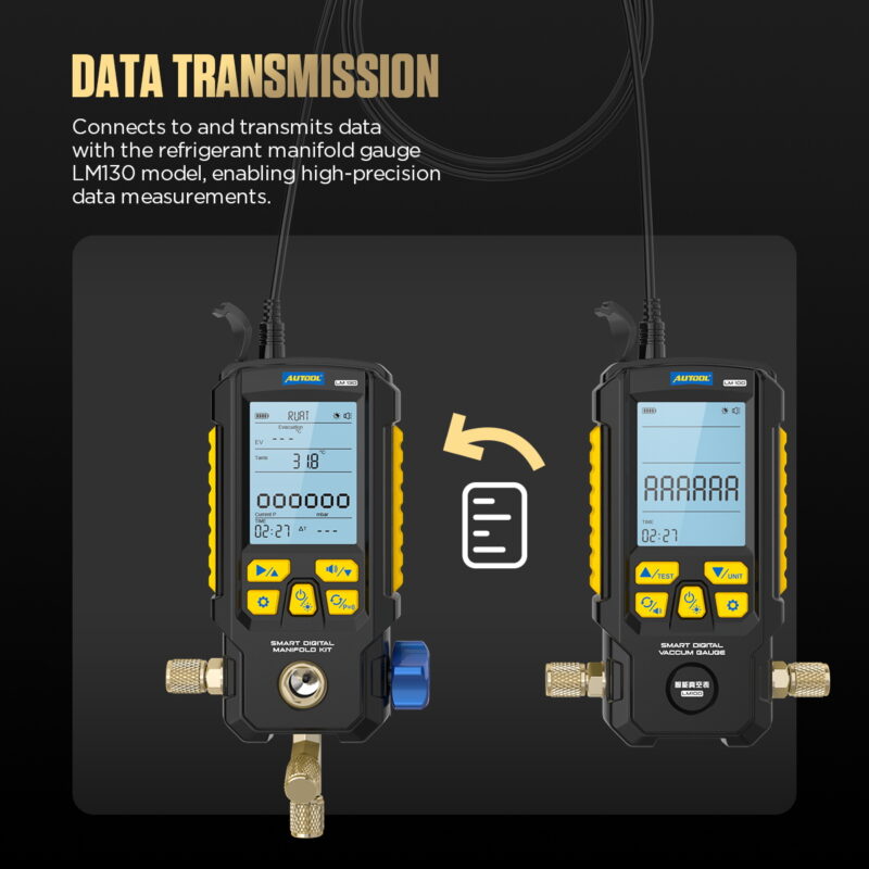
Step 13: Use LM130 communication only when needed
With both devices in a safe unpressurized setup, connect the specified communication cable between LM100 and a compatible AUTOOL LM130. Select Evacuation mode and start the measurement from the receiving manifold as documented. Confirm the remote pressure and timer respond to the LM100.
The cable transports measurement data; it does not change hose routing, sensor limits or evacuation acceptance. If the remote value disagrees, use the directly connected LM100 as the immediate reference and check the cable and receiving mode.
Completion check: Model compatibility, cable seating, mode and remote response are verified before relying on the LM130 display.
Step 14: Finish, isolate, and store the gauge
After the hold passes, follow the vehicle procedure to keep the system isolated while preparing the next service step. Close valves before removing the LM100. Manage trapped gas or refrigerant through approved equipment; never crack the gauge fitting to vent it.
Power off the LM100. Wipe the housing with a damp cloth and mild cleaner, keep solvent and oil out of the connector, cap clean fittings and store the dry gauge in a ventilated place. Remove the batteries for extended storage. The manual recommends checking the instrument for leakage and calibration about once a year.
Completion check: The system remains controlled, no material was intentionally vented, and the clean dry gauge is stored with the result attached to the correct job.
How to judge reliable LM100 results
| Gate | Pass condition | Repeat or stop when |
|---|---|---|
| Connection | Gauge reads the system side of the isolation point through a clean rated path | Gauge is trapped with the pump, connector is oily or path identity is uncertain |
| Target | Absolute-pressure direction, unit, target and maximum boundary match service data | A generic target is copied or units are converted mid-test |
| Hold | Pump is isolated, start pressure is stable, time and temperature are recorded | System is opened, timer reset is undocumented or temperature shifts sharply |
| Decision | Final pressure and rise pass the vehicle rule | A low instantaneous number is treated as proof of dryness |
Common LM100 problems
Pressure stops falling early
Check pump oil and capacity, isolation valves, service-port restrictions, hose size, connector seals and the possibility of moisture or leakage. Confirm the gauge is reading system pressure rather than a closed pocket near the pump.
Pressure rises immediately after isolation
Verify the isolation order and check every test connection first. A large rise can indicate a major leak or open valve, but the test rig itself must be ruled out before condemning the vehicle.
Target alarm appears at the wrong time
Recheck the selected unit and confirm that the desired target is the lower absolute pressure while the maximum boundary is higher. Re-enter values from the written procedure instead of reversing them until the alarm disappears.
The screen is dim or shuts down
Replace all four AAA batteries as a matched set. Remember the documented 15-minute backlight timeout and 20-minute inactivity shutdown; log long holds independently.
AUTOOL LM100 FAQ
Is the LM100 a complete A/C manifold gauge?
No. It is a single-connection digital vacuum and retention gauge. It does not provide separate high- and low-side manifold valves or a refrigerant database.
Does a low LM100 reading prove the system is dry?
No. The system must reach the specified absolute-pressure target through the required process and then pass the specified isolated decay test. Moisture, leaks, setup problems and temperature all affect the result.
Can I connect the LM100 to a charged A/C system?
Only if a current exact-model procedure and every component rating explicitly permit that state. This tutorial uses the LM100 after compliant recovery in an evacuation path and does not authorize generic positive-pressure connection.
What batteries does the LM100 use?
It uses four 1.5 V AAA batteries.
Can the LM100 send data to another gauge?
The manual documents a cable connection to a compatible AUTOOL LM130 for vacuum data display and timing. Confirm the receiving model, mode and cable before use.
The reliable LM100 workflow
Recover refrigerant correctly, define the vehicle’s vacuum and decay criteria, inspect and protect the measurement path, install four AAA batteries, select units, set a lower target and higher alarm boundary, evacuate while watching time and temperature, isolate the pump without disconnecting the gauge, record pressure rise for the specified hold, investigate any failure, then isolate and store the LM100 clean and dry. That turns a vacuum reading into a reproducible service decision.



Comments 0
Questions, fixes, and real-world diagnostic notes from readers.
Be the first to share a diagnostic result or ask a follow-up question.